High Availability and Redundancy
The High Availability (HA) feature ensures that the services remain available for both bridged and routed traffic during switch or DPU failure or outage. High Availability is achieved by enabling redundant paths for traffic flows and synchronizing the flow state across these paths, which is critical for stateful services.
HA peers
HA peering requires identical hardware platforms running the same software version. HA peering between two different hardware platforms is not supported, for example, if one Smart Switch is N9324C-SE1U and the other Smart Switch is N9348Y2C6D-SE1U.
The HA infrastructure ensures that the service firewall state is synchronized between configured peers. If the firewall service is not ready or becomes unavailable on a switch, HA disables the network paths through that switch and directs traffic to the other available peer. When two switches are configured for HA (Active/Active HA model), the service firewall state is synchronized between the two peering switches. Currently, only two smart switches can be configured as HA peers.
 Note |
Due to VXLAN headers and the MAC-IP-UDP encapsulation for inline flow sync of traffic between HA peers, a host should not send jumbo frames larger than 9216 - 10B (for HA) - 30B (for macsec) = 9174 B of 9134B in case of VXLAN + MACsec. Effectively, the maximum packet size that is currently supported is 9000 bytes. |
Connectivity between HA peers
HA communication requires Layer 3 connectivity with IPv4 addresses in the default VRF which you must provide between the two switches that make the HA pair. The security subsystem implements stateful inspection through flow and state synchronization.
Layer 3 connectivity between HA peers is required to carry:
-
control plane traffic between the Hypershield Agents on the HA peers, for keepalives and state information exchange
-
control plane traffic between the DPU pairs (DPU1 – DPUn) of the HA peers, for keepalives and flow state sync
-
data traffic for inflow flow-sync for flow learns, and
-
data traffic for inline flow-state sync for stateful traffic inspection.
The HA connectivity can be established using dedicated or shared links between the HA peers:
-
Dedicated Port Channel: A specific port channel set up exclusively for the HA synchronization between peers.
-
Shared Port Channel: Utilizes an existing port channel, such as a vPC peer link, already connecting the peers.
Note |
The links should be at least 25G and directly connected, but in most deployments the minimum bandwidth may be 2 x 400G unless traffic flows between the Smart Switches are symmetric. The port channel provides link redundancy. SVIs over Layer 2 port channels can also be used to establish this connectivity. |
Guidelines and limitations
-
HA connectivity over routed or VXLAN fabrics is not supported in 10.6(3s)F.
-
NTP or PTP must be configured and be in sync between the two HA switches so that the time and flows are synchronized on both the switches
-
For HA to work correctly, the DPU load-balancing configuration must be identical on both Smart Switches in the same HA pair, and the service VRF and service VLAN configuration must be identical on both devices.
-
Even if HA is configured, temporary traffic interruptions might occur for asymmetric flows if there is a mismatch in policy versions, or flow-sync is incomplete or in-progress. You may also experience temporary traffic interruptions when traffic deflections occur in the network.
-
Interruptions can be observed while establishing or recovering HA connectivity between switches with active firewall services.
Loss of connectivity between HA peers
If HA peers lose connectivity (a split-brain scenario), both switches disable the traffic deflection mechanism and operate as standalone firewall services. This state can result in two types of traffic issues:
-
Dropped Traffic: Traffic arriving at a HA peer that is not ready can be dropped.
-
Asymmetric Flow Failures: Independent inspection by both peers may lead to asymmetric flow failures.
Service Traffic Deflection
When high availability is configured, if the firewall service subsystem is not ready to process traffic despite the networking infrastructure being fully operational, traffic is deflected to the HA peer that is ready, to minimize traffic loss. This deflection is also necessary during system initialization, and when the firewall is not in service. NX-OS manages this deflection for both routed and bridged traffic that is configured for traffic inspection.
Additionally, when the configured HA peers are detected as having mismatched software versions, incompatible platforms, differences
in DPU load-balance mechanisms, or if the DPU pairs are unable to establish steady connectivity to each other, one of the
HA peers having a fully functional firewall service takes-over all traffic as a firewall service that is ready and the other peer yields and transitions to a firewall service that is not-ready. Traffic is then deflected in a similar manner towards the ready firewall service.
Routed Traffic Deflection
Deflection of routed traffic to the HA peer is handled in the following ways:
-
VRF contexts configured for routed-traffic inspection are isolated when the local service firewall is not ready.
-
This allows for routing protocols such as BGP, OSPF to withdraw routes or advertise routes with higher metrics than the HA peer, to the upstream devices.
-
Traffic arriving from the Layer 3 fabric is thereby deflected towards the HA peer.
-
On HA peers configured with HSRP, the HSRP groups in the isolated VRF transition gracefully to
INIT, when the local service firewall is not ready. This allows the other peer to entirely take over the traffic for the HSRP gateway.
-
-
On HA peers that are part of a vPC domain, the vPCs handling traffic for any VLANs, whose SVIs pertain to VRFs configured for service firewall are suspended, if the local service firewall is not ready, while the peer is ready.
-
This vPC suspension mechanism is conducted independent of the vPC role and is entirely based on the service firewall readiness.
-
vPC peers support active-active forwarding for first hop redundancy protocols such as HSRP, VRRP, and for anycast gateway in VXLAN. When a vPC is suspended, the traffic from dually homed hosts is directed only to the ready firewall service.
-
In a VXLAN fabric, type-5 routes for VRFs configured for routed-traffic inspection are always advertised with the PIP by the vPC leaf switches, regardless of the advertise-pip configuration. When VRF isolation takes effect, traffic is deflected to the ready HA peer, as only a single preferred path is available.
-
When HA state is ready/ready, the EVPN route is advertised with VIP from both peers. However, when one of the peer is put in maintenance mode (no-inservice) the peer switch advertises the routes with PIP. When the peer switch is put back to in-service mode, the routes are again advertised with VIP. These transitions from VIP to PIP or PIP to VIP can cause momentary traffic loss on the box which actively forwards traffic. PIP is only advertised when the HA state is ready/not ready.
-
In a VXLAN fabric, type-2 routes for VPC hosts in VRFs configured for routed-traffic inspection are advertised with the VIP when both HA peers are ready. These routes are withdrawn by the HA peer that is not ready and will be advertised with the PIP of the ready peer.
-
Bridged Traffic Deflection
Deflection of bridged traffic to the HA peer is handled in these ways:
-
On HA peers that are part of a VPC domain, the VPCs handling traffic for any VLANs that are configured for bridged traffic inspection, are suspended when the local service firewall is not ready, and the peer is ready.
-
In a VXLAN fabric, MAC routes and Type-3 Inclusive Multicast Ethernet Tag (IMET) routes in the VLANs configured for bridged-traffic inspection are advertised with the VIP when both HA peers are ready. These routes are withdrawn by the HA peer that is not ready and are advertised with the PIP of the ready peer.
Show commands
The output of the show service-acceleration status details command can show the VLANs in forwarding ready state when bridged traffic in those VLANs can be successfully redirected to the DPUs for inspection. When high-availability
is configured and HA peering is successfully established, bridged traffic from vPCs or VXLAN fabric can arrive at the Smart
Switch only when the firewall service state for the Smart Switch is ready.
Smart Switches deployed as vPC peers
Smart Switches can be deployed as vPC peers. Users must ensure configuration consistency for the feature service-acceleration and service firewall configuration across the two vPC peers.
Users must ensure firewall policies to permit traffic are available for all the interface IPs used by the individual vPC peers, when VPC peer-gateway is enabled and the VRFs pertaining to these interface IPs are enabled for service firewall. Traffic that is destined to interface IPs of a vPC peer, that hashes to the other peer when peer gateway feature is enabled, is inspected by the DPU on the other peer, before being sent over the peer link.
Configure vPC delay-restore timers of 300s and vPC auto-recovery reload-delay timers of 360s to ensure that the HA peers are able to detect each other during switch reloads, before the vPCs are recovered.
Traffic loss may occur if vPCs are down on the smart switch with the firewall service that is ready and vPCs are suspended on the non-ready HA peer.
If the vPCs carry traffic associated with VRFs or VLANs that are not configured for firewall inspection, such traffic may be impacted or deflected when the traffic deflection mechanisms take effect.
If HA is configured on vPC peers, traffic deflection for hosts that are singly homed or connected through orphan ports to only one vPC peer is not supported. When the firewall is not in-service, traffic from orphan hosts can drop. In other failover scenarios of peer incompatibility, where the firewall is in-service on both peers, traffic from orphan hosts can be independently inspected, without flow-sync taking effect.
Traffic deflection topologies
This section discusses three scenarios of Smart Switches with high-availability configured:
-
Smart Switches as transit routers
-
Smart Switches as Active/Standby HSRP GW
-
Smart Switches as vPC peers
Smart Switches as transit routers
The diagram illustrates a High Availability (HA) topology where two peer devices (Peer 1 and Peer 2) act as transit routers between customer networks (Network A and Network B) and the broader infrastructure. The devices are connected through a Layer 3 Port Channel (L3 PO), which serves as the HA peer link for state synchronization and control signaling.
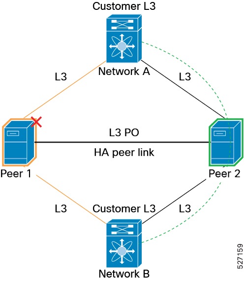
In this topology, VRF isolation influences route advertisements and deflects traffic towards Peer 2.
This topology uses VRF-aware routing to ensure that traffic is always directed to the healthy node. By isolating the routing tables, the network can perform graceful traffic redirection, ensuring that even if one transit router (Peer 1) goes offline, the other (Peer 2) seamlessly assumes the routing responsibility without disrupting the customer networks.
Smart Switches as Active/Standby HSRP GW
This diagram illustrates a High Availability (HA) Gateway deployment, typically used in enterprise networks to ensure continuous connectivity for hosts. The setup consists of two peers, Peer 1 and Peer 2, connected through a Layer 3 Port Channel (L3 PO), which acts as the HA peer link.
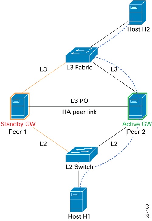
In this topology, HSRP moves to INIT on Peer 1 and all traffic is deflected to Peer 2. VRF isolation deflects the traffic from Layer 3 fabric to Peer 2.
This architecture ensures that even if one peer becomes unavailable, the network intelligence—driven by HSRP and VRF isolation—seamlessly reroutes traffic to the active peer, maintaining uninterrupted communication for the connected hosts.
Smart Switches as vPC peers
This diagram illustrates a network maintenance or failure scenario in a Virtual Port Channel (vPC) environment. The setup features two peers, Peer 1 and Peer 2, connected to a common Layer 3 Fabric and various hosts (H3, VH1, VH2, H4), all operating within VLAN 100.
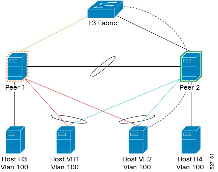
In this topology, vPCs on Peer 1 are suspended to deflect traffic from hosts to Peer 2 and VRF isolation deflects the traffic from Layer 3 fabric to Peer 2.
The combination of suspending vPCs on the inactive peer and leveraging VRF isolation to redirect traffic from the L3 fabric ensures that all communication—both from the hosts and from the core network—is seamlessly shifted to Peer 2. This allows for the graceful isolation of Peer 1 without disrupting the connectivity of the hosts in VLAN 100.
Configure connectivity for High Availability
Use this procedure to configure the High Availability (HA) connectivity, establish the loopback IP reachability through static routes or routing protocols over this HA connection.
Procedure
|
Step 1 |
Perform any one of these procedures based on the interface. |
||
|
Step 2 |
Create a loopback interface for the HA source-interface using the interface loopback instance command. Example: |
||
|
Step 3 |
Configure an IP address for the interface using the ip address ip-address/length command. Example:For more information about IP addresses, refer to Cisco N9000 Series NX-OS Unicast Routing Configuration Guide. ip-address/length : Sets an IP address for the loopback.
|
||
|
Step 4 |
Verify the loopback interface configuration. Example:
|
Configure High Availability connectivity over Layer 2 interfaces
Provision and configure HA connectivity over vPC peer link or Layer 2 port channel over vPC peer link if the HA peers are vPC peers and part of the same vPC domain. The vPC peer link must allow the VLAN used for HA connectivity. Otherwise, a Layer 2 port channel can be used if the HA peers are not vPC peers.
Procedure
|
Step 1 |
Create VLAN in global configuration mode using the vlan vlan-id command. Example: |
|
Step 2 |
Use the name vlan name command to assign a descriptive name to the VLAN to help identify its function as High Availability. Example: |
|
Step 3 |
Use the interface vlan vlan-id command to enter the configuration mode for the Switch Virtual Interface (SVI). Example: |
|
Step 4 |
Use the description descriptive label SVI command to add a label to the SVI to clarify its role as the High Availability link's virtual interface. Example: |
|
Step 5 |
Use the ip address ip-address/length command to assign an IP address and subnet mask to the SVI, allowing the switch to route traffic for this VLAN. This provides HA loopback reachability over SVI. Example: |
|
Step 6 |
Use the no shutdown command to enable the interface. Example: |
|
Step 7 |
Use the interface port-channel port-channel-number command to access the configuration mode for an existing Port-Channel (vPC peer-link). Example: |
|
Step 8 |
Use the switchport trunk allowed vlan add vlan-id command to add HA VLAN to the allowed VLAN. Example: |
|
Step 9 |
Use the exit command to exit the current interface configuration mode and return to the global configuration mode. Example: |
What to do next
For the next steps, refer to Configure connectivity for High Availability.
Configure High Availability connectivity over Layer 3 interfaces
Provision and configure HA connectivity over dedicated Layer 3 port channel.
Procedure
|
Step 1 |
Use the configure terminal command to enter the global configuration mode. Example: |
|
Step 2 |
Use the interface port-channel port-channel-number command to specify the port-channel interface to configure and enter the interface configuration mode. Example: |
|
Step 3 |
Use the description descriptive label command to assign a descriptive label to the interface, making it easier to identify it as a High Availability link during troubleshooting or management. Example: |
|
Step 4 |
Use the no switchport command to configure the interface as a Layer 3 (routed) port instead of a Layer 2 (switching) port, allowing it to support IP addressing and routing protocols. Example: |
|
Step 5 |
Use the ip address ip-address/length command to assign an IP address and subnet mask to the routed interface, enabling it to communicate with the peer device on the other end of the link. Example: |
|
Step 6 |
Use the exit command to exit the current interface configuration mode and return to the global configuration mode. Example: |
What to do next
For the next steps, refer to Configure connectivity for High Availability.
Configure High Availability
After setting up High Availability (HA) connectivity and establishing the loopback IP reachability, set up the high-availability configuration for the Hypershield service subsystem.
Perform these steps to establish HA connectivity and configure HA.
Procedure
|
Step 1 |
Use the service system hypershield command to enter service system mode and access the configuration mode for the Hypershield system. Example: |
||
|
Step 2 |
Use the high-availability command to enter the sub-mode specifically for high-availability settings. Example: |
||
|
Step 3 |
Set the source interface using the source-interface command to designate the interface whose IP address is used as the source address for the HA connectivity. Example:
|
||
|
Step 4 |
Use the peer command to specify the HA IP address of the peer switch. Note that the peer IP address must match the IP address of the configured HA source-interface on the peer. Example:
|
||
|
Step 5 |
Activate the configuration using the no shutdown command to enable HA. Example:
|
||
|
Step 6 |
. Use the exit command to exit the configuration mode. Example: |
Verify High Availability
Run the show commands and verify the service-acceleration and High Availability configuration.
Use the show running-config service-acceleration command to view the configuration of the service acceleration feature on the switch.
switch# show running-config service-acceleration
feature service-acceleration
service system hypershield
  source-interface loopback100
  high-availability
    source-interface loopback101
    peer 192.168.10.2
    no shutdown
  service firewall
    vrf blue module-affinity dynamic
    vrf red module-affinity dynamic
    vlan id 100 bridged-traffic module-affinity dynamic
    in-service
Use the show service-acceleration high-availability status command to view the high-availability status of the service acceleration system.
switch# show service-acceleration high-availability status
  Service System: hypershield
    HA Source Interface: loopback101 (192.0.2.2)
    HA Admin State: no-shutdown
    Agent Status for Service Firewall: ready
    Agent HA Status: ready
    Peers:
      PeerIP              Peer Service State  HA State with Peer  Reason
      ------------------- ------------------  ------------------  --------------
      192.168.10.2           ready               ha-ok               all criteria met
 Feedback