Layer 2 isolation for micro-segmentation

This chapter describes how local-proxy ARP and Layer 2 isolation support micro-segmentation and how to configure and verify the feature.

Local-proxy ARP and Layer 2 isolation

A local-proxy ARP with Layer 2 isolation is a network security mechanism that

  • directs IPv4 traffic between same-subnet endpoints through the smart switch for inspection and policy enforcement

  • prevents endpoints from bypassing the smart switch by blocking direct Layer 2 communication, and

  • prevents unnecessary traffic forwarding to the switch by responding with the gateway MAC address only when the destination is reachable.

Components of local-proxy ARP with Layer 2 isolation

Local-proxy ARP with Layer 2 isolation uses these components to move same-subnet IPv4 traffic through the smart switches:

  • Private VLAN isolation: Prevents direct Layer 2 communication between endpoints on an intermediate Layer 2 switch or distributed virtual switch.

  • Receive-only VLAN mapping: Maps the secondary VLAN to the primary VLAN on ingress without changing the VLAN on egress.

  • Enhanced local-proxy ARP: Returns the smart switch gateway MAC address when the destination is known and reachable.

  • Service VLAN Layer 2 isolation: Blocks direct Layer 2 traffic that may use learned MAC or ARP information, to prevent bypassing the DPU stateful security inspection.
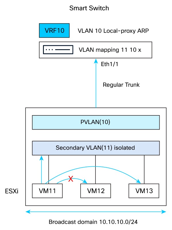
Topology for local-proxy ARP and Layer 2 isolation

The topology illustrates how local-proxy ARP and Layer 2 isolation secure communication between virtual machines in the same IPv4 subnet:

  • The ESXi private VLAN (PVLAN) configuration prevents direct Layer 2 communication between virtual machines in isolated secondary VLAN 11.

  • A regular trunk between the ESXi host and Ethernet1/1 on the smart switch carries primary VLAN 10 and secondary VLAN 11.

  • Ethernet1/1 maps traffic received in secondary VLAN 11 to primary service VLAN 10. The receive-only mapping does not translate VLAN 10 to VLAN 11.

  • The VLAN 10 switched virtual interface (SVI) provides the default gateway for the 10.10.10.0/24 subnet and uses enhanced local-proxy ARP.

  • VRF 10 redirects routed traffic to the service firewall, and the service VLAN isolation policy prevents bridged traffic from bypassing inspection.

  • The smart switch routes eligible same-subnet IPv4 traffic through the service firewall while maintaining Layer 2 isolation.

Figure 1. Local-proxy ARP topology with Layer 2 isolation
Local-proxy ARP topology with Layer 2 isolation

Key benefits

  • Maintains Layer 2 isolation for security.

  • Supports local-proxy ARP for intra-subnet communication.

  • Enforces DPU stateful filtering.

Guidelines and limitations for local-proxy ARP and Layer 2 isolation

Review these guidelines and limitations before configuring same-subnet IPv4 traffic inspection through a service firewall.

Traffic support

  • Beginning with NX-OS Release 10.6(3s)F, local-proxy ARP with Layer 2 isolation supports IPv4 bridged traffic only. Neighbor Discovery proxy is not supported.

  • Layer 2 isolation drops bridged IPv4, IPv6, and non-IP traffic. IPv6 endpoint communication is not supported because Neighbor Discovery proxy is not supported.

  • Local-proxy ARP with Layer 2 isolation supports smart switches in a virtual port channel (vPC) topology.

Configuration requirements

  • Configure an SVI for each isolated service VLAN. Associate the SVI with a virtual routing and forwarding (VRF) instance enabled for routed-traffic inspection.

  • Configure enhanced local-proxy ARP with the reachable keyword. The smart switch responds only after it confirms destination reachability.

  • A service VLAN can use either the default redirect action or the isolate action. An isolated VLAN does not support a nondefault module affinity.

  • The system does not validate SVI, VRF, or enhanced local-proxy ARP dependencies for the isolation action. Configure and verify each dependency separately.

VLAN mapping behavior

  • To change an existing mapping between bidirectional and receive-only operation, remove the mapping and create it again with the required direction.

  • Receive-only VLAN mapping supports single-tagged packets when the inner VLAN ID is 0.

  • Spanning Tree Protocol (STP) is not supported on interfaces configured with switchport vlan mapping x y rx . STP requires symmetric bidirectional VLAN mapping.

Software downgrade considerations

  • Before downgrading to a release earlier than NX-OS Release 10.6(3s)F, remove mappings that use the rx keyword.

Configure local-proxy ARP with Layer 2 isolation

Use this task when the subnet gateway is an SVI on smart switches. This configuration maps isolated secondary VLANs to the primary VLAN, forcing same-subnet traffic through Layer 3 firewall inspection and enabling enhanced security.

Follow these steps to configure local-proxy ARP with Layer 2 isolation:

Before you begin

  • Configure a private VLAN on the intermediate Layer 2 switch or distributed virtual switch to prevent direct endpoint communication.

  • Allow the primary VLAN on a promiscuous trunk. Otherwise, allow both VLANs on a regular trunk and use receive-only VLAN mapping on the smart switch.

  • Create the translated VLAN on the smart switch and allow it on the Layer 2 trunk.

  • Configure VRF red for routed-traffic inspection.

Procedure


Step 1

Enter global configuration mode.

Example:

switch# configure terminal

Step 2

Select the Layer 2 trunk interface that connects to the intermediate switch or distributed virtual switch.

Example:

switch(config)# interface Ethernet1/1

Step 3

Enable VLAN mapping and map the secondary VLAN to the primary VLAN on ingress.

Example:

switch(config-if)# switchport mode trunk
switch(config-if)# switchport vlan mapping enable
switch(config-if)# switchport vlan mapping 11 10 rx
switch(config-if)# switchport trunk allowed vlan 10
switch(config-if)# no shutdown

For more information, refer to Configure rx-only VLAN mapping.

Step 4

Configure the SVI for the primary VLAN and enable enhanced local-proxy ARP.

Example:

switch(config)# interface Vlan10
switch(config-if)# vrf member red
switch(config-if)# ip address 10.10.10.254/24
switch(config-if)# ip local-proxy-arp reachable
switch(config-if)# no shutdown

For more information, refer to Configure proxy.

Step 5

Configure the primary VLAN as an isolated service VLAN under the service firewall.

Example:

switch(config)# service system hypershield
switch(config-svc-sys)# source-interface loopback2
switch(config-svc-sys)# service firewall
switch(config-svc-pol-fw)# vlan id 10 bridged-traffic isolate

For more information, refer to Configure VLAN layer 2 isolation.

Step 6

Configure the SVI VRF for traffic redirection to the firewall service.

Example:

switch(config-svc-pol-fw)# vrf red module-affinity dynamic

For more information, refer to Configure Service VRFs.

Step 7

Enable the service firewall.

Example:

switch(config-svc-pol-fw)# in-service

For more information, refer to Enable service firewall.


The smart switch routes eligible same-subnet IPv4 traffic through the service firewall and drops bridged traffic on isolated service VLANs.

Configure local-proxy ARP on an EVPN SVI

Use this task to enable local-proxy ARP on an Ethernet VPN (EVPN) switched virtual interface (SVI) configured with the anycast gateway. Local-proxy ARP allows the gateway to direct same-subnet traffic efficiently.

Follow these steps to enable local-proxy ARP on an EVPN SVI:

Procedure


Step 1

Enter global configuration mode.

Example:

switch# configure terminal

Step 2

Select the SVI.

Example:

switch(config)# interface Vlan10

Step 3

Enable the anycast gateway and local-proxy ARP on the SVI.

Example:

switch(config-if)# fabric forwarding mode anycast-gateway proxy

Note


The ip local-proxy-arp command is not available on an SVI that uses fabric forwarding mode anycast-gateway , with or without the proxy keyword.


Verification commands for local-proxy ARP and Layer 2 isolation

Use these commands to verify the VLAN mapping, ARP entries, Layer 2 isolation, and service-acceleration status.

Table 1. Verification commands for local-proxy ARP and Layer 2 isolation

Command

Purpose

show interface Ethernet1/1 vlan mapping

Displays VLAN mappings on the specified interface.

show ip arp static vrf vrf-name

Displays static ARP entries for the specified VRF.

show vlan filter

Displays the VLAN filter configuration.

show vlan access-list access-list-name

Displays the VLAN access-list configuration.

show service-acceleration status details

Displays detailed service-acceleration status.

show ip interface vlan vlan-id

Displays whether local-proxy ARP is enabled on the VLAN interface.