Configure VRRP

This chapter contains the following sections:

About VRRP

VRRP (Virtual Router Redundancy Protocol) is a protocol that allows a group of routers to share a virtual IP address, providing transparent failover at the first-hop IP router.

  • Configures a group of routers to share a virtual IP address.

  • Elects one router in the group to handle all packets for the virtual IP address.

  • Other routers remain in standby and take over if the active router fails.

VRRP operation

VRRP (Virtual Router Redundancy Protocol) is a protocol that allows multiple routers to form a group and share a single virtual IP address, which is used as the default gateway for LAN clients.

  • Enables a group of routers (VRRP group) to share a virtual IP address.

  • Provides redundancy for the default gateway, ensuring continuous network access if the primary router fails.

  • Allows LAN clients to be configured with a single default gateway IP address, simplifying configuration and improving reliability.

How VRRP operation provides gateway redundancy for LAN clients

LAN clients can determine their first-hop router to a remote destination using either dynamic discovery protocols or static configuration. Dynamic methods include Proxy ARP, routing protocols, and ICMP Router Discovery Protocol (IRDP). However, these methods can introduce configuration and processing overhead, and may result in slow failover if a router becomes unavailable. Static configuration of a default router simplifies client setup but creates a single point of failure, potentially isolating the client from the network if the default gateway fails. VRRP addresses this by allowing multiple routers to share a virtual IP address, which clients use as their default gateway, thus providing redundancy and seamless failover.

  • Proxy ARP: The client uses ARP to resolve the destination, and a router responds with its MAC address.

  • Routing protocol: The client listens to dynamic routing protocol updates (such as RIP) to build its routing table.

  • ICMP Router Discovery Protocol (IRDP): The client runs an ICMP router discovery client.

When using VRRP, a group of routers share a virtual IP address. The primary router (IP address owner) forwards packets sent to this address, while backup routers monitor the primary's status. If the primary fails, the backup with the highest priority takes over the virtual IP address, ensuring uninterrupted service. When the original primary recovers, it resumes its role.


Note


Packets received on a routed port destined for the VRRP virtual IP address terminate on the local router, regardless of whether it is the primary or a backup. These include ping and Telnet traffic. Packets received on a Layer 2 (VLAN) interface destined for the VRRP virtual IP address terminate on the primary router.


Figure 1. Basic VRRP Topology

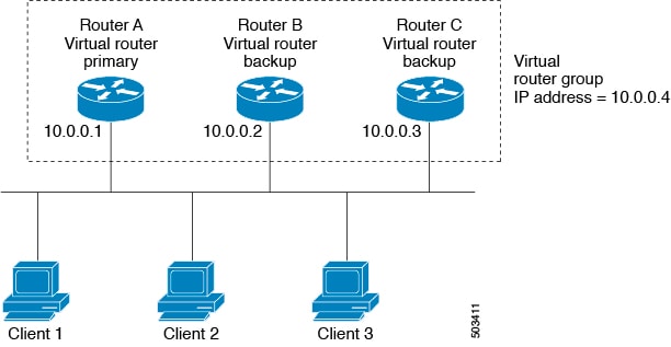
Example: VRRP in a VLAN topology

In a basic VLAN topology, Routers A, B, and C form a VRRP group. The group's IP address matches the Ethernet interface address of Router A (10.0.0.1). Clients 1 through 3 are configured with 10.0.0.1 as their default gateway. Router A acts as the primary and forwards packets sent to the virtual IP address. If Router A fails, the backup router with the highest priority becomes the new primary and takes over the virtual IP address, maintaining network connectivity for the clients. When Router A recovers, it resumes its role as primary.

VRRP benefits

  • Redundancy: Enables configuration of multiple routers as the default gateway, reducing the possibility of a single point of failure in a network.

  • Load sharing: Allows traffic to and from LAN clients to be shared by multiple routers, distributing the load more equitably.

  • Multiple VRRP groups: Supports multiple VRRP groups on a router interface, enabling redundancy and load sharing in LAN topology.

  • Multiple IP addresses: Allows management of multiple IP addresses, including secondary addresses, and supports VRRP configuration on each subnet.

  • Preemption: Enables a higher priority backup router to preempt a backup that has taken over for a failing primary.

  • Advertisement protocol: Uses a dedicated IANA standard multicast address (224.0.0.18) and protocol number 112 for VRRP advertisements, minimizing unnecessary multicasts and aiding in packet identification.

  • VRRP tracking: Ensures the best VRRP router is primary by altering priorities based on interface states.

Multiple VRRP groups

Multiple VRRP groups refer to the configuration of more than one Virtual Router Redundancy Protocol (VRRP) group on a single physical router interface.

  • Router interfaces can support multiple VRRP groups simultaneously.

  • The number of supported VRRP groups depends on router processing and memory capabilities.

  • An interface can act as a primary for one VRRP group and as a backup for one or more other groups.

Multiple VRRP groups can be configured on a single router interface, allowing for flexible redundancy and load sharing in network topologies.

  • Router processing capability affects the number of VRRP groups supported.

  • Router memory capability also impacts the number of supported groups.

In a topology with multiple VRRP groups, the interface can serve as a primary for one group and as a backup for others.

Table 1. VRRP Group Role Comparison

Group

Primary Router

Backup Router

VRRP group 1

Router A (IP 10.0.0.1)

Router B

VRRP group 2

Router B (IP 10.0.0.2)

Router A


Note


For the number of supported VRRP groups, see the Cisco Nexus 9000 Series NX-OS Verified Scalability Guide .


The following image shows a LAN topology in which VRRP is configured so that Routers A and B share the traffic to and from clients 1 through 4. Routers A and B act as backups to each other if either router fails.

Figure 2. Load Sharing and Redundancy VRRP Topology

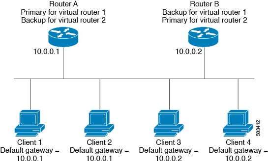
Example: Overlapping VRRP groups in a LAN topology

This topology contains two virtual IP addresses for two VRRP groups that overlap. For VRRP group 1, Router A is the owner of IP address 10.0.0.1 and is the primary. Router B is the backup to Router A. Clients 1 and 2 are configured with the default gateway IP address of 10.0.0.1. For VRRP group 2, Router B is the owner of IP address 10.0.0.2 and is the primary. Router A is the backup to Router B. Clients 3 and 4 are configured with the default gateway IP address of 10.0.0.2.

VRRP router priority and preemption

VRRP router priority is a key attribute in the VRRP redundancy scheme that determines the role of each router and the behavior during failover and preemption.

  • The router that owns both the virtual IP address and the physical interface IP address functions as the primary, with a priority of 255.

  • Backup routers are selected based on their configured priority; the router with the highest priority becomes the new primary if the current primary fails.

  • Preemption allows a backup router with a higher priority to take over as primary, even if the current primary has not failed, unless preemption is disabled.

How VRRP router priority and preemption work

VRRP uses router priority to determine which router acts as primary and how failover occurs when the primary fails. Preemption controls whether a higher-priority backup can take over as primary.

  • If the primary router fails, VRRP selects the backup router with the highest priority to become the new primary.

  • If multiple backups have the same priority, the router with the higher IP address is selected as the new primary.

  1. Primary router fails.

  2. VRRP evaluates backup routers' priorities.

  3. Backup with highest priority (or highest IP address if priorities are equal) becomes new primary.

  • Priority 255: Assigned to the router owning the virtual and physical IP addresses (primary).

  • Default priority: 100 (for backup routers unless configured otherwise).

Table 2. Priority Comparison Table

Router

Configured Priority

Selected as Primary?

Router A

255

Yes (initial primary)

Router B

101

Yes (if Router A fails and B has higher priority than C)

Router C

100 (default)

Yes (if B and C have same priority, higher IP address wins)


Note


TIP: If preemption is disabled, a backup router with a higher priority will not take over as primary unless the current primary fails or recovers.


VRRP priority and preemption in action

For example, if Router A (primary) fails, VRRP selects Router B (priority 101) over Router C (priority 100) as the new primary. If both backups have the same priority, the router with the higher IP address becomes primary. If preemption is enabled and Router C comes online with a higher priority than the current primary, VRRP selects Router C as the new primary, even if the current primary has not failed.

vPCs and VRRP

vPCs and VRRP are technologies that work together to provide high availability and redundancy in Cisco Nexus 9000 Series switches.

  • vPCs allow links physically connected to two different switches to appear as a single port channel to a third device.

  • VRRP provides router redundancy by designating primary and backup routers.

  • vPCs forward traffic through both the primary and backup VRRP routers.

vPCs and VRRP are used together to ensure continuous network connectivity and redundancy in Cisco Nexus 9000 Series switches.


Note


You should configure VRRP on the primary vPC peer device as active and VRRP on the vPC secondary device as standby.


For more information on vPCs, see the Cisco Nexus 9000 Series NX-OS Layer 2 Switching Configuration Guide .

For details on configuring VRRP priority, see the Configuring VRRP Priority section.

VRRP advertisements

VRRP advertisements are periodic messages sent by the VRRP primary router to other VRRP routers in the same group to communicate its priority and state.

  • The VRRP primary sends advertisements to other routers in the same group.

  • Advertisements communicate the priority and state of the primary.

  • Advertisements are encapsulated in IP packets and sent to the IP multicast address assigned to the VRRP group.

The VRRP primary sends advertisements once every second by default, but you can configure a different advertisement interval.

VRRP authentication

  • VRRP supports two authentication functions: no authentication and plain text authentication.

  • Authentication ensures that only valid VRRP packets are accepted by the router.

  • Packets are rejected if authentication schemes or text strings differ between the router and incoming packets.

VRRP authentication methods and packet rejection criteria

VRRP provides two authentication options and enforces strict packet validation based on authentication configuration.

  • No authentication

  • Plain text authentication

VRRP rejects packets in the following cases:

  • The authentication schemes differ on the router and in the incoming packet.

  • Text authentication strings differ on the router and in the incoming packet.

VRRP tracking

VRRP tracking is a mechanism that enables a VRRP router to monitor the state of interfaces or configured objects and adjust its priority in a VRRP group accordingly.

  • Tracks the state of an interface or a configured object.

  • Adjusts the VRRP router's priority based on the tracked state.

  • Restores the original priority when the tracked state returns to up.

VRRP tracking options

VRRP supports the following options for tracking:

  • Native interface tracking—Tracks the state of an interface and uses that state to determine the priority of the VRRP router in a VRRP group. The tracked state is down if the interface is down or if the interface does not have a primary IP address.

  • Object tracking—Tracks the state of a configured object and uses that state to determine the priority of the VRRP router in a VRRP group. See Configuring Object Tracking for more information on object tracking.

If the tracked state (interface or object) goes down, VRRP updates the priority based on what you configure the new priority to be for the tracked state. When the tracked state comes up, VRRP restores the original priority for the virtual router group.


Note


VRRP does not support Layer 2 interface tracking.


VRRP tracking in use

For example, you might want to lower the priority of a VRRP group member if its uplink to the network goes down so another group member can take over as primary for the VRRP group. See the Configuring VRRP Interface State Tracking section for more information.

BFD for VRRP

BFD for VRRP is a protocol integration that enables rapid detection of forwarding and path failures between two adjacent devices in a VRRP environment.

  • Provides subsecond failure detection between two adjacent devices.

  • Can be less CPU-intensive than protocol hello messages.

  • Some BFD load can be distributed onto the data plane on supported modules.

BFD (Bidirectional Forwarding Detection) is a detection protocol that provides fast-forwarding and path-failure detection times. For more information, see the Cisco Nexus 9000 Series NX-OS Interfaces Configuration Guide .

Information about VRRPv3 and VRRS

  • VRRPv3 enables a group of switches to form a single virtual switch, providing redundancy and reducing single points of failure in a network.

  • VRRS improves the scalability of VRRPv3 by providing stateless redundancy services to VRRS pathways and clients, monitoring VRRPv3 status and distributing it to registered clients.

  • VRRS pathways and clients use VRRPv3 state information to alter their behavior, enabling scalable first-hop gateway redundancy and supporting both stateless and stateful failovers.

VRRPv3 allows multiple switches to act as a single virtual switch (VRRPv3 group), which serves as the default gateway for LAN clients. VRRS extends this by monitoring VRRPv3 and distributing its state to VRRS pathways and clients, enabling scalable and resilient network configurations.

VRRS pathways and clients in action

When a VRRPv3 group changes state, VRRS pathways and clients respond by performing actions such as shutting down interfaces or updating accounting logs, depending on the received state. For example, a VRRS pathway can configure a virtual address across hundreds of interfaces, and its virtual gateway state follows the state of the FHRP VRRS server.

VRRPv3 benefits

  • Interoperability in multi-vendor environments

  • Support for the IPv4 and IPv6 address families

  • Improved scalability through the use of VRRS pathways

VRRPv3 object tracking

VRRPv3 object tracking is a feature that enables a VRRPv3 router to monitor the state of a configured object and adjust its priority in a VRRPv3 group accordingly.

  • Tracks the state of a configured object.

  • Adjusts the VRRPv3 router's priority based on the tracked object's state.

  • Priority is decremented or incremented by a configured value when the tracked object goes down or comes up, respectively.

Beginning with Cisco NX-OS Release 9.2(2), VRRPv3 supports object tracking, which tracks the state of a configured object and uses that state to determine the priority of the VRRPv3 router in a VRRPv3 group.

  • If the tracked object goes down, VRRPv3 decrements the priority by the configured value (default is 10).

  • If the same tracked object goes down again, no further action is taken.

  • When the tracked object comes up, VRRPv3 increments the priority by the configured value.


Note


VRRPv3 does not support Layer 2 interface tracking or native interface tracking.


High availability

  • High availability is achieved in VRRP by supporting stateful restarts and stateful switchovers.

  • A stateful restart occurs when the VRRP process fails and is restarted.

  • A stateful switchover occurs when the active supervisor switches to the standby supervisor.

  • After a switchover, the system applies the run-time configuration.

  • VRRPv3 does not support stateful switchovers.

Virtualization support

Virtualization support refers to the capability of VRRP to operate within virtual routing and forwarding (VRF) instances.

  • Enables VRRP to function in environments with multiple VRFs.

  • Allows separation of routing tables for different network segments.

Guidelines and limitations for VRRP

  • VRRP cannot be configured on the management interface.

  • When VRRP is enabled, you should replicate the VRRP configuration across devices in your network.

  • Do not configure more than one first-hop redundancy protocol on the same interface.

  • You must configure an IP address for the interface on which you configure VRRP and enable that interface before VRRP becomes active.

  • All Layer 3 configurations on an interface are removed when you change the interface VRF membership, the port channel membership, or when you change the port mode to Layer 2.

  • When you configure VRRP to track a Layer 2 interface, you must shut down the Layer 2 interface and reenable the interface to update the VRRP priority to reflect the state of the Layer 2 interface.

  • BFD for VRRP can only be configured between two routers.

Guidelines and limitations for VRRPv3

  • VRRPv3 is supported on specific Cisco Nexus switches and interfaces, with a maximum of 4095 VRRPv3 groups and VRRS pathways on Cisco Nexus 9504, 9508, and 9516 switches with -R line cards (Release 9.3(1)).

  • VRRPv3 is designed for use over multi-access, multicast, or broadcast-capable Ethernet LANs and is not intended as a replacement for existing dynamic protocols.

  • VRRPv3 is supported only on Ethernet, Fast Ethernet, Gigabit Ethernet interfaces, bridge group virtual interfaces (BVIs), and VLANs.

  • When VRRPv3 is in use, VRRPv2 is unavailable; you must disable any VRRPv2 configuration before configuring VRRPv3.

  • VRRS is currently available only for use with VRRPv3.

  • Use VRRPv3 millisecond timers only where necessary and with careful consideration and testing; millisecond values work only under favorable circumstances and are compatible with third-party vendors that support VRRPv3.

  • Full network redundancy requires VRRPv3 to operate over the same network path as the VRRS pathway redundant interfaces, with the following restrictions:

    • VRRS pathways should use the same physical interface as the parent VRRPv3 group or be configured on a subinterface with the same physical interface as the parent VRRPv3 group.

    • VRRS pathways can be configured on switch virtual interfaces (SVIs) only if the associated VLAN shares the same trunk as the VLAN on which the parent VRRPv3 group is configured.

  • Unlike VRRPv2, VRRPv3 does not support bidirectional forwarding for faster failure detection and native interface tracking.

Guidelines and limitations of VRRPv3 object tracking

The following guidelines and limitations apply to VRRPv3 object tracking:

  • Beginning with Cisco NX-OS Release 9.2(2), all Cisco Nexus 9000 Series switches and line cards support VRRPv3 object tracking.

  • It is recommended not to use VRRPv3 object tracking in a vPC domain.

  • You must create the object before configuring object tracking.

Default settings for VRRP parameters

This topic lists the default settings for VRRP parameters.

Table 3. Default VRRP parameters

Parameters

Default

VRRP

Disabled

Advertisement interval

1 second

Authentication

No authentication

Preemption

Enabled

Priority

100

Default settings for VRRPv3 parameters

The following table lists the default settings for VRRPv3 parameters.

Table 4. Default VRRPv3 parameters

Parameters

Default

VRRPv3

Disabled

VRRS

Disabled

VRRPv3 secondary address matching

Enabled

Priority of a VRRPv3 group

100

VRRPv3 advertisement timer

1000 milliseconds

Configure VRRP

If you are familiar with the Cisco IOS command, be aware that the Cisco NX-OS commands for this feature might differ from the Cisco IOS commands that you would use.

Enable VRRP

You must globally enable VRRP before you configure and enable any VRRP groups.

Procedure


Step 1

configure terminal

Example:

switch# configure terminal
switch(config)#
					

Enters global configuration mode.

Step 2

[ no ] feature vrrp

Example:

switch(config)# feature vrrp

Enables VRRP. Use the no form of this command to disable VRRP.

Step 3

(Optional) copy running-config startup-config

Example:

switch(config)# copy running-config startup-config
					

Copies the running configuration to the startup configuration.


Configure a VRRP group

Use this task to configure a VRRP group, assign the virtual IP address, and enable the group.

You can configure one virtual IPv4 address for a VRRP group. By default, the primary VRRP router drops the packets addressed directly to the virtual IP address because the VRRP primary is intended only as a next-hop router to forward packets. Some applications require that Cisco NX-OS accept packets that are addressed to the virtual router IP address. Use the secondary option to the virtual IP address to accept these packets when the local router is the VRRP primary.

Once you have configured the VRRP group, you must explicitly enable the group before it becomes active.

Before you begin

Ensure that you have configured an IP address on the interface. See Configure IPv4 address .

Procedure


Step 1

configure terminal

Example:

switch# configure terminal
switch(config)#
					

Enters global configuration mode.

Step 2

interface interface-type slot/port

Example:

switch(config)# interface ethernet 2/1
switch(config-if)# 

Enters interface configuration mode.

Step 3

vrrp number

Example:

switch(config-if)# vrrp 250
switch(config-if-vrrp)#

Creates a virtual router group. The range is 1–255.

Step 4

address ip-address [ secondary ]

Example:

switch(config-if-vrrp)# address 192.0.2.8

Configures the virtual IPv4 address for the specified VRRP group. This address should be in the same subnet as the IPv4 address of the interface.

Use the secondary option only if applications require that VRRP routers accept the packets sent to the virtual router's IP address and deliver to applications.

Step 5

no shutdown

Example:

switch(config-if-vrrp)# no shutdown
					

Enables the VRRP group, which is disabled by default.

Step 6

(Optional) show vrrp

Example:

switch(config-if-vrrp)# show vrrp

Displays a summary of VRRP information.

Step 7

(Optional) copy running-config startup-config

Example:

switch(config-if-vrrp)# copy running-config startup-config
					

Copies the running configuration to the startup configuration.


Configure VRRP priority

The valid priority range for a virtual router is from 1 to 254 (1 is the lowest priority and 254 is the highest). The default priority value for backups is 100. For devices whose interface IP address is the same as the primary virtual IP address (the primary), the default value is 255.

If you configure VRRP on a vPC-enabled interface, you can optionally configure the upper and lower threshold values to control when to fail over to the vPC trunk. If the backup router priority falls below the lower threshold, VRRP sends all backup router traffic across the vPC trunk to forward through the primary VRRP router. VRRP maintains this scenario until the backup VRRP router priority increases above the upper threshold.

Before you begin

Ensure that you have configured an IP address on the interface. See Configure IPv4 address .

Ensure that you have enabled VRRP. (see the Configuring VRRP section).

Procedure


Step 1

configure terminal

Example:

switch# configure terminal
switch(config)#
					

Enters global configuration mode.

Step 2

interface interface-type slot/port

Example:

switch(config)# interface ethernet 2/1
switch(config-if)# 

Enters interface configuration mode.

Step 3

vrrp number

Example:

switch(config-if)# vrrp 250
switch(config-if-vrrp)#

Creates a virtual router group.

Step 4

shutdown

Example:

switch(config-if-vrrp)# shutdown
					

Disables the VRRP group.

Step 5

priority level [ forwarding-threshold lower lower-value upper upper-value ]

Example:

switch(config-if-vrrp)# priority 60 forwarding-threshold lower 40 upper 50

Sets the priority level used to select the active router in a VRRP group. The level range is 1–254. The default is 100 for backups and 255 for a primary that has an interface IP address equal to the virtual IP address.

Optionally, sets the upper and lower threshold values that are used by vPC to determine when to fail over to the vPC trunk. The lower-value range is 1–255. The default is 1. The upper-value range is 1–255. The default is 255.

Step 6

no shutdown

Example:

switch(config-if-vrrp)# no shutdown
					

Enables the VRRP group.

Step 7

(Optional) show vrrp

Example:

switch(config-if-vrrp)# show vrrp

Displays a summary of VRRP information.

Step 8

(Optional) copy running-config startup-config

Example:

switch(config-if-vrrp)# copy running-config startup-config
					

Copies the running configuration to the startup configuration.


Configure VRRP authentication

You can configure simple text authentication for a VRRP group.

Before you begin

Ensure that you have configured an IP address on the interface (see Configure IPv4 address ).

Ensure that you have enabled VRRP (see the Configuring VRRP section).

Ensure that the authentication configuration is identical for all VRRP devices in the network.

Procedure


Step 1

configure terminal

Example:

switch# configure terminal
switch(config)#
					

Enters global configuration mode.

Step 2

interface interface-type slot/port

Example:

switch(config)# interface ethernet 2/1
switch(config-if)# 

Enters interface configuration mode.

Step 3

vrrp number

Example:

switch(config-if)# vrrp 250
switch(config-if-vrrp)#

Creates a virtual router group.

Step 4

shutdown

Example:

switch(config-if-vrrp)# shutdown
					

Disables the VRRP group.

Step 5

authentication text password

Example:

switch(config-if-vrrp)# authentication text aPassword
Assigns the simple text authentication option and specifies the keyname password. The keyname range is from 1 to 255 characters. We recommend that you use at least 16 characters. The text password is up to eight alphanumeric characters.

Step 6

no shutdown

Example:

switch(config-if-vrrp)# no shutdown
					

Enables the VRRP group, which is disabled by default.

Step 7

(Optional) show vrrp

Example:

switch(config-if-vrrp)# show vrrp

Displays a summary of VRRP information.

Step 8

(Optional) copy running-config startup-config

Example:

switch(config-if-vrrp)# copy running-config startup-config
					

Copies the running configuration to the startup configuration.


Configure time intervals for advertisement packets

Configure the time intervals for advertisement packets to control how often VRRP advertisements are sent.

You can configure the time intervals for advertisement packets.

Before you begin

Ensure that you have configured an IP address on the interface (see Configure IPv4 address .

Ensure that you have enabled VRRP (see the Configuring VRRP section).

Procedure


Step 1

configure terminal

Example:

switch# configure terminal
switch(config)#
					

Enters global configuration mode.

Step 2

interface interface-type slot/port

Example:

switch(config)# interface ethernet 2/1
switch(config-if)# 

Enters interface configuration mode.

Step 3

vrrp number

Example:

switch(config-if)# vrrp 250
switch(config-if-vrrp)#

Creates a virtual router group.

Step 4

shutdown

Example:

switch(config-if-vrrp)# shutdown
					

Disables the VRRP group.

Step 5

advertisement interval seconds

Example:

switch(config-if-vrrp)# advertisement-interval 15

Sets the interval time in seconds between sending advertisement frames. The range is from 1 to 255. The default is 1 second.

Step 6

no shutdown

Example:

switch(config-if-vrrp)# no shutdown
					

Enables the VRRP group.

Step 7

(Optional) show vrrp

Example:

switch(config-if-vrrp)# show vrrp

Displays a summary of VRRP information.

Step 8

(Optional) copy running-config startup-config

Example:

switch(config-if-vrrp)# copy running-config startup-config
					

Copies the running configuration to the startup configuration.


Disable preemption

You can disable preemption for a VRRP group member. If you disable preemption, a higher-priority backup router does not take over for a lower-priority primary router. Preemption is enabled by default.

Before you begin

Ensure that you have configured an IP address on the interface. See Configure IPv4 address .

Ensure that you have enabled VRRP. See the Configuring VRRP section.

Procedure


Step 1

configure terminal

Example:

switch# configure terminal
switch(config)#
					

Enters global configuration mode.

Step 2

interface interface-type slot/port

Example:

switch(config)# interface ethernet 2/1
switch(config-if)# 

Enters interface configuration mode.

Step 3

vrrp number

Example:

switch(config-if)# vrrp 250
switch(config-if-vrrp)#

Creates a virtual router group.

Step 4

shutdown

Example:

switch(config-if-vrrp)# shutdown
					

Disables the VRRP group.

Step 5

no preempt

Example:

switch(config-if-vrrp)# no preempt
Disables the preempt option and allows the primary to remain when a higher-priority backup appears.

Step 6

no shutdown

Example:

switch(config-if-vrrp)# no shutdown
					

Enables the VRRP group.

Step 7

(Optional) show vrrp

Example:

switch(config-if-vrrp)# show vrrp

Displays a summary of VRRP information.

Step 8

(Optional) copy running-config startup-config

Example:

switch(config-if-vrrp)# copy running-config startup-config
					

Copies the running configuration to the startup configuration.


Configure VRRP interface state tracking

Use this task to configure VRRP interface state tracking, which allows the virtual router's priority to change dynamically based on the state of a tracked interface.

Interface state tracking changes the priority of the virtual router based on the state of another interface in the device. When the tracked interface goes down or the IP address is removed, Cisco NX-OS assigns the tracking priority value to the virtual router. When the tracked interface comes up and an IP address is configured on this interface, Cisco NX-OS restores the configured priority to the virtual router (see the Configuring VRRP Priority section).


Note


VRRP does not support Layer 2 interface tracking.


Before you begin

Ensure that you have configured an IP address on the interface (see Configure IPv4 address ).

Ensure that you have enabled VRRP (see the Configuring VRRP section).

Ensure that you have enabled the virtual router (see the Configuring VRRP Groups section).

Ensure that you have enabled preemption on the interface.

Procedure


Step 1

configure terminal

Example:

switch# configure terminal
						switch(config)#
					

Enters global configuration mode.

Step 2

interface interface-type slot/port

Example:

switch(config)# interface ethernet 2/1
						switch(config-if)# 

Enters interface configuration mode.

Step 3

vrrp number

Example:

switch(config-if)# vrrp 250
						switch(config-if-vrrp)#

Creates a virtual router group.

Step 4

shutdown

Example:

switch(config-if-vrrp)# shutdown
					

Disables the VRRP group.

Step 5

track interface type slot/port priority value

Example:

switch(config-if-vrrp)# track interface ethernet 2/10 priority 254

Enables interface priority tracking for a VRRP group. The priority range is from 1 to 254.

Step 6

no shutdown

Example:

switch(config-if-vrrp)# no shutdown
					

Enables the VRRP group.

Step 7

(Optional) show vrrp

Example:

switch(config-if-vrrp)# show vrrp

Displays a summary of VRRP information.

Step 8

(Optional) copy running-config startup-config

Example:

switch(config-if-vrrp)# copy running-config startup-config
					

Copies the running configuration to the startup configuration.


Configure VRRP object tracking

Use this task to configure VRRP object tracking on your device.

You can track an IPv4 object using VRRP.

Before you begin

Make sure that VRRP is enabled.

Configure object tracking using the commands in Configuring Object Tracking section.

Procedure


Step 1

configure terminal

Example:

switch# configure terminal
                        switch(config)#

Enters global configuration mode.

Step 2

interface type number

Example:

switch(config)#
                        switch(config-if)# interface ethernet 2/1
                        switch(config-if)# 

Specifies an interface and enters interface configuration mode.

Step 3

vrrp number address-family ipv4

Example:

switch(config-if)# vrrp 5
                        address-family ipv4
                        switch(config-if-vrrp-group)#
                    

Creates a VRRP group for IPv4 and enters VRRP vrrp number address-family ipv4 group configuration mode. The range is from 1 to 255.

Step 4

track object-number decrement number

Example:

switch(config-if-vrrp-group)# track 1
                        decrement 2
                    

Creates a virtual router group. The range is from 1 to 255.

Step 5

(Optional) show running-config vrrp

Example:

switch(config-if-vrrp-group)# show
                        running-config vrrp
                    

Displays the running configuration for VRRP.

Step 6

(Optional) copy running-config startup-config

Example:

switch(config-if-vrrp-group)# copy
                        running-config startup-config
                    

Saves this configuration change.


Configure VRRPv3

Enable VRRPv3 and VRRS

You must globally enable VRRPv3 before you can configure and enable any VRRPv3 groups.

Procedure


Step 1

configure terminal

Example:

switch# configure terminal
						switch(config)#
					

Enters global configuration mode.

Step 2

[ no ] feature vrrpv3

Example:

switch(config)# feature vrrpv3

Enables VRRP version 3 and Virtual Router Redundancy Service (VRRS). The no form of this command disables VRRPv3 and VRRS.

If VRRPv2 is currently configured, use the no feature vrrp command in global configuration mode to remove the VRRPv2 configuration and then use the feature vrrpv3 command to enable VRRPv3.

Step 3

(Optional) copy running-config startup-config

Example:

switch(config)# copy running-config startup-config
					

Copies the running configuration to the startup configuration.


Create VRRPv3 groups

You can create a VRRPv3 group, assign the virtual IP address, and enable the group.

Before you begin

Make sure that VRRPv3 is enabled.

Make sure that you have configured an IP address on the interface.

Procedure


Step 1

configure terminal

Example:

switch# configure terminal
switch(config)#
					

Enters global configuration mode.

Step 2

interface ethernet slot/port

Example:

switch(config)# interface ethernet 2/1
switch(config-if)#

Enters interface configuration mode.

Step 3

vrrpv3 number address-family [ ipv4 | ipv6 ]

Example:

switch(config-if)# vrrpv3 5 address-family ipv4
switch(config-if-vrrpv3-group)#

Creates a VRRPv3 group and enters VRRPv3 group configuration mode. The range is 1–255.

Step 4

(Optional) address ip-address [ primary | secondary ]

Example:

switch(config-if-vrrpv3-group)# address 100.0.1.10 primary

Specifies a primary or secondary IPv4 or IPv6 address for the VRRPv3 group.

To utilize secondary IP addresses in a VRRPv3 group, you must first configure a primary IP address on the same group.

Step 5

(Optional) description description

Example:

switch(config-if-vrrpv3-group)# description group3

Specifies a description for the VRRPv3 group. You can enter up to 80 alphanumeric characters.

Step 6

(Optional) match-address

Example:

switch(config-if-vrrpv3-group)# match-address

Matches the secondary address in the advertisement packet against the configured address.

Step 7

(Optional) preempt [ delay minimum seconds ]

Example:

switch(config-if-vrrpv3-group)# preempt delay minimum 30

Enables preemption of a lower priority primary switch with an optional delay. The range is 0–3600.

Step 8

(Optional) priority level

Example:

switch(config-if-vrrpv3-group)# priority 3

Specifies the priority of the VRRPv3 group. The range is 1–254.

Step 9

(Optional) timers advertise interval

Example:

switch(config-if-vrrpv3-group)# timers advertise 1000

Sets the advertisement timer in milliseconds. The range is 100–40950.

Cisco recommends that you set this timer to a value greater than or equal to 1 second.

Step 10

(Optional) vrrp2

Example:

switch(config-if-vrrpv3-group)# vrrp2

Enables support for VRRPv2 simultaneously to ensure interoperability with devices that support only VRRPv2.

VRRPv2 compatibility mode is provided to allow an upgrade from VRRPv2 to VRRPv3. This is not a full VRRPv2 implementation and should be used only to perform an upgrade.

Step 11

(Optional) vrrs leader vrrs-leader-name

Example:

switch(config-if-vrrpv3-group)# vrrs leader leader1

Specifies a leader's name to be registered with VRRS.

Step 12

(Optional) shutdown

Example:

switch(config-if-vrrpv3-group)# shutdown

Disables the VRRP configuration for the VRRPv3 group.

Step 13

(Optional) show fhrp [ interface-type interface-number ] [ verbose ]

Example:

switch(config-if-vrrpv3-group)# show fhrp ethernet 2/1 verbose

Displays First Hop Redundancy Protocol (FHRP) information. Use the verbose keyword to view detailed information.

Step 14

(Optional) show vrrpv3 interface-type interface-number

Example:

switch(config-if-vrrpv3-group)# show vrrpv3 ethernet 2/1

Displays the VRRPv3 configuration information for the specified interface.

Step 15

(Optional) copy running-config startup-config

Example:

switch(config-if-vrrpv3-group)# copy running-config startup-config

Copies the running configuration to the startup configuration.


Configure VRRPv3 control groups

You can configure VRRPv3 control groups.

Before you begin

Make sure that VRRPv3 is enabled.

Make sure that you have configured an IP address on the interface.

Procedure


Step 1

configure terminal

Example:

switch# configure terminal
switch(config)#
					

Enters global configuration mode.

Step 2

interface ethernet slot/port

Example:

switch(config)# interface ethernet 2/1
switch(config-if)#

Enters interface configuration mode.

Step 3

ip address ip-address mask [ secondary ]

Example:

switch(config-if)# ip address 209.165.200.230 255.255.255.224

Configures the IP address on the interface.

You can use the secondary keyword to configure additional IP addresses on the interface.

Step 4

vrrpv3 number address-family [ ipv4 | ipv6 ]

Example:

switch(config-if)# vrrpv3 5 address-family ipv4
switch(config-if-vrrpv3-group)#

Creates a VRRPv3 group and enters VRRPv3 group configuration mode. The range is from 1 to 255.

Step 5

(Optional) address ip-address [ primary | secondary ]

Example:

switch(config-if-vrrpv3-group)# address 209.165.200.227 primary

Specifies a primary or secondary IPv4 or IPv6 address for the VRRPv3 group.

Step 6

(Optional) shutdown

Example:

switch(config-if-vrrpv3-group)# shutdown

Disables the VRRP configuration for the VRRPv3 group.

Step 7

(Optional) show fhrp [ interface-type interface-number ] [ verbose ]

Example:

switch(config-if-vrrpv3-group)# show fhrp ethernet 2/1 verbose

Displays First Hop Redundancy Protocol (FHRP) information. Use the verbose keyword to view detailed information.

Step 8

(Optional) show vrrpv3 interface-type interface-number

Example:

switch(config-if-vrrpv3-group)# show vrrpv3 ethernet 2/1

Displays the VRRPv3 configuration information for the specified interface.

Step 9

(Optional) copy running-config startup-config

Example:

switch(config-if-vrrpv3-group)# copy running-config startup-config

Copies the running configuration to the startup configuration.


Configure VRRPv3 object tracking

Use this task to configure object tracking with VRRPv3, allowing the system to monitor the state of IPv4 or IPv6 objects and adjust the VRRPv3 group priority if the tracked object state changes.

You can track an IPv4 or IPv6 object using VRRPv3.

Before you begin

Make sure that VRRPv3 is enabled.

Configure object tracking using the commands in Configuring Object Tracking section.

Procedure


Step 1

configure terminal

Example:

switch# configure terminal
                        switch(config)#

Enters global configuration mode.

Step 2

interface type number

Example:

switch(config)#
                        switch(config-if)# interface ethernet 2/1
                        switch(config-if)# 

Specifies an interface and enters interface configuration mode.

Step 3

vrrpv3 number address-family [ipv4 | ipv6]

Example:

switch(config-if)# vrrpv3 5
                        address-family ipv6
                        switch(config-if-vrrpv3-group)#
                    

Creates a VRRPv3 group for IPv4 or IPv6 and enters VRRPv3 group configuration mode. The range is from 1 to 255.

Step 4

track object-number decrement number

Example:

switch(config-if-vrrpv3-group)# object-track 1
                        decrement 2
                    

Configures the process to track the state of the IPv4 or IPv6 object using the VRRPv3 group. VRRPv3 on the interface registers with the tracking process to be informed of any changes to the object in the VRRPv3 group. If the object state on the interface goes down, the priority of the VRRPv3 group is reduced by the decrement number specified.

Step 5

(Optional) show running-config vrrpv3

Example:

switch(config-if-vrrp-group)# show
                        running-config vrrp
                    

Displays the running configuration for VRRPv3.

Step 6

(Optional) copy running-config startup-config

Example:

switch(config-if-vrrp-group)# copy
                        running-config startup-config
                    

Saves this configuration change.


Configure VRRS pathways

You can configure a Virtual Router Redundancy Service (VRRS) pathway. In scaled environments, VRRS pathways should be used in combination with VRRPv3 control groups.

Before you begin

Make sure that VRRPv3 is enabled.

Make sure that you have configured an IP address on the interface.

Procedure


Step 1

configure terminal

Example:

switch# configure terminal
switch(config)#
					

Enters global configuration mode.

Step 2

interface ethernet slot/port

Example:

switch(config)# interface ethernet 2/1
switch(config-if)#

Enters interface configuration mode.

Step 3

ip address ip-address mask [ secondary ]

Example:

switch(config-if)# ip address 209.165.200.230 255.255.255.224

Configures the IP address on the interface.

You can use the secondary keyword to configure additional IP addresses on the interface.

Step 4

vrrs pathway vrrs-tag

Example:

switch(config-if)# vrrs pathway path1
switch(config-if-vrrs-pw)#

Defines the VRRS pathway for a VRRS group and enters VRRS pathway configuration mode.

The vrrs-tag argument specifies the name of the VRRS tag that is being associated with the pathway.

Step 5

mac address { mac-address | inherit }

Example:

switch(config-if-vrrs-pw)# mac address fe24.fe24.fe24

Specifies a MAC address for the pathway.

The inherit keyword causes the pathway to inherit the virtual MAC address of the VRRPv3 group with which the pathway is associated.

Step 6

address ip-address

Example:

switch(config-if-vrrs-pw)# address 209.165.201.10

Defines the virtual IPv4 or IPv6 address for a pathway.

A VRRPv3 group is capable of controlling more than one pathway.

Step 7

(Optional) show vrrs pathway interface-type interface-number

Example:

switch(config-if-vrrs-pw)# show vrrs pathway ethernet 1/2

Displays the VRRS pathway information for different pathway states, such as active, inactive, and not ready.

Step 8

(Optional) copy running-config startup-config

Example:

switch(config-if-vrrs-pw)# copy running-config startup-config

Copies the running configuration to the startup configuration.


Verify the VRRP configuration

To display VRRP configuration information, perform one of the following tasks.

Command

Purpose

show interface interface-type

Displays the virtual router configuration for an interface.

show fhrp interface-type interface-number

Displays First Hop Redundancy Protocol (FHRP) information.

show vrrp [ group-number ]

Displays the VRRP status for all groups or for a specific VRRP group.

Verify the VRRPv3 configuration

To display VRRPv3 configuration information, perform one of the following tasks:

Command

Purpose

show vrrpv3 [ all | brief | detail ]

Displays the VRRPv3 configuration information.

show vrrpv3 interface-type interface-number

Displays the VRRPv3 configuration information for a specific interface.

show vrrs client [ client-name ]

Displays the VRRS client information.

show vrrs pathway [ interface-type interface-number ]

Displays the VRRS pathway information for different pathway states, such as active, inactive, and not ready.

show vrrs server

Displays the VRRS server information.

show vrrs tag [ tag-name ]

Displays the VRRS tag information.

Monitor and clear VRRP statistics

To display VRRP statistics, use the following commands.

Command

Purpose

show vrrp statistics

Displays the VRRP statistics.

Use the clear vrrp statistics command to clear the VRRP statistics for all interfaces on the device.

Monitor and clear VRRPv3 statistics

To display VRRPv3 statistics, use the following commands.

Command

Purpose

show vrrpv3 statistics

Displays the VRRPv3 statistics.

Use the clear vrrpv3 statistics command to clear the VRRPv3 statistics for all interfaces on the device.

Configuration examples for VRRP

This topic provides configuration examples for VRRP groups, including group properties and sample configurations for Router A and Router B.

In this example, Router A and Router B each belong to three VRRP groups. In the configuration, each group has the following properties:

  • Group 1:

    • Virtual IP address is 10.1.0.10.

    • Router A becomes the primary for this group with priority 120.

    • Advertising interval is 3 seconds.

    • Pre-emption is enabled.

  • Group 5:

    • Router B becomes the primary for this group with priority 200.

    • Advertising interval is 30 seconds.

    • Pre-emption is enabled.

  • Group 100:

    • Router A becomes the primary for this group first because it has a higher IP address (10.1.0.2).

    • Advertising interval is the default of 1 second.

    • Pre-emption is disabled.

Router A
switch (config)# <!--Modified interface ethernet as per CSCwc29303 (Sneha)--><userinput>interface ethernet 1/1</userinput>
switch (config-if)# <!--Modified ip address as per CSCwc29303 (Sneha)--><userinput>ip address 10.1.0.1/16</userinput>   
switch (config-if)# <userinput>no shutdown</userinput>
switch (config-if)# <userinput>vrrp 1</userinput>  
switch (config-if-vrrp)# <userinput>priority 120</userinput> 
switch (config-if-vrrp)# <userinput>authentication text cisco</userinput>
switch (config-if-vrrp)# <userinput>advertisement-interval 3</userinput>
switch (config-if-vrrp)# <userinput>address 10.1.0.10</userinput> 
switch (config-if-vrrp)# <userinput>no shutdown</userinput>
switch (config-if-vrrp)# <userinput>exit</userinput>
switch (config-if)# <userinput>vrrp 5</userinput>  
switch (config-if-vrrp)# <userinput>priority 100</userinput> 
switch (config-if-vrrp)# <userinput>advertisement-interval 30</userinput> 
switch (config-if-vrrp)# <userinput>address 10.1.0.50</userinput> 
switch (config-if-vrrp)# <userinput>no shutdown</userinput>
switch (config-if-vrrp)# <userinput>exit</userinput>
switch (config-if)# <userinput>vrrp 100</userinput>  
switch (config-if-vrrp)# <userinput>no preempt</userinput> 
switch (config-if-vrrp)# <userinput>address 10.1.0.100</userinput> 
switch (config-if-vrrp)# <userinput>no shutdown</userinput>
Router B
switch (config)# <!--Modified interface ethernet as per CSCwc29303 (Sneha)--><userinput>interface ethernet 1/1</userinput>
switch (config-if)# <!--Modified ip address as per CSCwc29303 (Sneha)--><userinput>ip address 10.1.0.2/16</userinput> 
switch (config-if)# <userinput>no shutdown</userinput>
switch (config-if)# <userinput>vrrp 1</userinput>  
switch (config-if-vrrp)# <userinput>priority 100</userinput> 
switch (config-if-vrrp)# <userinput>authentication text cisco</userinput> 
switch (config-if-vrrp)# <userinput>advertisement-interval 3</userinput> 
switch (config-if-vrrp)# <!--Modified vrrp address as per CSCwc29303 (Sneha)--><userinput>address 10.1.0.10</userinput> 
switch (config-if-vrrp)# <userinput>no shutdown</userinput>
switch (config-if-vrrp)# <userinput>exit</userinput>
switch (config-if)# <userinput>vrrp 5</userinput> 
switch (config-if-vrrp)# <userinput>priority 200</userinput> 
switch (config-if-vrrp)# <userinput>advertisement-interval 30</userinput> 
switch (config-if-vrrp)# <userinput>address 10.2.0.50</userinput> 
switch (config-if-vrrp)# <userinput>no shutdown</userinput>
switch (config-if-vrrp)# <userinput>exit</userinput>
switch (config-if)# <userinput>vrrp 100</userinput>  
switch (config-if-vrrp)# <userinput>no preempt</userinput> 
switch (config-if-vrrp)# <userinput>address 10.2.0.100</userinput> 
switch (config-if-vrrp)# <userinput>no shutdown</userinput>
				

Configuration examples for VRRPv3

This topic provides configuration examples for enabling and customizing VRRPv3, configuring VRRPv3 control groups, object tracking, and VRRS pathways.

This example shows how to enable VRRPv3 and create and customize a VRRPv3 group:


switch# configure terminal
switch(config)# feature vrrpv3
switch(config)# interface ethernet 4/6
switch(config-if)# vrrpv3 5 address-family ipv4
switch(config-if-vrrp3-group)# address 209.165.200.225 primary
switch(config-if-vrrp3-group)# description group3
switch(config-if-vrrp3-group)# match-address
switch(config-if-vrrp3-group)# preempt delay minimum 30
switch(config-if-vrrpv3-group)# show fhrp ethernet 4/6 verbose
switch(config-if-vrrpv3-group)# show vrrpv3 ethernet 4/6
			

This example shows how to configure a VRRPv3 control group:


switch# configure terminal
switch(config)# interface ethernet 1/2
switch(config-if)# ip address 209.165.200.230 255.255.255.224
switch(config-if)# vrrpv3 5 address-family ipv4
switch(config-if-vrrpv3-group)# address 209.165.200.227 primary
switch(config-if-vrrpv3-group)# vrrs leader leader1
switch(config-if-vrrpv3-group)# shutdown
switch(config-if-vrrpv3-group)# show fhrp ethernet 1/2 verbose
switch(config-if-vrrpv3-group)# show vrrpv3 ethernet 1/2
			

This example shows how to configure object tracking for VRRPv3:

track 1 interface Ethernet1/12 ip routing
track 2 interface Ethernet1/12 ipv6 routing
track 3 interface Ethernet1/12 line-protocol
track 4 interface Ethernet1/12.1 ip routing
track 5 interface Ethernet1/12.1 ipv6 routing
track 6 interface Ethernet1/12.1 line-protocol
track 7 interface loopback1 ip routing
track 8 interface loopback1 ipv6 routing
track 9 interface loopback1 line-protocol
track 10 interface port-channel1 ip routing
track 11 interface port-channel1 ipv6 routing
track 12 interface port-channel1 line-protocol
track 13 ip route 170.10.10.10/24 reachability
track 14 ip route 180.10.10.0/24 reachability hmm
track 15 ipv6 route 2001::170:10:10:10/128 reachability
track 16 list boolean and
object 1
object 2
interface Vlan10
vrrpv3 10 address-family ipv4
timers advertise 100
priority 200
object-track 1 decrement 2
object-track 2 decrement 2
object-track 3 decrement 2
object-track 4 decrement 2
object-track 5 decrement 2
object-track 6 decrement 2
object-track 7 decrement 2
object-track 8 decrement 2
object-track 9 decrement 2
object-track 10 decrement 2
address 10.10.10.3 primary
interface Vlan10
vrrpv3 10 address-family ipv6
timers advertise 100
priority 200
object-track 1 decrement 4
object-track 2 decrement 4
object-track 3 decrement 4
object-track 4 decrement 4
object-track 5 decrement 4
object-track 6 decrement 4
object-track 7 decrement 4
object-track 8 decrement 4
			

This example shows how to configure VRRS pathways:


				switch# 
				configure terminal
				switch(config)# 
				interface ethernet 1/2
				switch(config-if)# 
				ip address 209.165.200.230 255.255.255.224
				switch(config-if)# 
				vrrs pathway path1
				switch(config-if-vrrs-pw)# 
				mac address inherit
				switch(config-if-vrrs-pw)# 
				address 209.165.201.10
				switch(config-if-vrrs-pw)# 
				show vrrs pathway ethernet 1/2