Configuring HSRP

This chapter contains the following sections:

About HSRP

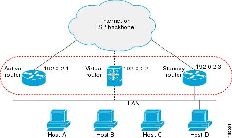
HSRP is a protocol that enables a group of routers to provide first-hop routing redundancy by selecting an active router and a standby router, ensuring continuous packet routing even if the active router fails.

  • Allows transparent failover of the first-hop IP router.

  • Provides redundancy for IP hosts on Ethernet networks with a default router IP address.

  • Uses a group of routers to select an active router (routes packets) and a standby router (takes over if the active fails).

Many host implementations do not support dynamic router discovery mechanisms but can be configured with a default router. HSRP provides failover services to these hosts, addressing administrative, processing, and security concerns associated with running dynamic router discovery on every host.

HSRP overview

HSRP (Hot Standby Router Protocol) is a redundancy protocol that allows a group of routers to share a virtual IP address and virtual MAC address , so that hosts can use a single default gateway for reliable network connectivity.

  • Routers in an HSRP group share a virtual IP address and virtual MAC address as the default gateway for hosts.

  • One router is elected as the active router to forward packets, while another is selected as the standby router to take over if the active router fails.

  • HSRP uses priority values and hello messages to determine active and standby roles and to detect failures.

HSRP operates by configuring a virtual IP and MAC address on each participating router interface. The active router handles traffic for the virtual addresses, while the standby router monitors the active router and takes over if it fails.

  • Each HSRP-enabled interface is configured with the same virtual IP and MAC address, and a unique real IP and MAC address.

  • Routers send and receive multicast UDP-based hello messages to detect failures and manage role transitions.

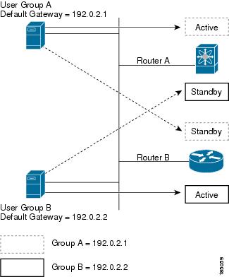
  • HSRP can support multiple groups on a single interface for additional redundancy.

  1. Configure the virtual IP and MAC address on all HSRP-enabled interfaces.

  2. Assign a higher priority to the interface you want to be the default active router (default priority is 100).

  3. HSRP selects the active and standby routers based on priority and hello message status.

  • Active router: Forwards packets sent to the virtual IP/MAC address.

  • Standby router: Monitors the active router and takes over if it fails.

  • Virtual router: Represents the shared default gateway for hosts, even though it does not physically exist.


Note


Packets destined for the HSRP virtual IP address on a routed port terminate on the local router, regardless of its HSRP role. On a Layer 2 (VLAN) interface, such packets terminate on the active router.


Figure 1. HSRP Topology with Two Enabled Routers


Example: HSRP in a Redundant Network

In a network with two routers configured for HSRP, both share a virtual IP and MAC address. Hosts are configured to use the virtual IP as their default gateway. If the active router fails to send hello messages within the configured time, the standby router automatically takes over, ensuring uninterrupted connectivity for hosts.

HSRP versions

  • HSRP version 1 is supported by default; interfaces can be configured to use HSRP version 2.

  • HSRP version 2 expands the group number range from 0–255 (version 1) to 0–4095.

  • HSRP version 2 uses different multicast and MAC address ranges, supports MD5 authentication, and introduces a TLV packet format.

HSRP version 2 introduces several enhancements over version 1, including expanded group numbers, updated multicast and MAC addresses, MD5 authentication, and a new packet format.

  • HSRP version 2 supports group numbers from 0 to 4095; version 1 supports 0 to 255.

  • For IPv4, HSRP version 2 uses multicast address 224.0.0.102; for IPv6, FF02::66. HSRP version 1 uses 224.0.0.2.

  • HSRP version 2 uses MAC address range 0000.0C9F.F000–0000.0C9F.FFFF for IPv4 and 0005.73A0.0000–0005.73A0.0FFF for IPv6. Version 1 uses 0000.0C07.AC00–0000.0C07.ACFF.

  • HSRP version 2 adds support for MD5 authentication.

  • HSRP version 2 uses a type-length-value (TLV) packet format; version 1 routers ignore version 2 packets.

  • Changing the HSRP version reinitializes the group due to a new virtual MAC address.

HSRP for IPv4

HSRP for IPv4 is a protocol that enables routers to provide a virtual default gateway for hosts, ensuring high availability and redundancy on a network segment.

  • Routers exchange HSRP hello packets using multicast addresses and UDP port 1985.

  • Hosts use the HSRP virtual IP and MAC addresses as their default gateway.

  • HSRP version 2 supports an expanded group number range and new multicast and MAC addresses.

How HSRP for IPv4 Works

HSRP routers communicate by exchanging hello packets to maintain the status of the active and standby routers. These packets are sent to specific multicast addresses and use UDP port 1985. The active router uses the HSRP virtual MAC address, while the standby router uses its interface MAC address. Hosts are configured to use the HSRP virtual IP address as their default gateway and resolve the associated virtual MAC address using ARP.

  • HSRP hello packets are sent to 224.0.0.2 (version 1) or 224.0.0.102 (version 2).

  • The active router sources hello packets from its configured IP and the HSRP virtual MAC address.

  • The standby router sources hello packets from its configured IP and the interface MAC address (BIA).

  • Hosts use ARP to resolve the HSRP virtual IP to the virtual MAC address.

  • HSRP group number determines the virtual MAC address (e.g., 0000.0C07.ACxy for version 1, 0000.0C9F.F000–0000.0C9F.FFFF for version 2).

HSRP for IPv6

HSRP for IPv6 is a protocol that provides a virtual first hop for IPv6 hosts, enabling rapid failover to an alternate default router in the event of a failure.

  • Offers faster switchover than standard IPv6 neighbor discovery, with failover in less than a second when using millisecond timers.

  • Provides a virtual IPv6 link-local address for hosts as the default gateway.

  • Uses a virtual MAC address and specific protocol parameters for group messaging and redundancy.

HSRP for IPv6 enhances the default router redundancy for IPv6 hosts by providing a virtual first hop and rapid failover capabilities.

  • HSRP for IPv6 provides a much faster switchover to an alternate default router than the IPv6 ND protocol provides.

  • When HSRP is configured on an IPv6 interface, periodic router advertisements (RAs) for the interface link-local address stop after a final RA with a router lifetime of zero is sent.

  • IPv6 ND sends periodic RAs for the HSRP virtual IPv6 link-local address when the HSRP group is active, and these RAs stop after a final RA is sent with a router lifetime of 0 when the group leaves the active state.

  • HSRP uses the virtual MAC address for active group messages only (hello, coup, and resign).

HSRP for IPv6 uses the following parameters:

  • HSRP version 2

  • UDP port 2029

  • Virtual MAC address range from 0005.73A0.0000 through 0005.73A0.0FFF

  • Multicast link-local IP destination address of FF02::66

  • Hop limit set to 255

HSRP for IPv6 addresses

An HSRP IPv6 group is defined by a virtual MAC address derived from the HSRP group number and a virtual IPv6 link-local address, which is by default derived from the HSRP virtual MAC address. The default virtual MAC address is always used to form the virtual IPv6 link-local address, regardless of the actual virtual MAC address used by the group.

  • Each HSRP IPv6 group has a virtual MAC address based on the group number.

  • The virtual IPv6 link-local address is derived from the default virtual MAC address.

  • The default virtual MAC address is always used to form the link-local address, even if the group uses a different MAC address.

HSRP for IPv6 uses specific MAC and IPv6 addresses for neighbor discovery and HSRP packets. The following table summarizes the MAC and IP addresses used for different packet types.

Table 1. HSRP and IPv6 ND Addresses

Packet

MAC Source Address

IPv6 Source Address

IPv6 Destination Address

Link-Layer Address Option

Neighbor solicitation (NS)

Interface MAC address

Interface IPv6 address

Interface MAC address

Router solicitation (RS)

Interface MAC address

Interface IPv6 address

Interface MAC address

Neighbor advertisement (NA)

Interface MAC address

Interface IPv6 address

Virtual IPv6 address

HSRP virtual MAC address

Route advertisement (RA)

Interface MAC address

Virtual IPv6 address

HSRP virtual MAC address

HSRP (inactive)

Interface MAC address

Interface IPv6 address

HSRP (active)

Virtual MAC address

Interface IPv6 address

HSRP does not add IPv6 link-local addresses to the Unicast Routing Information Base (URIB). Link-local addresses do not have secondary virtual IP addresses. For global unicast addresses, HSRP adds the virtual IPv6 address to the URIB and IPv6.

HSRP subnet VIP

An HSRP subnet virtual IP (VIP) is a virtual IP address that can be configured in a different subnet than the interface IP address.

  • Enables conservation of public IPv4 addresses by using a VIP as a public IP and an interface IP as a private IP.

  • Allows periodic ARP synchronization to vPC peers and ARP sourcing with the VIP when configured for hosts in the VIP subnet.

  • Not required for IPv6 addresses due to the larger address pool and routable IPv6 addresses on an SVI with regular HSRP.

You can configure HSRP subnet VIPs for Cisco Nexus 9508 platform switches with the 9636C-R, 9636C-RX, and 9636Q-R line cards.

HSRP authentication

HSRP authentication is a security mechanism that uses the MD5 algorithm to protect HSRP messages from spoofing and ensures message integrity by including the IPv4 or IPv6 address in the authentication TLVs.

  • Protects against HSRP-spoofing software.

  • Uses the industry-standard MD5 algorithm for authentication.

  • Includes IPv4 or IPv6 address in authentication TLVs for improved reliability and security.

HSRP messages

  • HSRP messages are multicast messages exchanged between routers configured with HSRP.

  • They convey HSRP priority and state information, and manage the transition between active and standby routers.

  • Key message types include Hello, Coup, and Resign.

Routers configured with HSRP exchange the following types of multicast messages:

  • Hello —The hello message conveys the HSRP priority and state information of the router to other HSRP routers.

  • Coup —When a standby router wants to assume the function of the active router, it sends a coup message.

  • Resign —The active router sends this message when it no longer wants to function as the active router.

HSRP load sharing

HSRP load sharing is a method that allows multiple HSRP groups to be configured on an interface, enabling traffic from connected hosts to be distributed across multiple routers while maintaining default router redundancy.

  • Supports configuration of multiple, overlapping HSRP groups on a single interface.

  • Enables load balancing of host traffic across two or more routers.

  • Maintains default router redundancy in case of router failure.

HSRP load sharing is achieved by configuring two overlapping IPv4 HSRP groups on an interface. Each router is active for one group and standby for the other, allowing traffic to be balanced between them. If one router fails, the other takes over both groups, ensuring continued connectivity.


Note


HSRP for IPv6 load balances by default. If two HSRP IPv6 groups are on the subnet, hosts learn of both groups from their router advertisements and choose to use one so that the load is shared between the advertised routers.


Figure 2. HSRP Load Sharing


Example of HSRP load sharing configuration

For example, in a network with two routers (A and B) and two HSRP groups, Router A is the active router for group A and standby for group B, while Router B is active for group B and standby for group A. This setup allows host traffic to be balanced across both routers. If either router fails, the remaining router processes traffic for both hosts.

Object tracking and HSRP

Object tracking is a mechanism that enables the modification of HSRP interface priority based on the operational state of another interface.

  • Allows dynamic adjustment of HSRP priority.

  • Supports tracking of the line protocol state of an interface or the reachability of an IP route.

  • Facilitates routing to a standby router if the main network interface fails.

You can use object tracking to modify the priority of an HSRP interface based on the operational state of another interface. If the specified object goes down, Cisco NX-OS reduces the HSRP priority by the configured amount.

Two objects that you can track are the line protocol state of an interface or the reachability of an IP route.

  • Line protocol state of an interface

  • Reachability of an IP route

For more information, see the Configuring HSRP Object Tracking section.

vPCs and HSRP

vPCs and HSRP integration enables redundancy and load balancing by allowing both the active and standby HSRP routers to forward traffic through physically separate switches that appear as a single logical port channel.

  • vPCs aggregate links from two Cisco Nexus 9000 Series switches to present as a single port channel.

  • HSRP provides active and standby router roles for high availability.

  • Both active and standby HSRP routers can forward traffic in a vPC topology.

How vPCs and HSRP Interoperate

HSRP interoperates with vPCs by allowing both the active and standby HSRP routers to forward traffic, providing redundancy and efficient traffic distribution.

  • Links from two Nexus 9000 Series switches appear as a single port channel to a third device.

  • HSRP active role can be distributed across primary and secondary vPC peers for different SVIs.

  1. Configure vPC between two Nexus 9000 Series switches.

  2. Enable HSRP on the relevant SVIs.

  3. Verify that both active and standby HSRP routers can forward traffic.

  • vPC: Aggregates links from two switches.

  • HSRP: Provides redundancy and failover.

For more information, see the Cisco Nexus 9000 Series NX-OS Layer 2 Switching Configuration Guide , Configuring the HSRP Priority section, and Configuration Examples for HSRP section.


Note


HSRP active can be distributed on both the primary and secondary vPC peers for different SVIs.


vPC peer gateway and HSRP

The vPC peer gateway is a feature that enables HSRP routers in a vPC environment to process packets addressed to the local vPC peer MAC address, the remote vPC peer MAC address, and the HSRP virtual MAC address directly.

  • Prevents third-party devices from causing packets to be sent across the vPC peer link using the source MAC address of an HSRP router.

  • Ensures packets addressed to the HSRP virtual MAC or vPC peer MAC addresses are handled locally by the correct router.

  • Reduces the risk of potential packet drops in vPC environments with HSRP.

Some third-party devices can ignore the HSRP virtual MAC address and instead use the source MAC address of an HSRP router. In a vPC environment, this behavior can cause packets to be sent across the vPC peer link, potentially resulting in dropped packets. Configuring the vPC peer gateway allows HSRP routers to directly handle these packets.

For more information, see the Cisco Nexus 9000 Series NX-OS Layer 2 Switching Configuration Guide .

BFD

BFD is a detection protocol that provides subsecond failure detection between two adjacent devices and can be less CPU-intensive than protocol hello messages.

  • Provides fast-forwarding and path-failure detection times.

  • Enables subsecond failure detection between adjacent devices.

  • Can offload some processing to the data plane on supported modules, reducing CPU usage.

BFD is supported for HSRP and can be less CPU-intensive than protocol hello messages because some of the BFD load can be distributed onto the data plane on supported modules.

For more information, see the Cisco Nexus 9000 Series NX-OS Interfaces Configuration Guide .

High availability and extended nonstop forwarding

  • HSRP supports stateful restarts, which occur when the HSRP process fails and is restarted.

  • HSRP supports stateful switchovers, which occur when the active supervisor switches to the standby supervisor.

  • Extended nonstop forwarding (NSF) allows HSRP to temporarily extend hold timers during a controlled switchover, preventing unnecessary state changes.

HSRP uses extended NSF to ensure continuous operation during supervisor switchovers by managing hold timers and hello messages.

  • HSRP applies the run-time configuration after a switchover.

  • When HSRP hold timers are configured for short periods, they might expire during a controlled switchover.

  • HSRP sends hello messages with extended timers when extended NSF is configured.

  • HSRP peers update their hold timers with the new extended values.

  • Extended timers prevent unnecessary HSRP state changes during the switchover.

  • After the switchover, HSRP restores the hold timers to their original configured values.

  • If the switchover fails, HSRP restores the hold timers after the extended hold timer values expire.

For more information, see the Configuring Extended Hold Timers for HSRP section.

Virtualization support

Virtualization support refers to the capability of HSRP to operate within virtual routing and forwarding (VRF) instances. HSRP can be configured to support multiple VRF instances.

Prerequisites for HSRP

You must enable the HSRP feature in a device before you can configure and enable any HSRP groups.

Guidelines and limitations for HSRP

Configure an IP address for the interface that you configure HSRP on and enable that interface before HSRP becomes active.

Cisco Nexus 9500 platform switches running in max-host routing mode do not support four-way HSRP.

Configure HSRP version 2 when you configure an IPv6 interface for HSRP.

For IPv4, the virtual IP address must be in the same subnet as the interface IP address.

Do not configure more than one first-hop redundancy protocol on the same interface.

HSRP version 2 does not interoperate with HSRP version 1. An interface cannot operate both version 1 and version 2 because both versions are mutually exclusive. However, the different versions can be run on different physical interfaces of the same router.

You cannot change from version 2 to version 1 if you have configured groups above the allowed group number range for version 1 (0-255).

HSRP for IPv4 is supported with BFD. HSRP for IPv6 is not supported with BFD.

If HSRP IPv4 and IPv6 use the same virtual MAC address on an SVI, the HSRP state must be the same for both HSRP IPv4 and IPv6. The priority and preemption should be configured to result in the same state after failovers.

Cisco NX-OS removes all Layer 3 configurations on an interface when you change the interface VRF membership, port channel membership, or the port mode to Layer 2.

If you configure virtual MAC addresses with vPC, you must configure the same virtual MAC address on both vPC peers.

You cannot use the HSRP MAC address burned-in option on a VLAN interface that is a vPC member.

Cisco NX-OS supports having the same HSRP groups on all nodes in a double-sided vPC.

If you have not configured authentication, the show hsrp command displays the following string:

Authentication text "cisco"

The default behavior of HSRP is as defined in RFC 2281:

If no authentication data is configured, the RECOMMENDED default
					value is 0x63 0x69 0x73 0x63 0x6F 0x00 0x00 0x00.

When configuring 4-way HSRP using 2 pairs of vPC switches (new deployment or migration scenarios), the HSRP priorities should be configured such that the vPC pairs of Nexus 9000 switches are in Active/Standby state and Listen/Listen state. There is no support for Cisco Nexus 9000 vPC peers to be in HSRP Active/Listen state, or Standby/Listen state.

HSRP subnet VIP feature guidelines and limitations

The HSRP subnet VIP feature has the following guidelines and limitations:

  • This feature is supported for Cisco Nexus 9000 Series switches and for Cisco Nexus 9508 switches with the 9636C-R, 9636C-RX, and 9636Q-R line cards.

  • This feature is supported only for IPv4 addresses and only in a vPC topology.

  • Primary or secondary VIPs can be subnet VIPs, but subnet VIPs must not overlap any interface subnet.

  • Regular host VIPs use a mask length of 0 or 32. If you specify a mask length for a subnet VIP, it must be greater than 0 and less than 32.

  • Unicast Reverse Path Forwarding (URPF) and DHCP sourcing with VIPs are not supported with this feature.

  • This feature does not support using a DHCP relay agent to relay DHCP packets with a VIP as the source.

  • VIP direct routes must be explicitly advertised to routing protocols using redistribute commands and route maps.

  • Supervisor-generated traffic (pings, trace routes, and so on) destined for VIP subnets continues to source with SVI IP addresses and not with the VIP.

  • If the subnet VIP is configured with /32 as the length, you must use the no command with /32 to remove the IP address (for example, no ip ip-address/32 ).

To remove an SVI configuration with its sub-configurations, that are configured using a configuration profile, you must first remove the profile or clear the manual configuration settings under the VLAN before executing no interface vlan command.

Configuration guidelines to enforce the pre-empt reload timer

The following are configuration guidelines to enforce the pre-empt reload timer. The guidelines are listed in order of decreasing preference.

  1. In triangle topologies, we recommend that the HSRP peers are configured within a single VPC domain. This configuration prevents the Spanning-Tree root bridge from changing on the HSRP peer when the Cisco Nexus 9000 configuration is reloaded.

  2. Make sure the Spanning Tree root bridge for all VLANs is not on the Cisco Nexus 9000 that is being reloaded.

  3. If 1 and 2 are not possible, make sure that the switch has an enabled link for all the SVI VLANs that is connected to another switch that is not the HSRP peer.

Default settings for HSRP parameters

This topic provides the default values for HSRP parameters.

Default HSRP parameters

Parameters

Default

HSRP

Disabled

Authentication

Enabled as text for version 1, with cisco as the password

HSRP version

Version 1

Preemption

Disabled

Priority

100

Virtual MAC address

Derived from HSRP group number

Configue HSRP

Enable HSRP

You must globally enable HSRP before you can configure and enable any HSRP groups.

Procedure


[ no ] feature hsrp

Example:

switch(config)# feature hsrp

Enables the HSRP feature. Use the no form of this command to disable HSRP for all groups.


Configure the HSRP version

You can configure the HSRP version. If you change the version for existing groups, Cisco NX-OS reinitializes HSRP for those groups because the virtual MAC address changes. The HSRP version applies to all groups on the interface.


Note


IPv6 HSRP groups must be configured as HSRP version 2.


Procedure


hsrp version {1 | 2}

Example:

switch(config-if)# hsrp version 2

Confirms the HSRP version. Version 1 is the default.


Configure an HSRP group for IPv4

Use this task to configure an HSRP group for IPv4 on an interface.

You can configure an HSRP group on an IPv4 interface and configure the virtual IP address and virtual MAC address for the HSRP group.

Before you begin

Ensure that you have enabled the HSRP feature (see the Enabling HSRP section).

Cisco NX-OS enables an HSRP group once you configure the virtual IP address. You must configure HSRP attributes such as authentication, timers, and priority before you enable the HSRP group.

Procedure


Step 1

configure terminal

Example:

switch# configure terminal
switch(config)#
					

Enters global configuration mode.

Step 2

interface interface-type slot/port

Example:

switch(config)# interface ethernet 1/2
switch(config-if)# 

Enters interface configuration mode.

Step 3

ip ip-address/length

Example:

switch(config-if)# ip 192.0.2.2/8

Configures the IPv4 address of the interface.

Step 4

hsrp group-number [ ipv4 ]

Example:

switch(config-if)# hsrp 2
switch(config-if-hsrp)#

Creates an HSRP group and enters HSRP configuration mode. The range for HSRP version 1 is from 0 to 255. The range for HSRP version 2 is from 0 to 4095. The default value is 0.

Step 5

ip [ ip-address [ secondary ]]

Example:

switch(config-if-hsrp)# ip 192.0.2.1

Configures the virtual IP address for the HSRP group and enables the group. This address should be in the same subnet as the IPv4 address of the interface.

Step 6

exit

Example:

switch(config-if-hsrp)# exit

Exits HSRP configuration mode.

Step 7

no shutdown

Example:

switch(config-if-hsrp)# no shutdown

Enables the interface.

Step 8

(Optional) show hsrp [ group group-number ] [ ipv4 ]

Example:

switch(config-if-hsrp)# show hsrp group 2

Displays HSRP information.

Step 9

(Optional) copy running-config startup-config

Example:

switch(config-if-hsrp)# copy running-config startup-config
					

Copies the running configuration to the startup configuration.


After completing these steps, the HSRP group is configured and enabled on the interface.


Note


You should use the no shutdown command to enable the interface after you finish the configuration.


This example shows how to configure an HSRP group on Ethernet 1/2:

switch# configure terminal
switch(config)# interface ethernet 1/2
switch(config-if)# ip 192.0.2.2/8
switch(config-if)# hsrp 2
switch(config-if-hsrp)# ip 192.0.2.1
switch(config-if-hsrp)# exit
switch(config-if)# no shutdown
switch(config-if)# copy running-config startup-config

Configure an HSRP group for IPv6

Use this task to configure an HSRP group for IPv6 on an interface.

You can configure an HSRP group on an IPv6 interface and configure the virtual MAC address for the HSRP group.

When you configure an HSRP group for IPv6, HSRP generates a link-local address from the link-local prefix. HSRP also generates a modified EUI-64 format interface identifier in which the EUI-64 interface identifier is created from the relevant HSRP virtual MAC address.

Before you begin

You must enable HSRP (see the Enabling HSRP section).

Ensure that you have enabled HSRP version 2 on the interface on which you want to configure an IPv6 HSRP group.

Ensure that you have configured HSRP attributes such as authentication, timers, and priority before you enable the HSRP group.

Procedure


Step 1

configure terminal

Example:

switch# configure terminal
switch(config)#
					

Enters global configuration mode.

Step 2

interface interface-type slot/port

Example:

switch(config)# interface ethernet 3/2
switch(config-if)#

Enters interface configuration mode.

Step 3

ipv6 address ipv6-address/length

Example:

switch(config-if)# ipv6 address 2001:0DB8::0001:0001/64

Configures the IPv6 address of the interface.

Step 4

hsrp version 2

Example:

switch(config-if-hsrp)# hsrp version 2

Configures the group for HSRP version 2.

Step 5

hsrp group-number ipv6

Example:

switch(config-if)# hsrp 10 ipv6
switch(config-if-hsrp)#

Creates an IPv6 HSRP group and enters HSRP configuration mode. The range for HSRP version 2 is from 0 to 4095. The default value is 0.

Step 6

ip ipv6-address

Example:

switch(config-if-hsrp)# ip 2001:DB8::1

Configures the virtual IPv6 address for the HSRP group and enables the group.

Step 7

ip autoconfig

Example:

switch(config-if-hsrp)# ip autoconfig

Autoconfigures the virtual IPv6 address for the HSRP group from the calculated link-local virtual IPv6 address and enables the group.

Step 8

exit

Example:

switch(config-if-hsrp)# exit
switch(config-if)#

Exits HSRP configuration mode.

Step 9

no shutdown

Example:

switch(config-if)# no shutdown

Enables the interface.

Step 10

(Optional) show hsrp [ group group-number ] [ ipv6 ]

Example:

switch(config-if)# show hsrp group 10

Displays HSRP information.

Step 11

copy running-config startup-config

Example:

switch(config-if)# copy running-config startup-config
					

Copies the running configuration to the startup configuration.


Note


You should use the no shutdown command to enable the interface after you finish the configuration.


This example shows how to configure an IPv6 HSRP group on Ethernet 3/2:

switch# configure terminal
switch(config)# interface ethernet 3/2
switch(config-if)# ipv6 address 2001:0DB8::0001:0001/64
switch(config-if-hsrp)# hsrp version 2
switch(config-if)# hsrp 2 ipv6
switch(config-if-hsrp)# ip 2001:DB8::1
switch(config-if-hsrp)# exit
switch(config-if)# no shutdown
switch(config-if)# copy running-config startup-config

Configure the HSRP virtual MAC address

You can override the default virtual MAC address that HSRP derives from the configured group number.


Note


You must configure the same virtual MAC address on both vPC peers of a vPC link.


Procedure


Step 1

mac-address string

Example:

switch(config-if-hsrp)# mac-address 5000.1000.1060

Configures the virtual MAC address for an HSRP group. The string uses the standard MAC address format (xxxx.xxxx.xxxx).

Step 2

(Optional) hsrp use-bia [scope interface ]

Example:

switch(config-if)# hsrp use-bia

Note


To configure HSRP to use the burned-in MAC address of the interface for the virtual MAC address, use the following command in interface configuration mode:

Configures HSRP to use the burned-in MAC address of the interface for the HSRP virtual MAC address. You can optionally configure HSRP to use the burned-in MAC address for all groups on this interface by using the scope interface keyword.


Authenticate HSRP

Use this task to configure authentication for HSRP, ensuring secure protocol operation on your network devices.

You can configure HSRP to authenticate the protocol using cleartext or MD5 digest authentication. MD5 authentication uses a keychain. For more details, see the Cisco Nexus 9000 Series NX-OS Security Configuration Guide .

Before you begin

You must enable HSRP (see the Enabling HSRP section).

Ensure that you have configured the same authentication and keys on all members of the HSRP group.

Ensure that you have created the keychain if you are using MD5 authentication.

Procedure


Step 1

configure terminal

Example:

switch# configure terminal
switch(config)#
					

Enters global configuration mode.

Step 2

interface interface-type slot/port

Example:

switch(config)# interface ethernet 1/2
switch(config-if)# 

Enters interface configuration mode.

Step 3

hsrp group-number [ ipv4 | ipv6 ]

Example:

switch(config-if)# hsrp 2
switch(config-if-hsrp)#

Creates an HSRP group and enters HSRP configuration mode.

Step 4

authentication { text string | md5 { key-chain key-chain | key-string { 0 | 7 } text [ compatibility ] [ timeout seconds ]}}

Example:

switch(config-if-hsrp)# authentication text mypassword

Example:

switch(config-if-hsrp)# authentication md5 key-chain hsrp-keys

Configures cleartext authentication for HSRP on this interface using the authentication text command or configures MD5 authentication for HSRP on this interface using the authentication md5 command.

If you configure MD5 authentication, you can use a keychain or key string. If you use a key string, you can optionally set the timeout for when HSRP only accepts a new key. The range is from 0–32,767 seconds.

Compatibility: Designed for authentication compatibility between Cisco IOS and Cisco NX-OS. Compatibility mode is for MD5 key-string authentication. When a hidden authentication type is configured on both Cisco IOS and Cisco NX-OS, the compatibility flag has to be enabled in NX-OS to bring up the HSRP session.

Step 5

(Optional) show hsrp [ group group-number ]

Example:

switch(config-if-hsrp)# show hsrp group 2

Displays HSRP information.

Step 6

(Optional) copy running-config startup-config

Example:

switch(config-if-hsrp)# copy running-config startup-config
					

Copies the running configuration to the startup configuration.


HSRP authentication is configured. The device will use the specified authentication method for HSRP group communication.

This example shows how to configure MD5 authentication for HSRP on Ethernet 1/2 after creating the keychain:

switch# configure terminal
switch(config)# key chain hsrp-keys
switch(config-keychain)# key 0
switch(config-keychain-key)# key-string 7 zqdest
switch(config-keychain-key) accept-lifetime 00:00:00 Jun 01 2013 23:59:59 Sep 12 2013
switch(config-keychain-key) send-lifetime 00:00:00 Jun 01 2013 23:59:59 Aug 12 2013
switch(config-keychain-key) key 1
switch(config-keychain-key) key-string 7 uaeqdyito
switch(config-keychain-key) accept-lifetime 00:00:00 Aug 12 2013 23:59:59 Dec 12 2013
switch(config-keychain-key) send-lifetime 00:00:00 Sep 12 2013 23:59:59 Nov 12 2013
switch(config-keychain-key)# interface ethernet 1/2
switch(config-if)# hsrp 2
switch(config-if-hsrp)# authentication md5 key-chain hsrp-keys
switch(config-if-hsrp)# copy running-config startup-config

Configure HSRP object tracking

You can configure an HSRP group to adjust its priority based on the availability of other interfaces or routes. The priority of an HSRP group can change dynamically if it has been configured for object tracking and the object that is being tracked goes down.

The tracking process periodically polls the tracked objects and notes any value change. The value change triggers HSRP to recalculate the priority. The HSRP interface with the higher priority becomes the active router if you configure the HSRP interface for preemption.

Procedure


Step 1

configure terminal

Example:

switch# configure terminal
switch(config)#
					

Enters global configuration mode.

Step 2

track object-id interface interface-type slot/port { line-protocol | ip routing | ipv6 routing }

Example:

switch(config)# track 1 interface ethernet 2/2 line-protocol
switch(config-track)#

Configures the interface that the track object tracks. Changes in the state of the interface affect the track object status as follows:

  • You configure the interface and corresponding object number that you use with the track command in global configuration mode.

  • The line-protocol keyword tracks whether the interface is up. The ip routing or ipv6 routing keyword also checks that IP routing is enabled on the interface and an IP address is configured.

Step 3

track object-id { ip | ipv6 } route ip-prefix/length reachability

Example:

switch(config-track)# track 2 ip route 192.0.2.0/8 reachability

Creates a tracked object for a route and enters tracking configuration mode. The object-id range is from 1 to 500.

Step 4

exit

Example:

switch(config-track)# exit
switch(config)#
					

Exits track configuration mode.

Step 5

interface interface-type slot/port

Example:

switch(config)# interface ethernet 1/2
switch(config-if)# 

Enters interface configuration mode.

Step 6

hsrp group-number [ ipv4 | ipv6 ]

Example:

switch(config-if)# hsrp 2
switch(config-if-hsrp)#

Creates an HSRP group and enters HSRP configuration mode.

Step 7

priority [ value ]

Example:

switch(config-if-hsrp)# priority 254

Sets the priority level used to select the active router in an HSRP group. The range is from 0 to 255. The default is 100.

Step 8

track object-id [ decrement value ]

Example:

switch(config-if-hsrp)# track 1 decrement 20

Specifies an object to be tracked that affects the weighting of an HSRP interface.

The value argument specifies a reduction in the priority of an HSRP interface when a tracked object fails. The range is from 1 to 255. The default is 10.

Step 9

preempt [ delay [ minimum seconds ] [ reload seconds ] [ sync seconds ]]

Example:

switch(config-if-hsrp)# preempt delay minimum 60

Configures the router to take over as the active router for an HSRP group if it has a higher priority than the current active router. This command is disabled by default. Optionally, a delay can be configured that delays the HSRP group preemption by the configured time. The range is from 0 to 3600 seconds.

Step 10

(Optional) show hsrp interface interface-type slot/port

Example:

switch(config-if-hsrp)# show hsrp interface ethernet 1/2

Displays HSRP information for an interface.

Step 11

copy running-config startup-config

Example:

switch(config-if-hsrp)# copy running-config startup-config
					

Copies the running configuration to the startup configuration.


This example shows how to configure HSRP object tracking on Ethernet interface 1/2:

switch# configure terminal
switch(config)# track 1 interface ethernet 2/2 line-protocol
switch(config-track)# track 2 ip route 192.0.2.0/8 reachability
switch(config-track)# exit
switch(config)# interface ethernet 1/2
switch(config-if)# hsrp 2
switch(config-if-hsrp)# priority 254
switch(config-if-hsrp)# track 1 decrement 20
switch(config-if-hsrp)# preempt delay minimum 60
switch(config-if-hsrp)# copy running-config startup-config

Configure the HSRP priority

You can configure the priority of an HSRP group. HSRP uses the priority to determine which HSRP group member acts as the active router. If you configure HSRP on a vPC-enabled interface, you can optionally configure the upper and lower threshold values to control when to fail over to the vPC trunk. If the standby router priority falls below the lower threshold, HSRP sends all standby router traffic across the vPC trunk to forward through the active HSRP router. HSRP maintains this scenario until the standby HSRP router priority increases above the upper threshold.

For IPv6 HSRP groups, if all group members have the same priority, HSRP selects the active router based on the IPv6 link-local address.

To configure the HSRP priority, use the following command in the HSRP group configuration mode:

Procedure


priority level [ forwarding-threshold lower lower-value upper upper-value ]

Example:

switch(config-if-hsrp)# priority 60 forwarding-threshold lower 40 upper 50

Sets the priority level used to select the active router in an HSRP group. The level range is from 0 to 255. The default is 100. Optionally, this command sets the upper and lower threshold values used by vPC to determine when to fail over to the vPC trunk. The lower-value range is from 1 to 255. The default is 1. The upper-value range is from 1 to 255. The default is 255.


Customize HSRP in HSRP configuration mode

You can optionally customize the behavior of HSRP. Be aware that as soon as you enable an HSRP group by configuring a virtual IP address, that group becomes operational. If you enable an HSRP group before customizing HSRP, the router could take control over the group and become the active router before you finish customizing the feature. If you plan to customize HSRP, you should do so before you enable the HSRP group.

Procedure


Step 1

(Optional) name string

Example:

switch(config-if-hsrp)# name HSRP-1

Specifies the IP redundancy name for an HSRP group. The string is from 1 to 255 characters. The default string has the following format: hsrp- interface short-name group-id . For example, hsrp-Eth2/1-1.

Step 2

(Optional) preempt [ delay [ minimum seconds ] [ reload seconds ] [ sync seconds ]]

Example:

switch(config-if-hsrp)# preempt delay minimum 60

Configures the router to take over as an active router for an HSRP group if it has a higher priority than the current active router. This command is disabled by default. Optionally, a delay can be configured that delays the HSRP group preemption by the configured time. The range is from 0 to 3600 seconds.

Step 3

(Optional) timers [ msec ] hellotime [ msec ] holdtime

Example:

switch(config-if-hsrp)# timers 5 18

Configures the hello and hold time for this HSRP member as follows:

  • hellotime —The interval between successive hello packets sent. The range is from 1 to 254 seconds.

  • holdtime —The interval before the information in the hello packet is considered invalid. The range is from 3 to 255.

The optional msec keyword specifies that the argument is expressed in milliseconds instead of the default seconds. The timer ranges for milliseconds are as follows:

  • hellotime —The interval between successive hello packets sent. The range is from 250 to 999 milliseconds.

  • holdtime —The interval before the information in the hello packet is considered invalid. The range is from 750 to 3000 milliseconds.

Step 4

(Optional) hsrp delay minimum seconds

Example:

switch(config-if)# hsrp delay minimum 30

Specifies the minimum amount of time that HSRP waits after a group is enabled before participating in the group. The range is from 0 to 10000 seconds. The default is 0.

Step 5

(Optional) hsrp delay reload seconds

Example:

switch(config-if)# hsrp delay reload 30

Specifies the minimum amount of time that HSRP waits after a reload and before participating in the group. The range is from 0 to 10000 seconds. The default is 0.

Note


When using preempt delay with 'reload' option, the recommendation is to use it along with hsrp delay reload (interface-level command). This is to avoid the scenario where after reload, higher priority HSRP Standby becomes Active on hold timer expiry (10 seconds) because the preempt delay reload timer didn't start as SVI is UP but the physical link/port-channel is not yet UP after reload. Timers can be tuned according to scale.

Example - Instead of configuring preempt delay reload 200 , configure preempt delay reload 140 and hsrp delay reload 60 . This is to ensure that the SVI and physical link/port-channel are both UP, when HSRP starts the start machine from INIT state after reload delay expiry (60 sec).


Customize HSRP in interface configuration mode

You can optionally customize the behavior of HSRP. Be aware that as soon as you enable an HSRP group by configuring a virtual IP address, that group becomes operational. If you enable an HSRP group before customizing HSRP, the router could take control over the group and become the active router before you finish customizing the feature. If you plan to customize HSRP, you should do so before you enable the HSRP group.

Procedure


Step 1

configure terminal

Example:

switch# configure terminal
switch(config)#
					

Enters global configuration mode.

Step 2

interface interface-type slot/port

Example:

switch(config)# interface ethernet 1/2
switch(config-if)# 

Enters interface configuration mode.

Step 3

hsrp delay minimum seconds

Example:

switch(config-if)# hsrp delay minimum 30

Specifies the minimum amount of time that HSRP waits after a group is enabled before participating in the group. The range is from 0 to 10000 seconds. The default is 0.

Step 4

hsrp delay reload seconds

Example:

switch(config-if)# hsrp delay reload 30

Specifies the minimum amount of time that HSRP waits after a reload and before participating in the group. The range is from 0 to 10000 seconds. The default is 0.

Step 5

(Optional) copy running-config startup-config

Example:

switch(config-if)# copy running-config startup-config
					

Copies the running configuration to the startup configuration.


Configure extended hold timers for HSRP

You can configure HSRP to use extended hold timers to support extended NSF during a controlled (graceful) switchover. You should configure extended hold timers on all HSRP routers.


Note


You must configure extended hold timers on all HSRP routers if you configure extended hold timers. If you configure a nondefault hold timer, you should configure the same value on all HSRP routers when you configure HSRP extended hold timers.


Note


HSRP extended hold timers are not applied if you configure millisecond hello and hold timers for HSRPv1. This statement does not apply to HSRPv2.


Procedure


Step 1

(Optional) hsrp timers extended-hold [ timer ]

Example:

switch(config)# hsrp timers extended-hold

Sets the HSRP extended hold timer in seconds for both IPv4 and IPv6 groups. The timer range is from 10 to 255. The default is 10.

Note


Use the show hsrp command or the show running-config hsrp command to display the extended hold time.

Step 2

(Optional) show hsrp

Example:

switch(config)# show hsrp

Displays the HSRP extended hold time.


Use the show hsrp command or the show running-config hsrp command to display the extended hold time.

Verify the HSRP Configuration

To display HSRP configuration information, perform one of the following tasks.

Command

Purpose

show hsrp [ group group-number ]

Displays the HSRP status for all groups or one group.

show hsrp delay [ interface interface-type slot/port ]

Displays the HSRP delay value for all interfaces or one interface.

show hsrp [ interface interface-type slot/port ]

Displays the HSRP status for an interface.

show hsrp [ group group-number ] [ interface interface-type slot/port ] [ active ] [ all ] [ init ] [ learn ] [ listen ] [ speak ] [ standby ]

Displays the HSRP status for a group or interface for virtual forwarders in the active, init, learn, listen, or standby state. Use the all keyword to see all states, including disabled.

show hsrp [ group group-number ] [ interface interface-type slot/port ] [ active ] [ all ] [ init ] [ learn ] [ listen ] [ speak ] [ standby ] brief

Displays a brief summary of the HSRP status for a group or interface for virtual forwarders in the active, init, learn, listen, or standby state. Use the all keyword to see all states, including disabled.

show ip local-pt

Displays whether the netstack has programmed a subnet route for the VIP subnet.

Configuration examples for HSRP

  • HSRP can be enabled on interfaces with MD5 authentication and interface tracking.

  • HSRP priority can be configured and adjusted using the priority and track commands.

  • HSRP subnet VIP addresses must not be in the same subnet as the interface IP address to avoid configuration errors.

HSRP Configuration Reference

These examples demonstrate how to configure HSRP with authentication, interface tracking, priority, and VIP address settings.

Examples

Enable HSRP with MD5 authentication and interface tracking:
key chain hsrp-keys
key 0
key-string 7 zqdest
accept-lifetime 00:00:00 Jun 01 2013 23:59:59 Sep 12 2013
send-lifetime 00:00:00 Jun 01 2013 23:59:59 Aug 12 2013
key 1
key-string 7 uaeqdyito
accept-lifetime 00:00:00 Aug 12 2013 23:59:59 Nov 12 2013
send-lifetime 00:00:00 Sep 12 2013 23:59:59 Nov 12 2013
feature hsrp
track 2 interface ethernet 2/2 ip
interface ethernet 1/2
ip address 192.0.2.2/8
hsrp 1
authenticate md5 key-chain hsrp-keys
priority 90
track 2 decrement 20
ip 192.0.2.10
no shutdown
			
Configure HSRP priority on an interface:
interface vlan 1
hsrp 0
preempt
priority 100 forwarding-threshold lower 80 upper 90
ip 192.0.2.2
track 1 decrement 30
			
Configure an HSRP subnet VIP address in a different subnet than the interface IP address:
sswitch# configure terminal
switch(config)# feature hsrp
switch(config)# feature interface-vlan
switch(config)# interface vlan 2
switch(config-if)# ip address 192.0.2.1/24
switch(config-if)# hsrp 2
switch(config-if-hsrp)# ip 209.165.201.1/24
Example of VIP subnet mismatch error:
switch# configure terminal
switch(config)# feature hsrp
switch(config)# feature interface-vlan
switch(config)# interface vlan 2
switch(config-if)# ip address 192.0.2.1/24
switch(config-if)# hsrp 2
switch(config-if-hsrp)# ip 209.165.201.1
!ERROR: VIP subnet mismatch with interface IP!
Example of error when VIP is in the same subnet as the interface IP address:
switch# configure terminal
switch(config)# feature hsrp
switch(config)# feature interface-vlan
switch(config)# interface vlan 2
switch(config-if)# ip address 192.0.2.1/24
switch(config-if)# hsrp 2
switch(config-if-hsrp)# ip 192.0.2.10/24
!ERROR: Subnet VIP cannot be in same subnet as interface IP!

Additional references

  • This topic provides references to related documents and MIBs for HSRP implementation.

Additional HSRP Reference Information

For additional information related to implementing HSRP, see the following sections: