
Intersite L3Out with PBR
Cisco Application Centric Infrastructure (ACI) policy-based redirect (PBR) enables traffic redirection for service appliances, such as firewalls or load balancers, and intrusion prevention system (IPS). Typical use cases include provisioning service appliances that can be pooled, tailored to application profiles, scaled easily, and have reduced exposure to service outages. PBR simplifies the insertion of service appliances by using contract between the consumer and provider endpoint groups even if they are all in the same virtual routing and forwarding (VRF) instance.
PBR deployment consists of configuring a route redirect policy and a cluster redirect policy, and creating a service graph template that uses these policies. After the service graph template is deployed, you can attach it to a contract between EPGs so that all traffic following that contract is redirected to the service graph devices based on the PBR policies you have created. Effectively, this allows you to choose which type of traffic between the same two EPGs is redirected to the L4-L7 device, and which is subject to a security policy applied at the fabric level.
More in-depth information specific to services graphs and PBR is available in the Cisco APIC Layer 4 to Layer 7 Services Deployment Guide
Configuration Workflow
The use cases described in the following sections are an extension of a basic intersite L3Out (without PBR) use case which is in turn an extension on basic external connectivity (L3Out) configuration in each site. The workflow to configure the supported use cases is the same, with the only differences being whether you create the objects in the same or different VRFs (intra-VRF vs inter-VRF) and where you deploy the objects (stretched vs non-stretched).
-
Configure basic external connectivity (L3Out) for each site.
The intersite L3Out with PBR configuration described in the following sections is built on top of existing external connectivity (L3Out) in each site. If you have not configured an L3Out, create and deploy one as described in the External Connectivity (L3Out) chapter before proceeding with the following sections.
-
Configure an intersite L3Out use case without PBR.
We recommend configuring a simple intersite L3Out use case without any policy-based redirection before adding service chaining to it. This is described in detail in the Intersite L3Out chapter.
-
Add service chaining to the L3Out contract as described in the following sections, which includes:
-
Adding an external TEP pool for each Pod in each site where intersite L3Out is deployed.
-
Creating a Service Device template and assigning it to sites.
The service device template must be assigned to the same sites as the L3Out and application templates that contain other configuration objects.
-
Providing site-level configurations for the Service Device template.
Each site can have its own service device configuration including different high-availability models (such as active/active, active/standby, or independent service nodes).
-
Associating the service device you defined to the contract used for the basic intersite L3Out use case you deployed in the previous step.
-
Supported Use Cases
The following diagrams illustrate the traffic flows between an ACI internal endpoint in application EPG and an external endpoint through the L3Out in another site in the supported intersite L3Out with PBR use cases.
Intra-VRF vs Inter-VRF
When creating and configuring the application EPG and the external EPG, you will need to provide a VRF for the application EPG’s bridge domain and for the L3Out. You can choose to use the same VRF (intra-VRF) or different VRFs (inter-VRF).
When establishing a contract between the EPGs, you will need to designate one EPG as the provider and the other one as the consumer:
-
When both EPGs are in the same VRF, either one can be the consumer or the provider.
-
If the EPGs are in different VRFs, the external EPG must be the provider and the application EPG must be the consumer.
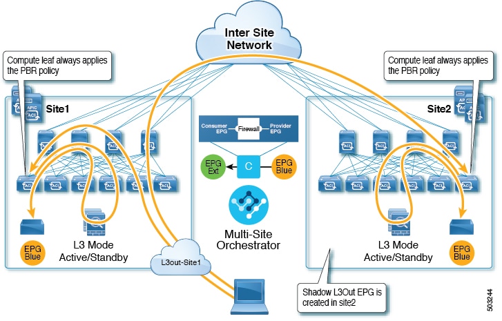
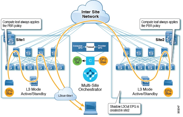
L3Out to Stretched EPG
This use case illustrates a single application EPG that is stretched between two sites and a single L3Out created in only one of the sites. Regardless of whether the application EPG’s endpoint is in the same site as the L3Out or the other site, traffic will go through the same L3Out. However, the traffic will always go through the service node that is local to the endpoint’s site because for North-South traffic the PBR policy is always applied only on the compute leaf nodes (and not on the border leaf nodes).

The same flow applies in cases when the external EPG is stretched and each site has its own L3Out, but the L3Out in the site where the traffic is originating or is destined to is down.
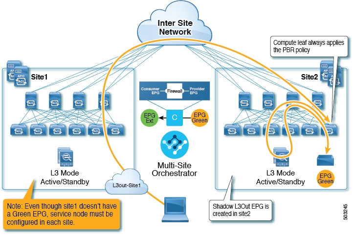
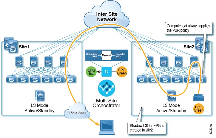
L3Out to Site-Local EPG
This use case illustrates a site-local application EPG that will use the L3Out in the other site for North-South traffic. Like in the previous example, all traffic will use the EPG’s site-local service graph device.
The same flow applies in cases where the external EPG is stretched and each site has its own L3Out, but the EPG’s local L3Out is down.
Guidelines and Limitations
When configuring an Intersite L3Out with PBR, the following restrictions apply:
-
When configuring MultiSite Policy-Based Redirect (PBR) between Endpoint Groups (EPGs), the following features are not supported for specific IP endpoints or host prefixes (/32 for IPv4 and /128 for IPv6):
-
Static Route on a Bridge Domain (NH Reachability)
-
Microsoft Network Load Balancing
-
Anycast MAC
-
-
For intersite L3Out with PBR, the following use cases are supported:
-
Inter-VRF intersite L3Out with the application EPG as the
consumer.For inter-VRF contracts, the External EPG associated to the L3Out must be the
provider.This use case is supported for sites running Cisco APIC release 4.2(5) and later or release 5.1(x), it is not supported for APIC release 5.0(x).
-
Intra-VRF intersite L3Out with the application EPG as either the
provideror theconsumerThis use case is supported for sites running Cisco APIC release 4.2(5) and later or release 5.1(x), it is not supported for APIC release 5.0(x).
-
-
For EPG-to-L3Out use cases, the application EPG can be stretched or site-local.
-
For EPG-to-L3Out use cases, both one-arm and two-arm deployment models are supported; for L3Out-to-L3Out use case, only one-arm firewall devices are supported.
In one-arm deployment, both the inside and outside interfaces of the service graph are connected to the same bridge domain. In two-arm deployments, the service graph interfaces are connected to separate BDs.
-
For EPG-to-L3Out use cases, when configuring a load balancer with PBR, the load balancer and the real servers for the virtual IP (VIP) must be in the same site. If PBR is disabled, the load balancer and the real servers can be in different sites.
L3Out-to-L3Out case does not support load balancers.
-
You must have the basic use case of intersite L3Out already configured before you insert a service device by enabling service chaining on the contract that is already configured between an L3Out in one site and an EPG in another site or between two L3Outs in different sites.
Detailed instructions on deploying an intersite L3Out without PBR are described in the Intersite L3Out chapter.
Create Service Device Template
-
Ensure that you have read and completed the requirements described in Guidelines and Limitations.
This section describes how to configure one or more devices for a service graph.
-
Log in to the Nexus Dashboard Orchestrator GUI.
-
From the left navigation pane, select ConfigureTenant Templates.
-
Choose the Service Device tab.
-
Create a Service Device template and associate it with the sites.
-
From Configure > Tenant Templates, choose the Service Device tab.
-
Click Create Service Device Template.
-
In the template properties sidebar that opens, provide the Name for the template and Select a Tenant.
-
In the Template Properties page, choose ActionsAdd/Remove Sites and associate the template with both sites.
-
Click Save to save the template.
-
-
Create and configure the device cluster.
-
In the Template Properties page (template-level configuration), choose Create Object > Service Device Cluster.
The device cluster defines the service for which you want to redirect traffic.
-
In the <cluster-name> sidebar, provide the Name for the cluster.
The Device Location and Device Mode are pre-populated based on the currently supported use case.
-
Choose the Device Type.
-
For Device Mode, choose
L3. -
Chose the Connectivity Mode.
If you are configuring an L3Out-to-L3Out use case, you must use
One Arm
-
Provide the Interface Name.
-
For the Interface Type, choose
BD.For vzAny use cases, this release supports attaching the service device to a bridge domain only.
-
Click Select BD > to choose the service bridge domain to which you want to attach this device.
This is the stretched service BD you created in the previous section, for example
FW-external. -
For the Redirect option, choose
Yes.You must choose to enable redirect for the PBR use case. After choosing
Yes, the IP SLA Monitoring Policy option becomes available. -
(Optional) Click Select IP SLA Monitoring Policy and choose an IP SLA policy if you had created one.
-
(Optional) In the Advanced Settings area, choose Enable if you want to provide additional settings for the service cluster.
You can configure the following advanced settings:
-
QoS Policy - allows you assign a specific QoS level within the ACI fabrics for the redirected traffic.
-
Preferred Group - specifies whether or not this service cluster is part of the preferred group.
-
Load Balancing Hashing - allows you to specify the hashing algorithm for PBR load balancing.
For additional information, see ACI Policy-Based Redirect Service Graph Design.
-
Pod Aware Redirection - can be configured in Multi-Pod configuration if you want to specify the preferred PBR node. When you enable Pod-aware redirection, you can specify the Pod ID and redirection is programmed only in the leaf switches located in the specified Pod.
-
Rewrite Source MAC - updates the source MAC address if the PBR node uses "source MAC based forwarding" instead of IP based forwarding.
For additional information, see ACI Policy-Based Redirect Service Graph Design.
-
Advanced Tracking Options - allows you to configure a number of advanced settings for the service node tracking. For additional information, see Policy-Based Redirect and Threshold Settings for Tracking Service Nodes
-
-
Click Ok to save.
Note that after you create the Service Device Cluster, it is highlighted in red in the Template Properties (template-level configuration) page. At this point, you have defined redirection to a firewall service, but you must still provide the firewall information and the redirect policy you want to use at the site-local level.
-
Add Service Chaining to Contract
After you have deployed the base intersite L3Out use case and the Service Device template, you can add policy-based redirection by adding service chaining to the contract you created between the L3Out and an application EPG or another L3Out.
-
Navigate back to the application template where you defined the contract.
-
Select the contract.
-
In the Service Chaining area, click +Service Chaining.
-
Choose the Device Type.
The L3Out-to-L3Out use case supports only one-arm
Firewalldevices. For other intersite L3Out with PBR use cases, you can chain multiple devices.
-
From the Device dropdown, choose the FW device cluster you created in the previous step.
-
Ensure that Consumer Connector Type Redirect is enabled.
-
Ensure that Provider Connector Type Redirect is enabled.
-
Click Add to continue.
-
Click Save to save the template.
-
Click Deploy Template to re-deploy it.
First Published: 2024-03-01
Last Modified: 2024-03-01
Americas Headquarters
Cisco Systems, Inc.
170 West Tasman Drive
San Jose, CA 95134-1706
USA
http://www.cisco.com
Tel: 408 526-4000
800 553-NETS (6387)
Fax: 408 527-0883