
Intersite L3Out Overview
NDO enables a number of scenarios in which endpoints located in one site are able to establish connectivity with entities, such as external network, mainframe, or service nodes, reachable through a remote L3Out.
These include the following:
-
L3Out across sites-endpoints in an application EPG in one site using an L3Out in another site (both part of the same VRF).
-
Intersite transit routing-establishing communication between entities (such as endpoints, network devices, service nodes) connected behind L3Outs deployed in different sites (both L3Outs part of the same VRF).
-
Shared services for intersite L3Out-application EPG to remote L3Out or intersite transit routing across VRFs.
The following sections are divided into the generic GUI procedures you can follow to create the objects required to implement intersite L3Out use cases followed by overview and workflows specific to each supported use case scenario.

The term "intersite L3Out" refers to the functionality allowing communication to external resources reachable via the L3Out connection of a remote site. However, in this document, the term may also be used to indicate the specific remote L3Out object.
The following sections describe how to configure an intersite L3Out for EPG-to-L3Out use cases without Policy-Based Redirect (PBR). If you want to insert service chaining in the contract between an EPG and a remote L3Out to enable PBR, see Intersite L3Out with PBR instead; and if you want to enable PBR between L3Outs in different sites (transit routing with PBR), see Intersite Transit Routing with PBR.
Intersite L3Out Guidelines and Limitations
When configuring intersite L3Out, you must consider the following:
-
The steps described in the following sections assume you have L3Out connectivity already configured for your sites.
This includes creating the L3Out template, creating the L3Out object and defining its configuration, and deploying the configuration to the site(s). Detailed information on configuring L3Outs is available in the External Connectivity (L3Out) chapter.
-
Intersite L3Out is supported for IPv4 and IPv6.
-
With intersite L3Out, in addition to the BGP eVPN sessions that are always established between sites in Multi-Site topology, MP BGP VPNv4 (or VPNv6) sessions are created to support the intersite L3Out feature.
-
You can now associate a bridge domain in one site with the L3Out in another site, however they must both be in the same VRF.
This association is performed at the site-local level and is required to advertise the BD subnet out of the remote L3Out and ensure that inbound traffic to the BD can be maintained even if the local L3Out failed.
However, instead of associating a bridge domain, we recommend that you define outbound route-maps for the L3Outs, including the BD prefixes that need to be advertised out.
-
The Policy Control Enforcement direction for the VRF associated to the intersite L3Out must be kept configured in the default ingress mode.
-
The following scenarios are not supported with intersite L3Out and remote leaf (RL):
-
Transit routing between L3Outs deployed on RL pairs associated to separate sites
-
Endpoints connected to a RL pair associated to a site communicating with the L3Out deployed on the RL pair associated to a remote site
-
Endpoints connected to the local site communicating with the L3Out deployed on the RL pair associated to a remote site
-
Endpoints connected to a RL pair associated to a site communicating with the L3Out deployed on a remote site
-
-
The following other features are not supported with intersite L3Out in Multi-Site:
-
Multicast receivers in a site receiving multicast from an external source via another site L3Out. Multicast received in a site from an external source is never sent to other sites. When a receiver in a site receives multicast from an external source it must be received on a local L3Out.
-
An internal multicast source sending multicast to an external receiver with PIM-SM any source multicast (ASM). An internal multicast source must be able to reach an external Rendezvous Point (RP) from a local L3Out
-
GOLF
-
Preferred Groups for External EPG
-
Configuring External TEP Pool
Intersite L3Out requires an external TEP address for the border leaf switches in each pod. If you already have an external TEP pool that is configured, for example for another feature such as Remote leaf switch, the same pool can be used. The existing TEP pool will be inherited by the Cisco Nexus Dashboard Orchestrator and shown in the GUI as part of the infra configuration. Otherwise, you can add a TEP pool in the GUI, as described in this section.
Every pod must be assigned a unique TEP pool and it must not overlap with any other TEP pool in the fabric.
-
Log in to your Cisco Nexus Dashboard Orchestrator.
-
In the left navigation menu, select Configure > Site To Site Connectivity.
-
In the top right of the main pane, click Configure.
-
In the main pane, choose the Sites tab and then the site for which you want to define an external TEP pool.
-
In the main pane, click on the name of the Pod that you want to configure and then click +Add TEP Pool.
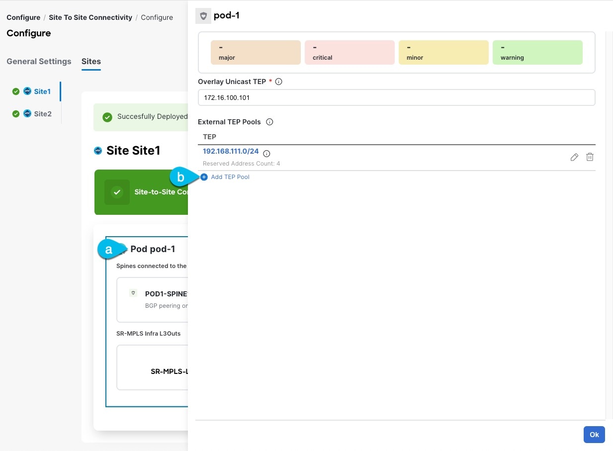
-
In the Add TEP Pool window, specify the External TEP Pool that you want to configure for that site and the Reserved Address Count.
For the TEP pool, provide the subnet and the subnet mask, for example
192.168.111.0/24.
You must ensure that the TEP pool you are adding does not overlap with any other TEP pools or fabric addresses.
Multiple disjointed TEP pools can be configured , so you are not required to specify a large TEP pool from the beginning.
-
Repeat the process for each site and pod where you plan to use intersite L3Outs.
Configuring External EPG to Use Intersite L3Out
-
Ensure that you have read and completed the requirements described in Intersite L3Out Guidelines and Limitations.
-
You must have created and deployed the L3Outs in each site as part of configuring the site’s external connectivity.
Detailed information on configuring L3Outs is available in the External Connectivity (L3Out) chapter.
This section describes how to create an external EPG that will be associated to the intersite L3Out. You can then use this external EPG and contracts to configure specific use cases for endpoints in one site to use an L3Out in another site or to configure L3Out-to-L3Out transit routing.
-
Select the schema and template where you want to create the external EPG.
If you create the external EPG in a template that is associated to multiple sites, the external EPG will be stretched across all of those sites. This is recommended when the L3Outs defined in those sites provide access to a set of common external resources, for example the WAN.
If you create the external EPG in a template that is associated with a single site, the external EPG will be created in that site only. This is recommended when the L3Out defined in that site provides access to external resources accessible only from that site.
-
Create an external EPG.
-
In the main pane, select +Create Object > External EPG.
-
Provide the Display Name for the external EPG.
For example,
eepg-intersite-l3out -
From the Virtual Routing & Forwarding dropdown, select the same VRF you associated with the L3Out.
-
-
Map the external EPG to the L3Out.
-
In the template view, select the tab for the site where the external EPG is deployed.
-
Select the external EPG you created in the previous step.
-
In the <external-epg-name> on <site-name> properties sidebar, choose the L3Out you created from the L3Out dropdown.
Note that both the APIC-managed and the Orchestrator-managed L3Outs are available for selection. You can select either the L3Out you have created and deployed from NDO or pick an L3Out that exists in the site’s APIC.
-
-
Configure one or more subnets for the external EPG.
-
Select the external EPG.
-
In the right sidebar, click +Add Subnet.
-
In the Add Subnet window’s Subnet field, provide the subnet’s network prefix.
-
(Optional) Provide a descriptive Name for the subnet.
-
Provide any required options for this subnet.
The prefixes and options you configure depend on the specific use cases:
-
To classify the inbound traffic as belonging to the external EPG, select the External Subnets for External EPG flag for the specified prefix. Depending on the specific use case, this allows you to apply a contract with an internal EPG or with the external network domain reachable via a different L3Out.
-
To advertise the external prefixes learned from another L3Out (in the same site or in a remote site) out of this L3Out, select the Export Route Control flag for the specified prefix. When specifying the
0.0.0.0/0prefix, the Aggregate Export flag can be selected to advertise all prefixes out of the L3Out; if the Aggregate Export flag is not enabled, only the default route0.0.0.0/0would be advertised, if present in the routing table of the border leaf nodes.
However, we recommend that you use the Outbound Route-Map associated to the L3Out to match the external prefixes (in addition to the BDs' subnets) to be advertised out instead.
-
To filter out specific routes received from the external network, select the Import Route Control flag for the specified prefix. If specifying the
0.0.0.0/0, you can also choose the Aggregate Import option.Note that this is possible only when peering BGP with the external routers.
However, similar to the previous bullet point, we recommend that you use the Inbound Route-Map associated to the L3Out to match the external prefixes (in addition to the BDs' subnets) to be advertised out instead.
-
To leak routes to different VRFs, select the Shared Route Control and the associated Aggregate Shared Routes flags, as well as the Shared Security Import flag. These options are required for the specific use case of inter-VRF shared L3Out and inter-VRF intersite transit routing.
-
-
-
(Optional) Enable Include in Preferred Group if you want the external EPG to be part of the EPG preferred group.
-
(Optional) From the QoS Level dropdown, select the QoS level for this external EPG.
For additional information about QoS in ACI fabrics, see Cisco APIC and QoS.
For additional information about configuring QoS Levels in your Nexus Dashboard Orchestrator, see QoS Preservation Across IPN.
Creating a Contract for Intersite L3Out
This section describes how to create a filter and a contract you will use to enable communication between an application EPG deployed in a site and the external EPG associated to an L3Out in a different site (intersite L3Out functionality).
-
Select the template where you want to create contract and filter.
You can use the same schema and template where you created the VRF and the external EPG or you can choose a different schema and template.
In earlier NDO releases, even if the contract and filters were defined only as local objects in one site (
Site1), NDO created the corresponding shadow objects in a remote site (Site2) when a local EPG or external EPG inSite2needed to consume or provide that contract.
This is no longer the case and you must define the contracts and the filters explicitly on all sites where they will be used.
-
Create a filter.
-
In the main pane, select +Create Object > Filter.
-
Provide the Display Name for the filter.
-
Click + Entry and provide the filter entry information specific to the kind of traffic you want to allow.
-
Click Ok to save the filter.
-
-
Create a contract
-
In the main pane, select +Create Object > Contract.
-
In the right pane, provide the Display Name for the contract
-
Select the appropriate Scope for the contract.
-
If both intersite L3Out and application EPG are in the same VRF, set the scope to
vrf. -
If the intersite L3Out and application EPG are in different VRFs but the VRFs are in the same tenant, set the scope to
tenant. -
If the intersite L3Out and application EPG are in different VRFs and the VRFs are in different tenants, set the scope to
global.
-
-
Ensure that the Apply both directions option is enabled if you want the same filter to apply for both consumer-to-provider and provider-to-consumer directions.
With this option enabled, you need to provide the filters only once and they will apply for traffic in both directions.
-
In the Filter Chain area, click Create Filter and choose the filter you created in the previous step.
-
Click Ok to save the contract.
-
Use Cases
Intersite L3Out for Application EPGs (Intra-VRF)
You need to have the following already configured:
-
External connectivity (L3Out) in each site, as described in the External Connectivity (L3Out) section.
In this use case, a separate L3Out will be imported or created in each site-specific template.
-
A schema with four templates.
Create a template for each site (for example,
template-site1andtemplate-site2) where you configure the objects unique to those sites, such as the application EPG and the L3Outs.In addition, create two more stretched templates: one for the stretched EPGs, External EPGs, and BDs and the second one for the VRFs, contracts, and filters.
-
The external EPG for the intersite L3Out, as described in Configuring External EPG to Use Intersite L3Out.
In this use case, the external EPG is configured as a stretched object that is defined in one of the stretched template (for example,
template-stretched-ext-epg). Assuming that the external EPG provides access to the entire external address space, we recommend configuring a0.0.0.0/0prefix for classification to avoid specifying a long list of more specific prefixes. -
The contract that you will use between the application EPG and the L3Out external EPG, as described in Creating a Contract for Intersite L3Out.
We recommend creating the contract and the filter in the second stretched template (for example,
template-stretched-vrf-contract), which also contains the VRF.
This section describes the configuration that is required to allow endpoints that are part of an application EPG to communicate with the external network domain reachable through an L3Out deployed in another site but within the same VRF (intra-VRF).
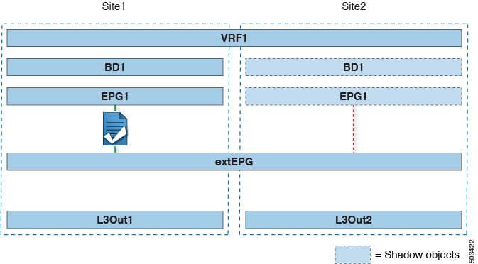
The first figure below shows a stretched external EPG and the associated L3Outs which will be created in both sites. An application EPG (EPG1) is created in Site 1 and has a contract with the external EPG. This use case is recommended when the L3Outs in the separate sites provide access to a common set of external resources. It simplifies the policy definition and external traffic classification, while still allowing you to apply route-map policies separately on each L3Out for the independent APIC domains.
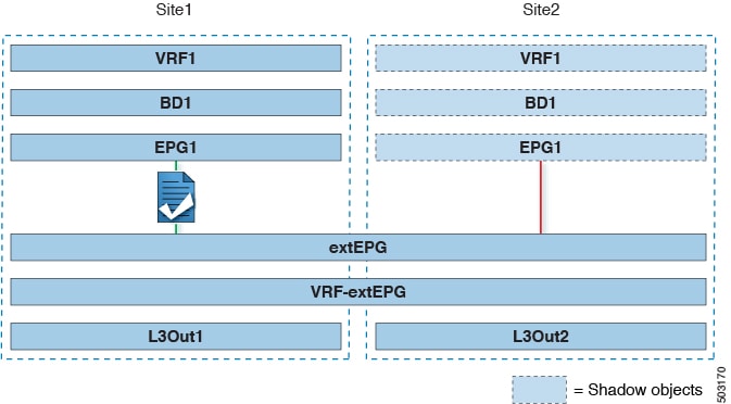
The second figure below shows a similar use case but with the external EPG being deployed to only the site where the physical L3Out is located. The application EPG and the contract are configured in the same exact way to allow the traffic flow between the EPG in one site and the physical L3Out in the other.
The following steps describe the configuration that is required to implement the use case shown in Figure 1, which represents the most common scenario. If you want to deploy the use case shown in Figure 2, you can adapt the procedure with minor changes.
-
Log in to your Cisco Nexus Dashboard Orchestrator.
-
Select the schema and template for the application EPG and bridge domain.
In this use case, you associate the template to
Site1. -
Configure an application EPG and its bridge domain belonging to the same VRF as the L3Out.
If you already have an EPG that will use the intersite L3Out, you can skip this step.
You can create a new or import an existing EPG and bridge domain as you typically would.
-
Assign the contract to the application EPG.
-
Select the EPG.
-
In the right sidebar, click +Contract.
-
Select the contract that you created in previous section and its type.
You can choose whether the application EPG is the
consumeror theprovider.
-
-
Assign the contract to the external EPG mapped to the remote L3Out.
-
Select the
template-stretchedwhere the external EPG is located. -
Select the external EPG.
-
In the right sidebar, click +Contract.
-
Select the contract that you created in previous section and its type.
If you chose the application EPG to be the
consumer, chooseproviderfor the external EPG. Otherwise, chooseconsumerfor the external EPG.
-
-
Associate the application EPG’s bridge domain with the L3Out.
This enables the BD subnet to be advertised out of the L3Out toward the external network domain. Note that one or more subnets associated to the BD must be configured with the Advertised Externally option to be advertised out of the L3Out
-
In the left sidebar, under Sites, select the application EPG’s template.
-
Select the bridge domain associated with the application EPG.
-
In the right sidebar, click +L3Out.
-
Select the intersite L3Out you created.
For the use case shown in Figure 1, associate the BD to both the L3Outs defined in Site 1 and Site 2 to ensure that the external network can have access to the EPG from both paths. Specific policies can be associated to the L3Out or to the external routers to ensure that a specific L3Out path is normally preferred for inbound traffic. We recommend this when the EPG and BD are local to a site (as in the specific example) to avoid suboptimal inbound traffic path through the remote site’s L3Out.
-
-
Deploy the schema.
Shared Services with Intersite L3Out for Application EPGs (Inter-VRF)
You must have the following already configured:
-
External connectivity (L3Out) in each site, as described in the External Connectivity (L3Out) section.
In this use case, a separate L3Out will be imported or created in each site-specific template.
-
A schema with four templates.
Create a template for each site (for example,
template-site1andtemplate-site2) where you configure the objects unique to those sites, such as the application EPG and the L3Outs.In addition, create two more stretched templates: one for the stretched External EPG and the second one for the contracts, and filters.
-
The external EPG for the intersite L3Out, as described in Configuring External EPG to Use Intersite L3Out.
In this use case, the external EPG is configured as a stretched object that is defined in the stretched template (
template-stretched). Assuming that the external EPG provides access to the entire external address space, we recommend configuring a0.0.0.0/0prefix for classification to avoid specifying a long list of more specific prefixes.For this specific shared service, use case, you are also required to enable the Shared Route Control and the Shared Security Import flags for one or more subnets that are associated to one or more external EPGs of the remote L3Out. If you are using the
0.0.0.0/0prefix for classification on the external EPG, in addition to the Shared Route Control flag, also enable the Aggregate Shared Routes flag. -
The contract that you will use between the application EPG and the L3Out external EPG, as described in Creating a Contract for Intersite L3Out.
We recommend creating the contract and the filter in the stretched template (
template-stretched).
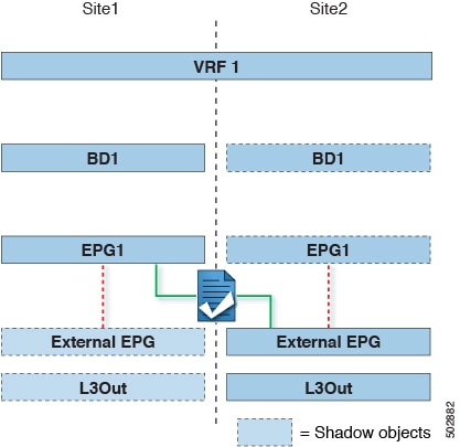
This section describes the configuration that is required to allow endpoints that are part of an application EPG in one VRF to communicate with the external network domain reachable through an L3Out deployed in another site and different VRF, this is also known as "Shared Services".
This scenario is recommended when the L3Outs in separate sites provide access to a common set of external resources. It simplifies the policy definition and external traffic classification, while still allowing you to apply route-map policies separately on each L3Out for the independent APIC domains.
The following steps describe the configuration that is required to implement the use case shown in Figure 3.
-
Log in to your Cisco Nexus Dashboard Orchestrator.
-
Select the schema and template for the application EPG and bridge domain.
In this use case, you associate the template to
Site1. -
Configure an application EPG and its bridge domain belonging to a separate VRF from the L3Out’s.
If you already have an EPG that will use the intersite L3Out, you can skip this step.
You can create a new or import an existing EPG and bridge domain as you typically would.
-
Assign the contract to the application EPG.
-
Select the EPG.
-
In the right sidebar, click +Contract.
-
Select the contract that you created in previous section and its type.
You can choose whether the application EPG is the
consumeror theprovider.
If the application EPG is configured as
provider, you must configure the subnet that is already defined under the BD also under the EPG to leak that route into the L3Out VRF. The same flags that are used under the BD for the subnet should also be set under the EPG. In addition to that, for the subnet under the EPG the flag No default SVI Gateway should also be enabled, since the default gateway function is enabled at the BD level.
-
-
Assign the contract to the external EPG mapped to the L3Outs.
-
Select the
template-stretchedwhere the external EPG is located. -
Select the external EPG.
-
In the right sidebar, click +Contract.
-
Select the contract that you created in previous section and its type.
If you chose the application EPG to be the
consumer, chooseproviderfor the external EPG. Otherwise, chooseconsumerfor the external EPG.
-
-
Associate the application EPG’s bridge domain with the L3Out.
This enables the BD subnet to be advertised out of the L3Out toward the external network domain. The subnet(s) associated to the BD must be configured with the Advertised Externally option to be advertised out of the L3Out
-
In the left sidebar, under Sites, select the application EPG’s template.
-
Select the bridge domain associated with the application EPG.
-
In the right sidebar, click +L3Out.
-
Select the intersite L3Out you created.
For the use case shown in Figure 1, associate the BD to both the L3Outs defined in Site 1 and Site 2 to ensure that the external network can have access to the EPG from both paths. Specific policies can be associated to the L3Out or to the external routers to ensure that a specific L3Out path is normally preferred for inbound traffic. We recommend this when the EPG and BD are local to a site (as in the specific example) to avoid suboptimal inbound traffic path through the remote site’s L3Out.
-
-
Deploy the schema.
Intersite Transit Routing
You must have the following already configured:
-
External connectivity (L3Out) in each site, as described in the External Connectivity (L3Out) section.
In this use case, a separate L3Out will be imported or created in each site-specific template.
-
A schema with three templates.
Create a template for each site (for example,
template-site1andtemplate-site2) where you configure the objects unique to that site, such as the application EPGs and the L3Outs. In addition, create a separate template (for example, `template-stretched `) that you use for the stretched objects, which in this case will be the external EPG. -
Two different external EPGs for two different L3Outs in different sites. You can use the same procedure to create both external EPGs, as described in Configuring External EPG to Use Intersite L3Out.
-
The contract that you use between the L3Out external EPGs defined in each site, as described in Creating a Contract for Intersite L3Out.
We recommend creating the contract and the filter in the stretched template (
template-stretched).
This section describes the use cases where the Multi-Site domain acts as a distributed router allowing communication between entities (endpoints, network devices, service nodes, and so forth) connected behind L3Outs deployed in different sites, a functionality normally saw as intersite transit routing. The intersite transit routing is supported for intra-VRF and inter-VRF use cases.
The figure below shows two L3Outs (L3Out1 and L3Out2) configured in different sites. Each L3Out is associated with a respective external EPG (External EPG1 and External EPG2). A contract between the two external EPGs allows communication between entities that are connected behind two different L3Outs in two different sites.
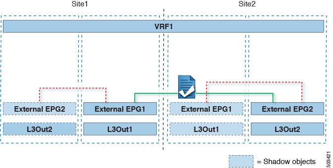
A similar configuration can be used when each site’s L3Outs are in different VRFs.
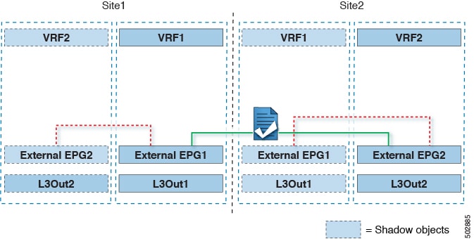
The figures above show the two scenarios where the external EPGs and associated L3Outs are deployed as site-local objects; intersite transit routing can support all the combinations where neither external EPG is stretched, one of them is stretched, or both are stretched between sites.
When deploying intersite transit routing, the assumption is that the different external EPGs defined across sites are providing access to different external address spaces (not overlapping). A couple of options are hence possible for the configuration of the prefix that is used for classification:
-
Define the
0.0.0.0/0prefix for one of the external EPGs and specific prefixes on the other.The external prefixes that are received on
L3Out1must be advertised out ofL3Out2and conversely. -
Define specific prefixes for each external EPG. In this case, you must ensure that the prefixes are not overlapping to avoid a fault from being raised by the site’s APIC when the shadow external EPG is created in that site for a contract between the local and remote external EPGs.
When using specific prefixes, the same prefixes that are configured for classification on
External EPG1must be configured with the Export Route Control flag set onExternal EPG2and conversely.
No matter which of the two classifications approaches you deploy, for the inter-VRF scenario you must also set the Shared Route Control (in addition to Aggregate Shared Routes if using 0.0.0.0/0) and the Shared Security Import flags.
-
Log in to your Cisco Nexus Dashboard Orchestrator.
-
From the left navigation pane, select Configure > Tenant Template > ApplicationsSchemas.
-
Assign the contract to one of the external EPGs.
-
Select the schema and template where the external EPG is located.
-
Select the external EPG.
-
In the right sidebar, click +Contract.
-
Select the contract that you created in previous section and its type.
Choose
consumerorprovider.
-
-
Assign the contract to the other external EPG.
-
Select the schema and template where the external EPG is located.
-
Browse to the template where the external EPG is located.
-
Select the external EPG.
-
In the right sidebar, click +Contract.
-
Select the contract that you created in previous section and its type.
Choose
providerorconsumer.
-
-
Deploy the templates to appropriate sites.
First Published: 2024-03-01
Last Modified: 2024-03-01
Americas Headquarters
Cisco Systems, Inc.
170 West Tasman Drive
San Jose, CA 95134-1706
USA
http://www.cisco.com
Tel: 408 526-4000
800 553-NETS (6387)
Fax: 408 527-0883