Cisco MDS 9000 Series IP Services Configuration Guide, Release 9.x
Bias-Free Language
The documentation set for this product strives to use bias-free language. For the purposes of this documentation set, bias-free is defined as language that does not imply discrimination based on age, disability, gender, racial identity, ethnic identity, sexual orientation, socioeconomic status, and intersectionality. Exceptions may be present in the documentation due to language that is hardcoded in the user interfaces of the product software, language used based on RFP documentation, or language that is used by a referenced third-party product. Learn more about how Cisco is using Inclusive Language.
Cisco MDS 9000 Family switches can route IP traffic between Ethernet and Fibre Channel interfaces. The IP static routing feature
is used to route traffic between VSANs. To do so, each VSAN must be in a different IP subnetwork. Each Cisco MDS 9000 Family
switch provides the following services for network management systems (NMSs):
IP forwarding on the out-of-band Ethernet interface (mgmt0) on the front panel of the supervisor modules.
IP forwarding on in-band Fibre Channel interface using the IP over Fibre Channel (IPFC) function—IPFC specifies how IP frames
can be transported over Fibre Channel using encapsulation techniques. IP frames are encapsulated into Fibre Channel frames
so NMS information can cross the Fibre Channel network without using an overlay Ethernet network.
IP routing (default routing and static routing)—If your configuration does not need an external router, you can configure
a default route using static routing.
Switches are compliant with RFC 2338 standards for Virtual Router Redundancy Protocol (VRRP) features. VRRP is a restartable
application that provides a redundant, alternate path to the gateway switch.
Note
From Cisco MDS NX-OS Release 8.3(1) and later, the VRRP feature is not supported on Cisco MDS 9000 Series Switches.
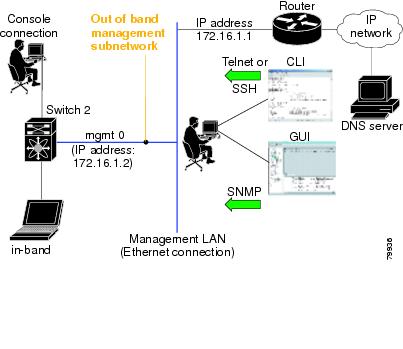
In-band options are compliant with and use the RFC 2625 standards. An NMS host running the IP protocol over an Fibre Channel
interface can access the switch using the IPFC functionality. If the NMS does not have a Fibre Channel HBA, in-band management
can still be performed using one of the switches as an access point to the fabric as shown in the following figure.
Figure 1. Management Access to Switches
Management Interface Configuration
The management interface on the switch allows multiple simultaneous Telnet or SNMP sessions. You can remotely configure the
switch through the management interface, but first you must configure IP version 4 (IPv4) parameters (IP address, subnet mask)
or an IP version 6 (IPv6) address and prefix length so that the switch is reachable. For information on configuring IPv6 addresses,
see Configuring IPv4 for Gigabit Ethernet Interfaces.
On director class switches, a single IP address is used to manage the switch. The active supervisor module's management (mgmt0)
interface uses this IP address. The mgmt0 interface on the standby supervisor module remains in an inactive state and cannot
be accessed until a switchover happens. After a switchover, the mgmt0 interface on the standby supervisor module becomes active
and assumes the same IP address as the previously active supervisor module.
Note
The port on the Ethernet switch to which the MDS management interface is connected should be configured as a host port (also
known as access port) instead of a switch port. Spanning tree configuration for that port (on the Ethernet switch) should
disabled. This helps avoid the delay in the MDS management port coming up due to delay from Ethernet spanning tree processing
that the Ethernet switch would run if enabled. For Cisco Ethernet switches, use either the switchport host command in Cisco IOS is or the set port host command in the Catalyst OS. Refer to the configuration guide for your Ethernet switch.
Note
Before you begin to configure the management interface manually, obtain the switch’s IP address and IP subnet mask. Also make
sure the console cable is connected to the console port.
This section contains the following topics:
Configuring the mgmt0 Ethernet interface for IPv4
To configure the mgmt0 Ethernet interface for IPv4, follow these steps:
Procedure
Command or Action
Purpose
Step 1
switch# config terminal
Enters configuration mode.
Step 2
switch(config)# interface mgmt0
Enters the interface configuration mode on the management Ethernet interface (mgmt0).
Step 3
switch(config-if)# ip address 10.1.1.1 255.255.255.0
Enters the IPv4 address (10.1.1.1) and IPv4 subnet mask (255.255.255.0) for the management interface.
Step 4
switch(config-if)# no shutdown
Enables the interface.
Configuring the mgmt0 Ethernet interface for IPv6
To configure the mgmt0 Ethernet interface for IPv6, follow these steps:
Procedure
Command or Action
Purpose
Step 1
switch# config terminal
Enters configuration mode.
Step 2
switch(config)# interface mgmt0
Enters the interface configuration mode on the management Ethernet interface (mgmt0).
Enters the IPv6 address (2001:0DB8:800:200C::417A) and IPv6 prefix length (/64) for the management interface and enables IPv6
processing on the interface.
Step 4
switch(config-if)# ipv6 enable
Automatically configures a link-local IPv6 address on the interface and enables IPv6 processing on the interface.
Step 5
switch(config-if)# no shutdown
Enables the interface.
Default Gateway
You can configure a default gateway IPv4 address on your Cisco MDS 9000 Family switch.
The default gateway IPv4 address should be configured along with the IPv4 static routing attributes (IP default network,
destination prefix, and destination mask, and next hop address). If you configure the static route IP forwarding and the default-network
details, these IPv4 addresses will be used regardless of the default-gateway being enabled or disabled.
The default gateway IPv4 address should be configured along with the IPv4 static routing attributes commands (IP default
network, destination prefix, and destination mask, and next hop address).
Tip
If you configure the static route IP forwarding and the default-network details, these IPv4 addresses will be used regardless
of the default-gateway being enabled or disabled. If these IP addresses are configured but not available, the switch will
fall back to using the default gateway IP address, if you have configured it. Be sure to configure IP addresses for all entries
in the switch.
Use the ip default-gateway command to configure the IP address for a switch’s default gateway and the show ip route command to verify that the IPv4 address for the default gateway is configured.
This section includes the following topics:
Configuring the Default Gateway
To configure the default gateway, follow these steps:
Procedure
Command or Action
Purpose
Step 1
switch# configure terminal
Enters configuration mode.
Step 2
switch(config)# ip default- gateway 1.12.11.1
Configures the IPv4 address for the default gateway.
Verifying the Default Gateway Configuration
Use the show ip route command to verify the default gateway configuration.
switch# show ip route
Codes: C - connected, S - static

Gateway of last resort is 1.12.11.1

S 5.5.5.0/24 via 1.1.1.1, GigabitEthernet1/1
C 1.12.11.0/24 is directly connected, mgmt0
C 1.1.1.0/24 is directly connected, GigabitEthernet1/1
C 3.3.3.0/24 is directly connected, GigabitEthernet1/6
C 3.3.3.0/24 is directly connected, GigabitEthernet1/5
S 3.3.3.0/24 via 1.1.1.1, GigabitEthernet1/1
IPv4 Default Network Configuration
If you assign the IPv4 default network address, the switch considers routes to that network as the last resort. If the IPv4
default network address is not available, the switch uses the IPv4 default gateway address. For every network configured with
the IPv4 default network address, the switch flags that route as a candidate default route, if the route is available.
If you configure the static route IP forwarding and the default network details, these IPv4 addresses will be used regardless
of the default gateway being enabled or disabled. If these IPv4 addresses are configured and not available, the switch will
fall back to using the default gateway IPv4 address, if you have configured it. Be sure to configure IPv4 addresses for all
entries in the switch if you are using IPv4.
When the Ethernet interface is configured, the switch should point to the gateway router for the IP network. The host accesses
the gateway using a gateway switch. This gateway switch is configured as the default gateway. The other switches in the fabric
that are connected to the same VSAN as the gateway switch can also be connected through the gateway switch. Every interface
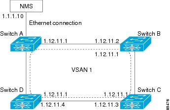
connected to this VSAN should be configured with the VSAN IPv4 address of the gateway switch as shown in the following figure.
Figure 2. Overlay VSAN Functionality
In the above figure, switch A has the IPv4 address 1.12.11.1, switch B has the IPv4 address 1.12.11.2, switch C has the IPv4
address 1.12.11.3, and switch D has the IPv4 address 1.12.11.4. Switch A is the gateway switch with the Ethernet connection.
The NMS uses the IPv4 address 1.1.1.10 to connect to the gateway switch. Frames forwarded to any switch in the overlaid VSAN
1 are routed through the gateway switch. Configuring the gateway switch’s IPv4 address (1.12.11.1) in the other switches enable
the gateway switch to forward the frame to the intended destination. Similarly, if a non-gateway switch in the VSAN forwards
a frame to the Ethernet, the frame is routed through the gateway switch.
When forwarding is disabled (default), IP frames are not sent from one interface to another. In these cases, the software
performs local IP routing between two switches using the in-band option for Fibre Channel traffic and the mgmt0 option for
Ethernet traffic.
When a VSAN is created, a VSAN interface is not created automatically. You need to specifically create the interface.
To configure default networks using IPv4 addresses, follow these steps:
Procedure
Command or Action
Purpose
Step 1
switch# configure terminal
Enters configuration mode.
Step 2
switch(config)# ip default- network 190.10.1.0
Configures the IPv4 address for the default network (190.10.1.0).
Step 3
switch(config)# ip route 10.0.0.0 255.0.0.0 131.108.3.4
Defines the ip route to network.
Step 4
switch(config)# ip default-network 10.0.0.0
Defines a static route to network 10.0.0.0 as the static default route.
IP over Fibre Channel
IP over Fibre Channel (IPFC) provides IP forwarding on in-band switch management over a Fibre Channel interface (rather than
out-of-band using the Gigabit Ethernet mgmt 0 interface). You can be use IPFC to specify that IP frames can be transported
over Fibre Channel using encapsulation techniques. IP frames are encapsulated into Fibre Channel frames so NMS information
can cross the Fibre Channel network without using an overlay Ethernet network.
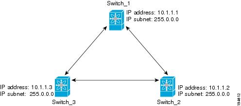
Once the VSAN interface is created, you can specify the IP address for that VSAN. You can assign an IPv4 address or an IPv6
address.
switch_3(config-if)# ip address 10.1.1.3 255.0.0.0
Enable the VSAN interface and exit interface configuration submode:
switch_3(config-if)# no shutdown
switch_3(config-if)# exit
switch_3(config)#
Enable IPv4 routing:
switch_3(config)# ip routing
switch_3(config)# exit
switch_3#
Display the routes:
switch_3# show ip route

Codes: C - connected, S - static

C 10.0.0.0./8 is directly connected, vsan1
Verify the connectivity to Switch_1:
switch_3# ping 10.1.1.1
PING 10.1.1.1 (10.1.1.1) 56(84) bytes of data.
64 bytes from 10.1.1.1: icmp_seq=1 ttl=64 time=1.19 ms
64 bytes from 10.1.1.1: icmp_seq=2 ttl=64 time=0.510 ms
64 bytes from 10.1.1.1: icmp_seq=3 ttl=64 time=0.653 ms

--- 10.1.1.1 ping statistics ---
3 packets transmitted, 3 received, 0% packet loss, time 2008 ms
rtt min/avg/max/mdev = 0.510/0.787/1.199/0.297 ms
IPv4 Static Routes
Static routing is a mechanism to configure IPv4 routes on the switch. You can configure more than one static route.
If a VSAN has multiple exit points, configure static routes to direct traffic to the appropriate gateway switch. IPv4 routing
is disabled by default on any gateway switch between the out-of-band management interface and the default VSAN, or between
directly connected VSANs.
If your network configuration does not need an external router, you can configure IPv4 static routing on your MDS switch.
Use the show ip route command to verifying the active and connected IPv4 static route:
switch# show ip route

Codes: C - connected, S - static

Default gateway is 172.22.95.1

C 172.22.95.0/24 is directly connected, mgmt0
C 10.1.1.0/24 is directly connected, vsan1
Displaying the IP Routing Status
switch# show ip routing
ip routing is disabled
Displaying and Clearing ARPs
Address Resolution Protocol (ARP) entries in Cisco MDS 9000 Family switches can be displayed, deleted, or cleared. The ARP
feature is enabled on all switches.
Use the show arp command to display the ARP table.
switch# show arp
Protocol Address Age (min) Hardware Addr Type Interface
Internet 171.1.1.1 0 0006.5bec.699c ARPA mgmt0
Internet 172.2.0.1 4 0000.0c07.ac01 ARPA mgmt0
Use the no arp command in configuration mode to remove an ARP entry from the ARP table.
switch(config)# no arp 172.2.0.1
Use the clear arp command to delete all entries from the ARP table. The ARP table is empty by default:
switch# clear arp-cache
Overlay VSANs
VSANs enable deployment of larger SANs by overlaying multiple logical SANs, each running its own instance of fabric services,
on a single large physical network. This partitioning of fabric services reduces network instability by containing fabric
reconfiguration and error conditions within an individual VSAN. VSANs also provide the same isolation between individual VSANs
as physically separated SANs. Traffic cannot cross VSAN boundaries and devices may not reside in more than one VSAN. Because
each VSAN runs separate instances of fabric services, each VSAN has its own zone server and can be zoned in exactly the same
way as SANs without VSAN capability.
This section includes the following topics:
Configuring Overlay VSANs
To configure an overlay VSAN, follow these steps:
Add the VSAN to the VSAN database on all switches in the fabric.
Create a VSAN interface for the VSAN on all switches in the fabric. Any VSAN interface belonging to the VSAN has an IP address
in the same subnet. Create a route to the IPFC cloud on the IP side.
Configure a default route on every switch in the Fibre Channel fabric pointing to the switch that provides NMS access.
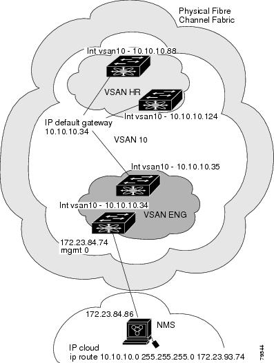
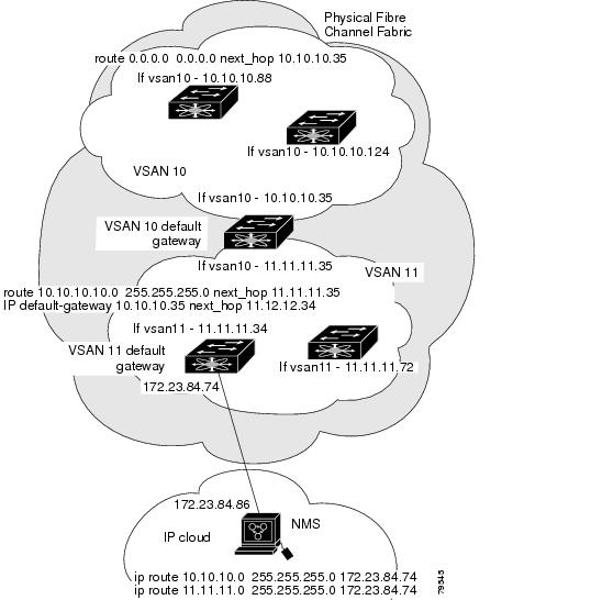
Configure the default gateway (route) and the IPv4 address on switches that point to the NMS as shown in the following figure.
Figure 4. Overlay VSAN Configuration Example
Note
To configure the management interface displayed in above figure, set the default gateway to an IPv4 address on the Ethernet
network.
The following procedure configures an overlay VSAN in one switch. This procedure must be repeated for each switch in the fabric.
To configure an overlay VSAN in one switch (using the example in the above figure), follow these steps:
Procedure
Command or Action
Purpose
Step 1
switch# config terminal
Enters configuration mode.
Step 2
switch(config)# vsan database
Configures the VSAN database.
Step 3
switch--config-vsan-db# vsan 10 name MGMT_VSAN
Defines the VSAN in the VSAN database on all of the switches in the Fibre Channel fabric.
Step 4
switch--config-vsan-db# exit
Exits the VSAN database mode.
Step 5
switch(config)# interface vsan 10
Creates a VSAN interface (VSAN 10).
Step 6
switch(config-if)# ip address 10.10.10.0 netmask 255.255.255.0
Assigns an IPv4 address and subnet mask for this switch.
Step 7
switch(config-if)# no shutdown
Enables the configured interface.
Step 8
switch(config-if)# end
Exits to EXEC mode.
Step 9
switch# exit
Exits the switch and returns to the NMS. In this example the NMS is assumed to be on the same subnet of the Ethernet management
interface of the edge that provides access to the Fibre Channel fabric.
What to do next
To configure the NMS station displayed in the above figure, use the following command:
Defines a static route on the NMS pointing to the management interface of the edge switch that provides access to the Fibre
Channel fabric.
Configuring Multiple VSANs
More than one VSAN can be used to segment the management network in multiple subnets. An active interface must be present
on the switch for the VSAN interface to be enabled.
To configure multiple VSANs, follow these steps:
Add the VSAN to the VSAN database on any switch in the fabric.
Create a VSAN interface for the appropriate VSAN on any switch in the fabric.
Assign an IP address on every VSAN interface on the same subnet as the corresponding VSAN.
Define the multiple static routes on the Fibre Channel switches and the IP cloud as shown in the following figure.
Figure 5. Multiple VSAN Configuration Example
To configure an overlay VSAN (using the example in the previous figure), follow these steps:
Procedure
Command or Action
Purpose
Step 1
switch# config terminal
Enters configuration mode.
Step 2
switch(config)# vsan database
Configures the VSAN database.
Step 3
switch-config-vsan-db# vsan 10 name MGMT_VSAN_10
Defines the VSAN in the VSAN database on all of the switches in VSAN 10.
Step 4
witch-config-vsan-db# exit
Exits the VSAN database configuration submode.
Step 5
switch-config-vsan-db# vsan 11 name MGMT_VSAN_11
Defines the VSAN in the VSAN database on all of the switches in VSAN 11.
Step 6
switch-config-vsan-db# exit
Exits the VSAN database configuration submode.
Step 7
switch(config)# interface vsan 10
Enters the interface configuration submode for VSAN 10.
Step 8
switch(config-if)# ip address 10.10.10.0 netmask 255.255.255.0
Assigns an IPv4 address and subnet mask for this interface.
Step 9
switch(config-if)# no shutdown
Enables the configured interface for VSAN 10.
Step 10
switch(config-if)# exit
Exits the VSAN 10 interface mode.
Step 11
switch(config)# interface vsan 11
Enters the interface configuration submode for VSAN 11.
Step 12
switch(config-if)# ip address 11.11.11.0 netmask 255.255.255.0
Assigns an IPv4 address and subnet mask for this interface.
Step 13
switch(config-if)# no shutdown
Enables the configured interface for VSAN 11.
Step 14
switch(config-if)# end
Exits to EXEC mode.
Step 15
switch# exit
Exits the switch and returns to the NMS. In this example the NMS is assumed to be on the same subnet of the Ethernet management
interface of the edge that provides access to the Fibre Channel fabric.
Defines a static route for VSAN 11 on the NMS pointing to the management interface of the edge switch that provides access
to the Fibre Channel fabric.
Defines the route to reach subnet 10 from subnet 11.
DNS Configuration
The DNS client on the switch communicates with the DNS server to perform the IP address-name server correspondence.
The DNS server may be dropped after two attempts because of one of the following reasons:
The IP address or the switch name is wrongly configured.
The DNS server is not reachable because external reasons (reasons beyond our control).
Note
When accessing a Telnet host, if the DNS server is not reachable (for any reason) the switch login prompt may take a longer
time to appear. If so, verify that the DNS server is accurately configured and reachable.
To configure a DNS server, follow these steps:
Procedure
Command or Action
Purpose
Step 1
switch# config terminal
Enters configuration mode.
Step 2
switch(config)# ip domain-lookup
Enables the IP Domain Naming System (DNS)-based host name-to-address translation.
Step 3
switch(config)# no ip domain-lookup
Disables (default) the IP DNS-based host name-to-address translation and reverts to the factory default.
Step 4
switch(config)# ip domain-name cisco.com
Enables the default domain name feature used to complete unqualified host names. Any IP host name that does not contain a
domain name (that is, any name without a dot) will have the dot and cisco.com appended to it before being added to the host
table.
Step 5
switch(config)# no ip domain-name cisco.com
Disables (default) the domain name.
Step 6
switch(config)# ip domain-list harvard.edu or switch(config)# ip domain-list stanford.edu or switch(config)# ip domain-list yale.edu
Defines a filter of default domain names to complete unqualified host names by using the ip domain-list global configuration
command. You can define up to 10 domain names in this filter. To delete a name from a filter, use the no form of this command.
Note
If you have not configured a domain list, the domain name that you specified with the ip domain-name global configuration
command is used. If you configured a domain list, the default domain name is not used. The ip domain-list command is similar
to the ip domain-name command, except that with the ip domain-list command you can define a list of domains, each to be tried
in turn.
Step 7
switch(config)# no ip domain-list
Deletes the defined filter and reverts to factory default. No domains are configured by default.
Step 8
switch(config)# ip name-server 15.1.0.1 2001:0db8:800:200c::417a
Specifies the first address (15.1.0.1) as the primary server and the second address (2001:0db8:800:200c::417a) as the secondary
server. You can configure a maximum of six servers.
Note
Alternatively, you can configure the DNS entry using the switch names (instead of IP addresses). The configured switch name
automatically looks up the corresponding IP address.
Step 9
switch(config)# no ip name-server
Deletes the configured server(s) and reverts to factory default. No server is configured by default.
Displaying DNS Host Information
Use the show hosts command to display the DNS configuration.
Displaying Configured Host Details
switch# show hosts
Default domain is cisco.com
Domain list: ucsc.edu harvard.edu yale.edu stanford.edu
Name/address lookup uses domain service
Default Settings for DNS Features
The below table lists the default settings for DNS features.


 Feedback