Configuring the SAN Extension Tuner

The SAN Extension Tuner (SET) feature is unique to the Cisco MDS 9000 Family of switches. This feature helps you optimize FCIP performance by generating either direct access (magnetic disk) or sequential access (magnetic tape) SCSI I/O commands and directing such traffic to a specific virtual target. You can specify the size of the test I/O transfers and how many concurrent or serial I/Os to generate while testing. The SET reports the resulting I/Os per second (IOPS) and I/O latency, which helps you determine the number of concurrent I/Os needed to maximize FCIP throughput.

This chapter includes the following sections:

Overview of SAN Extension Tuner

The SAN extension tuner (SET) feature is unique to the Cisco MDS 9000 Family of switches. This feature helps you optimize FCIP performance by generating either direct access (magnetic disk) or sequential access (magnetic tape) SCSI I/O commands and directing such traffic to a specific virtual target. Applications such as remote copy and data backup use FCIP over an IP network to connect across geographically distributed SANs. SET is implemented in IPS ports. When enabled, this feature can be used to generate SCSI I/O commands (read and write) to the virtual target based on your configured options.


Note


SAN Extension Tuner is not supported on the Cisco Fabric Switch for HP c-Class BladeSystem, the Cisco Fabric Switch for IBM BladeCenter, and 16-Port Storage Services Node (SSN-16).


Note


As of Cisco MDS SAN-OS Release 3.3(1a), SAN Extension Tuner is supported on the Multiservice Module (MSM) and the Multiservice Modular Switch.


Applications such as remote copy and data backup use FCIP over an IP network to connect across geographically distributed SANs. To achieve maximum throughput performance across the fabric, you can tune the following configuration parameters:

  • The TCP parameters for the FCIP profile (see Window Management for more information).

  • The number of concurrent SCSI I/Os generated by the application.

  • The transfer size used by the application over an FCIP link.

SET is implemented in IPS ports. When enabled, this feature can be used to generate SCSI I/O commands (read and write) to the virtual target based on your configured options (see the following figure).

Figure 1. SCSI Command Generation to the Virtual Target

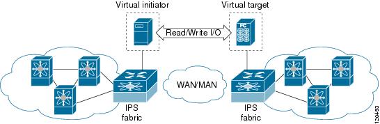
The SET feature assists with tuning by generating varying SCSI traffic workloads. It also measures throughput and response time per I/ O over an FCIP link.

Before tuning the SAN fabric, be aware of the following guidelines:

  • Following these implementation details:

    • The tuned configuration is not persistent.

    • The virtual N ports created do not register FC4 features supported with the name server. This is to avoid the hosts in the SAN from discovering these N ports as regular initiators or targets.

    • Login requests from other initiators in the SAN are rejected.

    • The virtual N ports do not implement the entire SCSI suite; it only implements the SCSI read and write commands.

    • Tuner initiators can only communicate with tuner targets.

  • Verify that the Gigabit Ethernet interface is up at the physical layer (GBIC and Cable connected—an IP address is not required).

  • Enable iSCSI on the switch (no other iSCSI configuration is required).

  • Enable the interface (no other iSCSI interface configuration is required)

  • Create an iSCSI interface on the Gigabit Ethernet interface and enable the interface (no other iSCSI interface configuration is required)

    See Creating iSCSI Interfaces for more information.

  • Configure the virtual N ports in a separate VSAN or zone as required by your network.

  • Be aware that a separate VSAN with only virtual N ports is not required, but is recommended as some legacy HBAs may fail if logins to targets are rejected.

  • Do not use same Gigabit Ethernet interface to configure virtual N ports and FCIP links—use different Gigabit Ethernet interfaces. While this is not a requirement, it is recommended as the traffic generated by the virtual N ports may interfere with the performance of the FCIP link.

SAN Extension Tuner Setup

The below figure provides a sample physical setup in which the virtual N ports are created on ports that are not a part of the FCIP link for which the throughput and latency is measured.

Figure 2. Port Tuning Configuration Physical Example

The below figure provides a sample logical setup in which the virtual N ports are created on ports that are not a part of the FCIP link for which the throughput and latency is measured.

Figure 3. Logical Example of N Port Tuning for an FCIP Link

Data Pattern

By default, an all-zero pattern is used as the pattern for data generated by the virtual N ports. You can optionally specify a file as the data pattern to be generated by selecting a data pattern file from one of three locations: the bootflash: directory, the volatile: directory, or the slot0: directory. This option is especially useful when testing compression over FCIP links. You can also use Canterbury corpus or artificial corpus files for benchmarking purposes.

License Prerequisites

To use the SET, you need to obtain the SAN_EXTN_OVER_IP license (see the Cisco Family NX-OS Licensing Guide).

Configuring the SAN Extension Tuner

This section includes the following topics:

Tuning the FCIP Link

To tune the required FCIP link, follow these steps:

Procedure


Step 1

Configure the nWWN for the virtual N ports on the switch.

Step 2

Enable iSCSI on the interfaces on which you want to create the N ports.

Step 3

Configure the virtual N ports on either side of the FCIP link.

Step 4

Ensure that the virtual N ports are not visible to real initiators in the SAN. You can use zoning (see the Cisco MDS 9000 Family NX-OS Fabric Configuration Guide) to segregate the real initiators.

Ensure that the zoning configuration is set up to allow the virtual N ports to communicate with each other.

Step 5

Start the SCSI read and write I/Os.

Step 6

Add more N ports (as required) to other Gigabit Ethernet ports in the switch to obtain maximum throughput. One scenario that may require additional N ports is if you use FCIP PortChannels.


Enabling the Tuner

The tuning feature is disabled by default in all switches in the Cisco 9000 Family. When you enable this feature, tuning is globally enabled for the entire switch.

To enable the tuning feature, follow these steps:

Procedure

  Command or Action Purpose

Step 1

switch# configure terminal

Enters configuration mode.

Step 2

switch(config)# feature san-ext-tuner

Enables tuning.

Step 3

switch(config)# no feature san-ext-tuner

Removes the currently applied tuning configuration and disables tuning (default).

Configuring nWWN

To configure the nWWNs for the tuner in this switch, follow these steps:

Procedure

  Command or Action Purpose

Step 1

switch# san-ext-tuner

Enters the SET configuration submode.

Step 2

switch(san-ext)# nWWN 10:00:00:00:00:00:00:00

Configures the nWWN for the SAN extension tuner.

Configuring the Virtual N Port

To configure the virtual N port for tuning, follow these steps:

Procedure

  Command or Action Purpose

Step 1

switch# configure terminal

Enters configuration mode.

Step 2

switch(config)# feature iscsi

Enables iSCSI globally.

Step 3

switch(config)# iscsi enable module 1

Enables iSCSI on module 1.

Step 4

switch(config)# interface iscsi 1/1

Creates an iSCSI interface and enters interface configuration submode.

Step 5

switch(config-if)# no shutdown

Enables the iSCSI interface.

Step 6

switch(config-if)# end

Returns to EXEC mode.

Step 7

switch# san-ext-tuner

Enters the SET configuration submode.

Step 8

switch(san-ext)# nport pWWN 12:00:00:00:00:00:00:56 vsan 200 interface gigabitethernet 1/1

Creates a virtual N port on the specified Gigabit Ethernet port and VSAN. This N port can act as an initiator or a target.

Step 9

(Optional) switch(san-ext)# no nport pWWN 22:34:56:78:90:12:34:56 vsan 200 interface gigabitethernet 1/1

(Optional)

Removes a virtual N port on the specified Gigabit Ethernet port and VSAN.

Generating SCSI Disk Read/Write IO

You can assign SCSI read and write commands on a one-time basis or on a continuous basis.

This section includes the following topics:

Generating SCSI Disk Read/Write IO One Time

To generate SCSI read or write commands on a one-time basis, follow these steps:

Procedure
  Command or Action Purpose

Step 1

switch# san-ext-tuner

Enters the SET configuration submode.

Step 2

switch(san-ext)# nport pWWN 12:00:00:00:00:00:00:56 vsan 200 interface gigabitethernet 1/1

Creates a virtual N port on the specified Gigabit Ethernet port and VSAN. This N port can act as an initiator or a target.

Step 3

switch(san-ext-nport)# read command-id 100 target 22:22:22:22:22:22:22:22 transfer-size 512000 outstanding-ios 2 num-transactions 5000000

Specifies a transfer size of 512,000 bytes with two outstanding I/Os in the read command. The total number of I/Os is 5,000,000 bytes.

Step 4

switch(san-ext-nport)# write command-id 101 target 22:22:22:22:22:22:22:22 transfer-size 512000 outstanding-ios 2 num-transactions 5000000

Specifies a transfer size of 512,000 bytes with two outstanding I/Os in the write command received by the target. The total number of I/Os is 5,000,000 bytes.

Step 5

switch(san-ext-nport)# stop command-id 100

Stops the command with the specified ID.

Step 6

(Optional) switch(san-ext-nport)# stop all

(Optional)

Stops all outstanding commands.

Step 7

switch(san-ext-nport)# clear counters

Clears the counters associated with this N port.

Step 8

switch(san-ext-nport)# end

Exits the SAN extension tuner submode.

Generating SCSI Disk Read/Write IO Continuously

To generate SCSI read or write commands continuously, follow these steps:

Procedure
  Command or Action Purpose

Step 1

switch# san-ext-tuner

Enters the SET configuration submode.

Step 2

switch(san-ext)# nport pWWN 12:00:00:00:00:00:00:56 vsan 200 interface gigabitethernet 1/1

Creates a virtual N port on the specified Gigabit Ethernet port and VSAN. This N port can act as an initiator or a target.

Step 3

switch(san-ext-nport)# read command-id 100 target 22:22:22:22:22:22:22:22 transfer-size 512000 outstanding-ios 2 continuous

Configures SCSI commands to be read continuously.

Tip


Use the stop command-id command to stop the outstanding configuration.

Step 4

switch(san-ext-nport)# write command-id 100 target 22:22:22:22:22:22:22:22 transfer-size 512000 outstanding-ios 2 continuous

Configures SCSI commands to be written continuously.

Step 5

switch(san-ext-nport)# stop command-id 100

Stops the command with the specified ID.

Step 6

(Optional) switch(san-ext-nport)# stop command-id all

(Optional)

Stops all outstanding commands.

Step 7

(Optional) switch(san-ext-nport)# stop all

(Optional)

Stops all outstanding commands.

Step 8

switch(san-ext-nport)# clear counters

Clears the counters associated with this N port.

Step 9

switch(san-ext-nport)# end

Exits the SAN extension tuner submode.

Transferring Ready Size for SCSI

To specify a transfer ready size for a SCSI write command, follow these steps:

Procedure
  Command or Action Purpose

Step 1

switch# san-ext-tuner

Enters the SET configuration submode.

Step 2

switch(san-ext)# nport pWWN 12:00:00:00:00:00:00:56 vsan 200 interface gigabitethernet 1/1

Creates a virtual N port on the specified Gigabit Ethernet port and VSAN. This N port can act as an initiator or a target.

Step 3

switch(san-ext-nport)# write command-id 100 target 22:22:22:22:22:22:22:22 transfer-size 512000 outstanding-ios 2 num-transactions 5000000

Specifies a transfer size of 512,000 bytes with two outstanding I/Os in the write command received by the target. The total number of I/Os is 5,000,000 bytes.

Step 4

switch(san-ext-nport)# transfer-ready-size 512000

Specifies the maximum transfer ready size of 512,000 bytes as a target for SCSI write commands. For a SCSI write command with a larger size, the target performs multiple transfers based on the specified transfer size.

Step 5

switch(san-ext-nport)# no transfer-ready-size 512000

Removes the specified transfer ready size configuration for SCSI write commands.

Step 6

switch(san-ext-nport)# stop command-id 100

Stops the command with the specified ID.

Step 7

switch(san-ext-nport)# end

Exits the SAN extension tuner submode.

Generating SCSI Tape Read/Write IO

You can assign SCSI tape read and write commands on a one-time basis or on a continuous basis.


Note


  • Ensure that the zoning configuration is set up to allow the virtual N-ports to communicate with each other.

  • There is only one outstanding I/O at a time to the virtual N-port that emulates the tape behavior.


This section contains the following topics:

Generating SCSI Tape Read/Write IO One Time

To generate SCSI tape read and or write commands on a one-time basis, follow these steps:

Procedure
  Command or Action Purpose

Step 1

switch# san-ext-tuner

Enters the SET configuration submode.

Step 2

switch(san-ext)# nport pWWN 12:00:00:00:00:00:00:56 vsan 200 interface gigabitethernet 1/1

Creates a virtual N port on the specified Gigabit Ethernet port and VSAN. This N port can act as an initiator or a target.

Step 3

switch(san-ext-nport)# tape-read command-id 100 target 22:22:22:22:22:22:22:22 transfer-size 512000 num-transactions 5000000 filemark-frequency 32

Specifies a transfer size of 512,000 bytes with space over the filemark every 32 SCSI read commands. The total number of I/Os is 5,000,000 bytes.

Step 4

switch(san-ext-nport)# tape-write command-id 101 target 22:22:22:22:22:22:22:22 transfer-size 512000 num-transactions 5000000 filemark-frequency 32

Specifies a transfer size of 512,000 bytes with filemarks written every 32 SCSI write commands. The total number of I/Os is 5,000,000 bytes.

Step 5

switch(san-ext-nport)# stop command-id 100

Stops the command with the specified ID.

Step 6

(Optional) switch(san-ext-nport)# stop all

(Optional)

Stops all outstanding commands.

Step 7

switch(san-ext-nport)# clear counters

Clears the counters associated with this N port.

Step 8

switch(san-ext-nport)# end

Exits the SAN extension tuner submode.

Generating SCSI Tape Read/Write IO Continuously

To generate SCSI tape read or write commands continuously, follow these steps:

Procedure
  Command or Action Purpose

Step 1

switch# san-ext-tuner

Enters the SET configuration submode.

Step 2

switch(san-ext)# nport pWWN 12:00:00:00:00:00:00:56 vsan 200 interface gigabitethernet 1/1

Creates a virtual N port on the specified Gigabit Ethernet port and VSAN. This N port can act as an initiator or a target.

Step 3

switch(san-ext-nport)# tape-read command-id 100 target 22:22:22:22:22:22:22:22 transfer-size 512000 continuous filemark-frequency 32

Configures SCSI tape read commands to be issued continuously.

Tip


Use the stop command-id command to stop the outstanding configuration.

Step 4

switch(san-ext-nport)# tape-write command-id 100 target 22:22:22:22:22:22:22:22 transfer-size 512000 continuous filemark-frequency 32

Configures SCSI tape write commands to be issued continuously.

Step 5

switch(san-ext-nport)# stop command-id 100

Stops the command with the specified ID.

Step 6

(Optional) switch(san-ext-nport)# stop command-id all

(Optional)

Stops all outstanding commands.

Step 7

switch(san-ext-nport)# clear counters

Clears the counters associated with this N port.

Step 8

switch(san-ext-nport)# end

Exits the SAN extension tuner submode.

Transferring Ready Size for SCSI

To specify a transfer ready size for a SCSI write command, follow these steps:

Procedure
  Command or Action Purpose

Step 1

switch# san-ext-tuner

Enters the SET configuration submode.

Step 2

switch(san-ext)# nport pWWN 12:00:00:00:00:00:00:56 vsan 200 interface gigabitethernet 1/1

Creates a virtual N port on the specified Gigabit Ethernet port and VSAN. This N port can act as an initiator or a target.

Step 3

switch(san-ext-nport)# write command-id 100 target 22:22:22:22:22:22:22:22 transfer-size 512000 outstanding-ios 2 num-transactions 5000000

Specifies a transfer size of 512,000 bytes with two outstanding I/Os in the write command received by the target. The total number of I/Os is 5,000,000 bytes.

Step 4

switch(san-ext-nport)# transfer-ready-size 512000

Specifies the maximum transfer ready size of 512,000 bytes as a target for SCSI write commands. For a SCSI write command with a larger size, the target performs multiple transfers based on the specified transfer size.

Step 5

switch(san-ext-nport)# no transfer-ready-size 512000

Removes the specified transfer ready size configuration for SCSI write commands.

Step 6

switch(san-ext-nport)# stop command-id 100

Stops the command with the specified ID.

Step 7

switch(san-ext-nport)# end

Exits the SAN extension tuner submode.

Configuring a Data Pattern

To optionally configure a data pattern for SCSI commands, follow these steps:

Procedure

  Command or Action Purpose

Step 1

switch# san-ext-tuner

Enters the SET configuration submode.

Step 2

switch(san-ext)# nport pWWN 12:00:00:00:00:00:00:56 vsan 200 interface gigabitethernet 1/1

Creates a virtual N port on the specified Gigabit Ethernet port and VSAN. This N port can act as an initiator or a target.

Step 3

switch(san-ext-nport)# data-pattern-file bootflash://DataPatternFile

Specifies the data pattern sent by the virtual N port when it is a target for read commands and an initiator for write commands.

Tip


This command should be configured on the target to change the data returned by read commands and on the initiator for write commands. This command is useful to define data sets which contain certain bit patterns or have certain compression ratios. The default data set of all zeros is very homogenous and very compressible.

Step 4

(Optional) switch(san-ext-nport)# no data-pattern-file

(Optional)

Removes the specified data pattern configuration for SCSI read and write commands. The default is to send an all zero data pattern.

Step 5

switch(san-ext-nport)# write command-id 100 target 22:22:22:22:22:22:22:22 transfer-size 512000 outstanding-ios 2 num-transactions 5000000

Specifies a transfer size of 512,000 bytes with two outstanding I/Os. The total number of I/Os is 5,000,000 bytes.

Step 6

switch(san-ext-nport)# stop command-id 100

Stops the command with the specified ID.

Step 7

switch(san-ext-nport)# clear counters

Clears the counters associated with this N port.

Step 8

switch(san-ext-nport)# end

Exits the SAN extension tuner submode.

Verifying the SAN Extension Tuner Configuration

The show commands display the current SAN extension tuner settings for the Cisco MDS switch.

Displaying Entries in the FLOGI Database

switch# show flogi database
------------------------------------------------------------------------------
INTERFACE VSAN FCID     PORT NAME               NODE NAME 
------------------------------------------------------------------------------
iscsi1/1   200 0x050000 12:00:00:00:00:00:00:56 10:00:00:00:00:00:00:00 

Displaying Details for a VSAN Entry in the FLOGI Database

switch# show fcns database vsan 200
VSAN 200
--------------------------------------------------------------------------
FCID TYPE PWWN (VENDOR) FC4-TYPE:FEATURE
--------------------------------------------------------------------------
0x020000 N 22:22:22:22:22:22:22:22 scsi-fcp
0x050000 N 12:00:00:00:00:00:00:56 scsi-fcp

Displaying All Virtual N Ports Configured on the Specified Interface

switch# show san-ext-tuner interface gigabitethernet 3/4 nport pWWN 12:00:00:00:00:00:00:56 vsan 200 counters
Statistics for nport
Node name 10:00:00:00:00:00:00:00 Port name 12:00:00:00:00:00:00:56
I/Os per second : 148
Read : 0%
Write : 100%
Ingress MB per second : 0.02 MBs/sec (Max -0.02 MBs/sec)
Egress MB per second : 73.97 MBs/sec (Max -75.47 MBs/sec))
Average Response time per I/O : Read - 0 us, Write - 13432 us
Maximum Response time per I/O : Read - 0 us, Write - 6953 us
Minimum Response time per I/O : Read - 0 us, Write - 19752 us
Errors : 0

Displaying N Ports Configured on a Specified Gigabit Ethernet Interface

switch# show san-ext-tuner interface gigabitethernet 3/1
----------------------------------------------------------------------------
Interface          NODE NAME               PORT                    NAME VSAN
----------------------------------------------------------------------------
GigabitEthernet3/1 10:00:00:00:00:00:00:00 10:00:00:00:00:00:00:01 91

Displaying the Transfer Ready Size Configured for a Specified N Port

switch# show san-ext-tuner interface gigabitethernet 3/1 nport pWWN 10:0:0:0:0:0:0:1 vsan 91
Node name : 10:00:00:00:00:00:00:00
Port name : 10:00:00:00:00:00:00:01
Transfer ready size : all

Displaying All Virtual N Ports Configured in a Switch

switch# show san-ext-tuner nports
----------------------------------------------------------------------------
Interface          NODE NAME               PORT NAME               VSAN
----------------------------------------------------------------------------
GigabitEthernet3/1 10:00:00:00:00:00:00:00 10:00:00:00:00:00:00:01 91

Default Settings for Tuning Parameters

The following table lists the default settings for tuning parameters.

Table 1. Default Tuning Parameters
Parameters Default
Tuning Disabled
Transfer ready size Same as the transfer size in the SCSI write command
Outstanding I/Os 1
Number of transactions 1
Data generation format All-zero format
File mark frequency 0