Fabric Initialization and Switch Discovery

This chapter contains these sections:

Fabric initialization

When you initialize the fabric, you add switches to be managed by the APIC and you validate the steps using the GUI, CLI, or API. Before you start this process, you must create an APIC cluster over the out-of-band network.

Fabric Topology

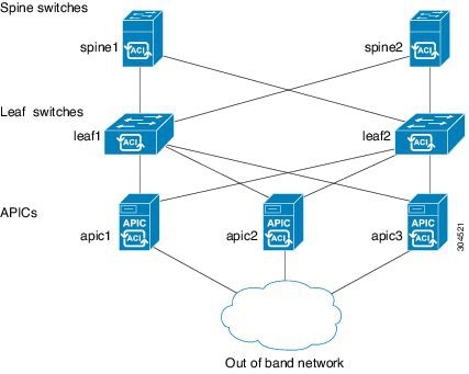
An example of a fabric topology includes:

  • Two spine switches (spine1, spine2)

  • Two leaf switches (leaf1, leaf2)

  • Three instances of APIC (apic1, apic2, apic3)

The figure shows an example of a fabric topology.

Figure 1. Fabric Topology Example


Connections: fabric topology

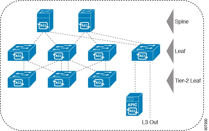
An example of a fabric topology is as follows:

  • Two spine switches (spine1, spine2)

  • Two leaf switches (leaf1, leaf2)

  • Three instances of APIC (apic1, apic2, apic3)

The following figure shows an example of a fabric topology.

Figure 2. Fabric Topology Example


Multi-tier fabric topologies example

A multi-tier fabric topology is a data center network design that uses an additional layer of leaf switches, creating a three-tier structure. This design is intended for large data center deployments where it separates aggregation and access network functions onto distinct switch layers, enabling flexible connectivity and port usage through configurable fabric ports.

3-tier Core-Aggregation-Access architectures are common in data center network topologies. As of the Cisco APIC 4.1(1) release, you can create a multi-tier ACI fabric topology that corresponds to the Core-Aggregation-Access architecture, mitigating the need to upgrade costly components such as rack space or cabling. The addition of a tier-2 leaf layer makes this topology possible. The tier-2 leaf layer supports connectivity to hosts or servers on the downlink ports and connectivity to the leaf layer (aggregation) on the uplink ports.

In the multi-tier topology, the leaf switches initially have uplink connectivity to the spine switches and downlink connectivity to the tier-2 leaf switches. To make the entire topology an ACI fabric, all ports on the leaf switches connecting to tier-2 leaf fabric ports must be configured as fabric ports (if not already using the default fabric ports). After APIC discovers the tier-2 leaf switch, you can change the downlink port on the tier-2 leaf to a fabric port and connect to an uplink port on the middle layer leaf.


Note


If you are not using the default fabric ports to connect leaf switches to tier-2 leaf, you must convert the leaf ports from downlink to uplink (leaf switch reload required). For more information about changing port connectivity, see the Access Interfaces chapter of the Cisco APIC Layer 2 Networking Configuration Guide.


This figure shows an example of a multi-tier fabric topology.

Figure 3. Multi-Tier Fabric Topology Example

While the topology in the image shows the Cisco APIC and L3Out/EPG connected to the leaf aggregation layer, the tier-2 leaf access layer also supports connectivity to APICs and L3Out/EPGs.


Note


Only Cisco Nexus 9000 Series switches with model numbers that end in EX, and later are supported as tier-2 leaf switches and as leaf switches, if there are tier-2 leaf switches attached to them. For more information, see the Supported Switches and Port Speeds for Multi-Tier Archictecture table.

Tier-2 leaf switches attached to remote leaf switches are not supported.


Table 1. Supported Switches and Port Speeds for Multi-Tier Architecture

Switch

Maximum supported downlink port* (as tier-2 leaf)

Maximum supported fabric ports (as tier-2 leaf)

Maximum supported fabric ports (as tier-1 leaf)

Nexus 93180YC-EX

48x1/10/25-Gbps

4x40/100-Gbps

48 x 10/25-Gbps

6 x 40/100-Gbps

48 x 10/25-Gbps

6 x 40/100-Gbps

Nexus 93108TC-EX

48x100M/1/10G BASE-T

4x40/100-Gpbs

6 x 40/100-Gbps

6 x 40/100-Gbps

N9K-9348GC-FXP**

48 x 100M/1G BASE-T

4 x 10/25-Gbps

2 x 40/100-Gbps

4 x 10/25-Gbps

2 x 40/100-Gbps

N9K-93180YC-FX

48 x 1/10/25-Gbps

4x40/100-Gbps

48 x 10/25-Gbps

6 x 40/100-Gbps

48 x 10/25-Gbps

6 x 40/100-Gbps

N9K-93108TC-FX

48 x 100M/1/10G BASE-T

4x40/100-Gbps

6 x 40/100-Gbps

6 x 40/100-Gbps

N9K-93240YC-FX2

48x1/10/25-Gbps

10x40/100-Gbps

48x1/10/25-Gbps

12x40/100-Gbps

48x10/25-Gbps fiber ports

12x40/100-Gbps

N9K-C9336C-FX2

34 x 40/100-Gbps

36 x 40/100-Gbps

36 x 40/100-Gbps

N9K-C93216TC-FX2***

96 x 10G BASE-T

10 x 40/100-Gbps

12 x 40/100-Gbps

12 x 40/100-Gbps

N9K-C93360YC-FX2***

96 x 10/25-Gbps

10 x 40/100-Gbps

52 x 10/25Gbps

12 x 40/100Gbps

52 x 10/25Gbps

12 x 40/100Gbps

N9K-C9364C-GX

62 x 40/100-Gbps

62 x 40/100-Gbps

62 x 40/100-Gbps

* Last 2 original fabric ports cannot be used as downlink ports.

** If tier-2 leaf does not require much bandwidth, it can be used as tier-1 though it has fewer fiber ports. Copper port cannot be used as a fabric port.

*** Supported beginning with Cisco APIC Release 4.1(2).

Change the external routable subnet

If you need to make changes to the information in subnets or TEP table after you've configured them, follow these steps to change the external routable subnet.


Note


You cannot change an external routable subnet configuration using multiple subnets.


Follow these steps to change the external routable subnet:

Procedure


Step 1

Navigate to the area where you originally configured the external routable subnet.

  1. On the menu bar, click Fabric > Inventory .

  2. In the Navigation pane, click Pod Fabric Setup Policy .

  3. On the Fabric Setup Policy panel, double-click the pod where you originally configured the external routable subnet.

    The Fabric Setup Policy for a POD page for this pod appears.

  4. Locate the information for the subnets or TEP table, depending on the release of your APIC software:

    • For releases prior to 4.2(3), locate the Routable Subnets table.

    • For 4.2(3) only, locate the External Subnets table.

    • For 4.2(4) and later, locate the External TEP table.

Step 2

Locate the external routable subnet that you want to delete in the table and determine if the state of that subnet is set to active or inactive .

If the state is set to active , change the state to inactive :

  1. Double-click on the entry in the subnets or TEP table for the existing external routable subnet that you want to delete.

  2. Change the state for the subnet to inactive , then click Update .

Step 3

Delete the existing external routable subnet.

  1. Click on the entry in the subnets or TEP table for the existing external routable subnet that you want to delete.

  2. Click the trashcan icon at the top of the table, then click Yes in the pop-up confirmation window to delete the external routable subnet.

Step 4

Wait for at least 30 seconds, then configure a new external routable subnet.

  1. Click + in the subnets or TEP table to configure a new external routable subnet.

  2. Enter the IP address and Reserve Address, if necessary, and set the state to active or inactive .

    • The IP address is the subnet prefix that you wish to configure as the routeable IP space.

    • The Reserve Address is a count of addresses within the subnet that must not be allocated dynamically to the spine switches and remote leaf switches. The count always begins with the first IP in the subnet and increments sequentially. If you wish to allocate the Unicast TEP from this pool, then it must be reserved.

  3. Click Update to add the new external routable subnet to the subnets or TEP table.

  4. On the Fabric Setup Policy panel, click Submit .

Step 5

Verify that the new routable IP address is configured correctly.

Log into the APIC controller through the CLI and enter the following command:


                  apic1# 
                  avread | grep routableAddress
               

Output similar to the following should appear:

routableAddress   14.3.0.228              14.3.0.229              14.3.1.228

Step 6

Check the NAT entries created on the spine switch.

Log into the spine switch through the CLI and enter the following command:


                  spine1# 
                  show nattable
               

Output similar to the following should appear:


                  -----NAT TABLE---------
                  Private Ip  Routable Ip
                  ----------  -----------
                  10.0.0.2    14.3.0.229 
                  10.0.0.1    14.3.0.228 
                  10.0.0.3    14.3.1.228 

Switch discovery with the APIC

Switch discovery is a fabric management process that enables a controller to automatically detect and register switches in the network. The APIC is a central point of automated provisioning and management for all the switches that are part of the ACI fabric. A single data center might include multiple ACI fabrics; each data center might have its own APIC cluster and Cisco Nexus 9000 Series switches that are part of the fabric. To ensure that a switch is managed only by a single APIC cluster, each switch must be registered with that specific APIC cluster that manages the fabric.

The APIC discovers new switches that are directly connected to any switch it currently manages. Each APIC instance in the cluster first discovers only the leaf switch to which it is directly connected. After the leaf switch is registered with the APIC, the APIC discovers all spine switches that are directly connected to the leaf switch. As each spine switch is registered, that APIC discovers all the leaf switches that are connected to that spine switch. In a few simple steps, this cascaded discovery allows the APIC to discover the entire fabric topology.

Switch Registration with the APIC Cluster

After you register a switch with the Cisco Application Policy Infrastructure Controller (APIC), the switch is part of the Cisco APIC-managed fabric inventory. With the Cisco Application Centric Infrastructure (ACI) fabric, the Cisco APIC is the single point of provisioning, management, and monitoring for switches in the infrastructure.

These guidelines and limitations apply:

  • Before you begin registering a switch, make sure that all switches in the fabric are physically connected and booted in the desired configuration. For information about the installation of the chassis, see https://www.cisco.com/c/en/us/support/cloud-systems-management/application-policy-infrastructure-controller-apic/tsd-products-support-series-home.html.

    When the switch is running a different version than your APIC cluster, use Auto Firmware Update on Switch Discovery to automatically upgrade the switch during the discovery phase. See Auto Firmware Update on Discovery in the Cisco APIC Installation and ACI Upgrade and Downgrade Guide for details.

  • The infrastructure IP address range must not overlap with other IP addresses used in the ACI fabric for in-band and out-of-band networks.

  • When a switch is power cycled or upgraded, downlink interfaces will be in the admin-down state until the switch downloads the configurations again from the Cisco APICs. This process prevents external devices from sending traffic to a switch before it is ready. Fabric links and down links for Cisco APIC connectivity are exempt from being changed to the admin-down state. To achieve this exemption, the leaf switch remembers the downlink interface that was connected to the Cisco APICs prior to the power cycle or upgrade. Because of this, you must not change the Cisco APIC connectivity until the switches are fully operational again after the power cycle or upgrade.

Switch Role Considerations

A switch role is a fundamental part of network architecture design. It defines a switch's operational behavior in fabric topology, port connectivity, and discovery protocols. The role of a switch can be changed using the CLI based on the deployment scenario.

  • The default fabric links must be used for initial switch discovery from another switch.

  • If a default spine switch is connected to the Cisco Application Policy Infrastructure Controller (APIC) directly, the switch will be converted to a leaf switch automatically. During the conversion period, the fault will be present in the Cisco APIC, which is a normal behavior. The fault will be removed after the switch conversion is finished.

  • For a leaf switch, you can configure a port profile to convert a port to be a downlink or fabric link after the port is registered to the Cisco APIC. For more information, see the Cisco APIC Layer 2 Networking Configuration Guide at the following site:

    https://www.cisco.com/c/en/us/support/cloud-systems-management/application-policy-infrastructure-controller-apic/tsd-products-support-series-home.html#Configuration_Guides

This table specifies the default role for the switches that support role changes:

Table 2. Default Switch Roles

Switch Product ID

Default Role

First Release to Support a Role Change 1

N9K-C93600CD-GX

Leaf

5.2(1)

N9K-C9316D-GX

Spine

5.1(4)

N9K-C9364C-GX

Leaf

5.1(3)

N9K-C9332D-GX2B

Leaf

5.2(3)

N9K-C9364D-GX2A

Spine

5.2(3)

N9K-C9348D-GX2A

Spine

5.2(3)

N9K-C9408

Spine

6.0(2)

1 Specifies the first release to support the role change for the indicated switch. Role changing for that switch is supported in all subsequent releases.

The hybrid switches can change roles. The default role for hybrid switches is different for each model. In release 6.1(2), you can change the role of the switch by using a CLI command before the switch is discovered. The default role of these switches determines the role of interfaces during the discovering phase. This may cause some inconvenience when the switch is used in its non-default role. For instance, a switch whose default role is leaf is cabled up as a spine switch. Once the switch is discovered, its role is automatically converted to spine. However, by default, it boots up as a leaf switch and most of its interfaces are not configured as fabric links that can be used for spine discovery. As a result, you may have limited cabling options to ensure that the switch is discovered.

Another example: when the switch whose default role is spine is cabled up as a leaf switch and is supposed to be directly connected to an APIC. All the interfaces of a spine switch, however, are fabric links that cannot be used to connect to an APIC. As a result, the switch must be discovered through another switch which is connected to another APIC, so that it can be converted to a leaf switch–which now can be connected to an APIC.

Changing the default role of a switch is similar to assigning a new job function before an employee joins a company. Assigning the correct role ensures the switch is properly integrated into the network infrastructure from the outset, avoiding connectivity limitations and extra work.

To address these issues, use this CLI command on the new, Undiscovered switch to change its role before being discovered.

(none)# acidiag setrole <leaf/spine>
This command will reboot the switch, Proceed? [y/N] 

Note


The acidiag setrole <leaf/spine> command will NOT work if the switch has been discovered. You will see an error message.


Registering an Unregistered Switch Using the GUI

Before you begin

Ensure that all switches in the fabric are physically connected and booted.


Note


The infrastructure IP address range must not overlap with other IP addresses used in the ACI fabric for in-band and out-of-band networks.


Procedure


Step 1

On the menu bar, choose Fabric > Inventory.

Step 2

In the Navigation pane, choose Fabric Membership.

Step 3

In the Work pane, click the Nodes Pending Registration tab.

Switches in the Nodes Pending Registration tab table may be in one of these conditions:

  • A newly discovered but unregistered node has a node ID of 0 and has no IP address.

  • A manually entered (in Cisco Application Policy Infrastructure Controller (APIC)) but unregistered switch has an original status of Undiscovered until it is physically connected to the network. Once connected, the status changes to Discovered.

Step 4

In the Nodes Pending Registration table, locate a switch with an ID of 0 or a newly connected switch with the serial number you want to register.

Step 5

(Optional) Double-click the row of that node if you want to see more information about the node.

A dialog appears that shows you various node properties, such as the ACI-mode switch release and information about LLDP neighbors.

Step 6

Right-click the row of that switch, choose Register, and perform the following actions:

  1. Verify the displayed Serial Number to determine which switch is being added.

  2. Configure or edit the following settings:

    Field

    Setting

    Pod ID

    Identifier of the pod where the node is located.

    Node ID

    A number greater than 100. The first 100 IDs are reserved for Cisco APIC appliance nodes.

    Note


    We recommend that you number leaf nodes and spine nodes be differently. Assign numbers to spine nodes in the 100 range (such as 101 and 102) and assign numbers to leaf nodes in the 200 range (such as 201 and 202).

    After the node ID is assigned, it cannot be updated. After the node has been added to the Registered Nodes tab table, you can update the node name by right-clicking the table row and choosing Edit Node and Rack Name.

    RL TEP Pool

    Tunnel endpoint (TEP) pool identifier for the node.

    Node Name

    The node name, such as leaf1 or spine3.

    Role

    The assigned node role. The options are:

    • spine

    • leaf

    • virtualleaf

    • virtualspine

    • remote leaf

    • tier-2-leaf

    If you choose a role other than the default role for the node, the node automatically reboots during the registration to change the role.

    Rack Name

    Choose Default, or choose Create Rack to add a name and description.

  3. Click Register.

Cisco APIC assigns an IP address to the node and the node is added to the Registered Nodes tab table. Next and if applicable, other nodes that are connected to this node are discovered and appear in the Nodes Pending Registration tab table.

Step 7

Continue to monitor the Nodes Pending Registration tab table. As more nodes appear, repeat these steps to register each new node until all installed nodes are registered.


Add a switch before discovery using the GUI

You can add a switch description before the switch is physically connected to the network by following these steps:

Before you begin

Ensure you have the serial number of the switch.

Procedure


Step 1

On the menu bar, choose Fabric > Inventory.

Step 2

In the Navigation pane, choose Fabric Membership.

Step 3

On the Registered Nodes or Nodes Pending Registration work pane, click the Actions icon, then click Create Fabric Node Member.

The Create Fabric Node Member dialog appears.

Step 4

Configure the following settings:

Field

Setting

Pod ID

Identify the pod where the node is located.

Serial Number

Required: Enter the serial number of the switch.

Node ID

Required: Enter a number greater than one hundred. The first one hundred IDs are reserved for Cisco Application Policy Infrastructure Controller (APIC) appliance nodes.

Note


We recommend that you number leaf nodes and spine nodes differently. For example, number leaf nodes in the 100 range (such as 101, 102) and number spine nodes in the 200 range (such as 201, 202).

After you assign the node ID, you cannot update it. Once the node has been added to the Registered Nodes tab table, you can update the node name. To do this, right-click the table row and choose Edit Node and Rack Name.

Switch Name

The node name, such as leaf1 or spine3.

Node Type

Choose the type (role) for the node. The options are:

  • leaf

    Put a check in one of these boxes if applicable:

    • Is Remote: Specifies that the node is a remote leaf switch.

    • Is Virtual: Specifies that the node is virtual.

    • Is Tier-2 Leaf: The fabric node member (leaf switch) being created will take on the characteristics of a tier-2 leaf switch in a multi-tier architecture.

  • spine

    Put a check in this box if applicable:

    • Is Virtual: Specifies that the node is virtual.

  • unknown

If you choose a role other than the default role for the node, the node automatically reboots during the registration to change the role.

VPC Pair

Optional. If the node is part of a vPC pair, choose the ID of the node with which to pair this node.

VPC Domain ID

Enter the vPC domain ID for the vPC pair. The range is from 1 to 1,000. This field only appears if you entered a value for VPC Pair, and is required in that case.

The Cisco APIC adds the new node to the Nodes Pending Registration tab table.

What to do next

Connect the physical switch to the network. After you connect the switch, the Cisco APIC matches the serial number of the physical switch to the new entry. Monitor the Nodes Pending Registration tab table until the Status for the new switch changes from Undiscovered to Discovered. Then, follow the steps in the Registering an Unregistered Switch Using the GUI section to complete the fabric initialization and discovery process for the new switch.

Switch discovery validation and switch management from the APIC

After you register the switches with the Cisco Application Policy Infrastructure Controller (APIC), the APIC automatically discovers the fabric topology so you can view and manage all the switches in the network.

You can configure, monitor, and upgrade each switch from the APIC without having to access the individual switches.

Validate the registered switches using the GUI

Confirm that switches are registered to the fabric and display their node IDs and assigned IP addresses.

Procedure


Step 1

On the menu bar, navigate to Fabric > Inventory > Fabric Membership.

Step 2

In the Fabric Membership work pane, click the Registered Nodes tab.

The Registered Nodes tab displays the switches in the fabric, along with their node IDs and assigned IP addresses.

Validate the fabric topology

After you register all the switches with the APIC cluster, the APIC automatically discovers all links and connectivity in the fabric and discovers the entire topology.

Validate the fabric topology using the GUI

Procedure


Step 1

On the menu bar, navigate to Fabric > Inventory > Pod number.

Step 2

In the Work pane, click the Topology tab.

The displayed diagram shows all attached switches, APIC instances, and links.

Step 3

(Optional) Hover over any component to view its health, status, and inventory information.

Step 4

(Optional) To view the port-level connectivity of a leaf switch or spine switch, double-click its icon within the topology diagram.

Step 5

(Optional) To refresh the topology diagram, click the icon in the upper right corner of the Work pane.


Unmanaged switch connectivity in VM management

An unmanaged switch in VM management is a Layer 2 device that can be connected between VM hosts and leaf ports. It must be configured with a management address which is advertised using LLDP or CDP. APIC uses that management address to discover and identify the unmanaged switch.

You can connect hosts managed by the VM controller, such as a vCenter, to the leaf port through a Layer 2 switch. APIC automatically discovers Layer 2 switches and identifies them by management address.

Find your switch inventory using the GUI

Use this procedure when you need to locate hardware information for your switches managed by Cisco APIC.

Before you begin

You must have access to the Cisco APIC GUI

Follow this procedure to find your switch inventory using the GUI:

Procedure


Step 1

On the menu bar, choose Fabric > Inventory.

Step 2

In the navigation pane, click a Pod icon.

Your switch icons appear in the navigation pane.

Step 3

In the navigation pane, click on a switch icon.

A list of tabs appears at the top of the work pane.

Step 4

Click the General tab.

Your switch information appears in the work pane.

What to do next

Troubleshoot Switch Discovery Issues

The ACI-mode switch software includes a comprehensive leaf and spine switch discovery validation program. If your switch is stuck in discovery mode, use the switch CLI command to launch the leaf and spine switch discovery validation program.

The validation program performs the following tests:

  1. System state—Checks the state of the topSystem managed object (MO).

    1. If the state is "out-of-service," checks for any scheduled upgrades.

    2. If the state is "downloading bootscript," a failure has occurred in the downloading bootscript. The failure is reported. If the switch is an L3out spine, the program also checks the bootstrap download state and reports any failure.

  2. DHCP status—Checks for DHCP status and information, such as the TEP IP, node Id, and name assigned from the dhcpResp MO.

  3. AV details—Checks whether the APICs are registered and whether they have valid IP addresses.

  4. IP reachability—Uses the iping command to verify IP reachability to the address assigner APIC. To retest this condition, use the show discoveryissues apic ipaddress command.

  5. infra VLAN received—Checks for the presence of the infra VLAN details in the lldpInst MO. If this switch belongs to a pod that has no APIC, no infra VLAN details are present, and this section of the test result can be ignored.

  6. LLDP adjacency—Checks for the presence of LLDP adjacencies and for any wiring mismatch issues. LLDP issues can generate fault reports such as infra VLAN mismatch, chassis ID mismatch, or no connection to the front end ports.

  7. Switch version—Reports the running firmware version of the switch. Also reports the version of the APIC, if available.

  8. FPGA/BIOS—Checks for any FPGA/BIOS version mismatch on the switch.

  9. SSL validation—Checks for validity of the SSL certificate details using the acidiag verifyssl -s serialNumber command.

  10. Policy downloads—Checks the pconsBootStrap MO to see whether registration to APIC (policy managment shards) is complete and whether all policies were downloaded successfully.

  11. Time—Reports the current time on the switch.

  12. Hardware status—Checks the module, power, and fan status from the eqptCh, eqptFan, eqptPsu, eqptFt, and eqptLC MOs.

Running the Test Manually

To run the switch discovery validation program, log in to the spine or leaf switch CLI console and run this command:

show discoveryissues [apic ipaddress]

Example of a Successful Test

This output is an example of a successful switch discovery validation test.


spine1# show discoveryissues

Checking the platform type................SPINE!
Check01 - System state - in-service                [ok]
Check02 - DHCP status                [ok]
    TEP IP: 10.0.40.65 Node Id: 106 Name: spine1
Check03 - AV details check                [ok]
Check04 - IP reachability to apic                [ok]
    Ping from switch to 10.0.0.1 passed
Check05 - infra VLAN received                [ok]
    infra vLAN:1093
Check06 - LLDP Adjacency                [ok]
    Found adjacency with LEAF
Check07 - Switch version                [ok]
    version: n9000-14.2(0.167)  and apic version: 5.0(0.25)
Check08 - FPGA/BIOS out of sync test                [ok]
Check09 - SSL check                [check]
    SSL certificate details are valid
Check10 - Downloading policies                [ok]
Check11 - Checking time                [ok]
    2019-08-21 17:15:45
Check12 - Checking modules, power and fans                [ok]

Example of a Failed Test

This ouptput shows an example of a switch discovery validation program with discovery issues.


spine1# show discoveryissues

Checking the platform type................SPINE!
Check01 - System state - out-of-service                [FAIL]
    Upgrade status is notscheduled
    Node upgrade is notscheduled state
Check02 - DHCP status                [FAIL]
    ERROR: discover not being sent by switch
    Ignore this, if the IP is already known by switch
    ERROR: node Id not configured
    ERROR: IP not assigned by dhcp server
    ERROR: Address assigner's IP not populated
    TEP IP: unknown Node Id: unknown Name: unknown
Check03 - AV details check                [ok]
Check04 - IP reachability to apic                [FAIL]
    please rerun the CLI with argument apic Ip
    (show discoveryissues apic <ip>) to check its reachability from switch
Check05 - infra VLAN received                [FAIL]
    Please ignore if this switch is part of a pod with no apic
Check06 - LLDP Adjacency                [FAIL]
    Error: spine not connected to any leaf
Check07 - Switch version                [ok]
    version: n9000-14.2(0.146)  and apic version: unknown
Check08 - FPGA/BIOS out of sync test                [ok]
Check09 - SSL check                [ok]
    SSL certificate details are valid
Check10 - Downloading policies                [FAIL]
    Registration to all PM shards is not complete
    Policy download is not complete
    Pcons booststrap is in triggered state
Check11 - Checking time                [ok]
    2019-07-17 19:26:29
Check12 - Checking modules, power and fans                [FAIL]
    Line card state is testing

Maintenance Mode

These terms are helpful to understand when using maintenance mode:

  • Maintenance mode: Used to isolate a switch from user traffic for debugging purposes. You can put a switch in maintenance mode by enabling the Maintenance (GIR) field in the Fabric Membership page in the APIC GUI, located at Fabric > Inventory > Fabric Membership (right-click on a switch and choose Maintenance (GIR)).

    If you put a switch in maintenance mode, that switch is no longer considered part of the operational ACI fabric infra and it will not accept regular APIC communications.

You can use maintenance mode to gracefully remove a switch and isolate it from the network in order to perform debugging operations. When you enable maintenance mode, the switch is removed from the regular forwarding path with minimal traffic disruption.

In graceful removal, all external protocols except the fabric protocol (IS-IS) are gracefully brought down, and the switch is isolated from the network. During maintenance mode, the maximum metric is advertised in IS-IS within the Cisco Application Centric Infrastructure (Cisco ACI) fabric, so the leaf switch in maintenance mode does not attract traffic from the spine switches. In addition, all front-panel interfaces on the switch are shut down except for the fabric interfaces. To return the switch to its fully operational (normal) mode after the debugging operations, recommission the switch. This action triggers a stateless reload of the switch.

During graceful insertion, the system automatically decommissions, reboots, and recommissions the switch. After recommissioning is completed, the system restores all external protocols and resets maximum metric in IS-IS 10 minutes later.

These protocols are supported:

  • Border Gateway Protocol (BGP)

  • Enhanced Interior Gateway Routing Protocol (EIGRP)

  • Intermediate System-to-Intermediate System (IS-IS)

  • Open Shortest Path First (OSPF)

  • Link Aggregation Control Protocol (LACP)

Protocol Independent Multicast (PIM) is not supported.

Important Notes

  • If you place a border leaf switch with static route in maintenance mode, the route might remain in the routing tables of other switches in the ACI fabric. This can cause routing issues.

    To work around this issue, perform one of these actions:

    • Configure the same static route with the same admnistrative distance on the other border leaf switch, or

    • Use IP SLA or BFD for track reachability to the next hop of the static route

  • While the switch is in maintenance mode, the Ethernet port module stops propagating the interface related notifications. As a result, if the remote switch is rebooted or the fabric link is flapped during this time, the fabric link will not come up afterward unless the switch is manually rebooted (using the acidiag touch clean command), decommissioned, and recommissioned.

  • While the switch is in maintenance mode, CLI 'show' commands on the switch show the front panel ports as being in the up state and the BGP protocol as up and running. The interfaces are actually shut and all other adjacencies for BGP are brought down, but the displayed active states allow you to to debug.

  • For multi-pod / multi-site, set the IS-IS metric for redistributed routes to less than 63 to minimize the traffic disruption when bringing the node back into the fabric. To set the IS-IS metric for redistributed routes, choose Fabric > Fabric Policies > Pod Policies > IS-IS Policy.

  • When you reboot a spine or leaf and after the IS-IS adjacency comes up the IS-IS metric for redistributed routes is advertised as high, which is, 34 and will not be available as an ECMP next hop.

  • Existing GIR supports all Layer 3 traffic diversion. With LACP, all the Layer 2 traffic is also diverted to the redundant node. After a node enters maintenance mode, LACP immediately informs neighboring switches that aggregation is no longer possible in the port-channel. Then, all traffic is diverted to the vPC peer node.

  • You cannot perform these operations in maintenance mode:

    • Upgrade: Upgrading the network to a newer version to isolate a switch from user traffic

    • Stateful Reload: Restarting the GIR node or its connected peers

    • Stateless Reload: Restarting with a clean configuration or power cycle of the GIR node or its connected peers

    • Link Operations: Shut / no-shut or optics OIR on the GIR node or its peer node

    • Configuration Change: Any configuration change (such as clean configuration, import, or snapshot rollback)

    • Hardware Change: Any hardware change (such as adding, swapping, removing FRU's or RMA)

Set a switch to maintenance mode using the GUI

Use this procedure to set a switch to maintenance mode using the GUI to safely perform upgrades or diagnostics. Out-of-band management interfaces will remain up and accessible during this process.

Procedure

Step 1

On the menu bar, choose Fabric > Inventory.

Step 2

In the navigation pane, click Fabric Membership.

Step 3

In the work pane, click Actions > Maintenance (GIR).

Step 4

Click OK.

The gracefully removed switch displays Debug Mode in the Status column.


The switch enters the maintenance mode and displays Debug Mode in the Status column.

Set a switch to operational mode using the GUI

Use this procedure to insert a switch to operational mode using the GUI.

Procedure

Step 1

On the menu bar, choose Fabric > Inventory.

Step 2

In the navigation pane, click Fabric Membership.

Step 3

In the Registered Nodes table in the work pane, right-click the row for the switch you want to set to operational mode and select Commission.

Step 4

Click Yes.


The switch transitions into operational mode and is ready to use.

What to do next

Verify the switch connectivity and status in the operational dashboard.

Cisco NX-OS to Cisco ACI POAP Auto-conversion

Cisco NX-OS to Cisco Application Centric Infrastructure (ACI) power-on auto-provisioning (POAP) auto-conversion feature automates the process of upgrading software images and installing configuration files on nodes that are being deployed in the network for the first time. If a Cisco NX-OS node with the POAP auto-conversion feature boots without a startup configuration, the node enters the POAP mode and starts DHCP discovery on all ports. The node locates a DHCP server and bootstraps itself with its interface IP address, gateway, and DNS server IP addresses. The device also obtains the IP address of a TFTP server and downloads a configuration script that enables the node to download and install the appropriate software image and configuration file. This process converts the Cisco NX-OS node from standalone mode to Cisco ACI-mode.

To auto-convert a Cisco NX-OS node to a Cisco ACI node using POAP, you need to specify an interface on a Cisco ACI switch node that is connected to the Cisco NX-OS node that needs to be auto-converted. The interface specified on the Cisco ACI switch enables the handling of POAP and allows the Cisco NX-OS node to use the Cisco Application Policy Infrastructure Controller (APIC) as its DHCP server for auto-conversion. The Cisco ACI switch node must be already registered with the Cisco ACI fabric and be active. This means the node is reachable from the Cisco APIC cluster. This auto-conversion can be used when adding a new switch to the fabric or when replacing an existing Cisco ACI switch.

Guidelines and limitations for Cisco NX-OS to Cisco ACI POAP auto-conversion

Supported hardware for Cisco NX-OS to Cisco ACI POAP auto-conversion

Cisco NX-OS to Cisco ACI POAP auto-conversion supports these switches:

  • Switches with -EX, -FX, -GX, or newer PIDs

  • Cisco N9K-C9364C and N9K-C9332C switches

Guidelines for Cisco NX-OS to Cisco ACI POAP auto-conversion

These guidelines apply when using Cisco NX-OS to Cisco Application Centric Infrastructure (ACI) power-on auto-provisioning (POAP) auto-conversion:

  • Because a Cisco NX-OS node that is being converted starts to send discover packets on all interfaces including management, any external DHCP server (apart from the Cisco Application Policy Infrastructure Controller's (APIC's) server) should be removed, as they may intercept POAP discover packets and disrupt the conversion.

  • After you auto-convert a spine or leaf node, the show system reset-reason CLI command does not display any information regarding conversion. The output only states this:

    reset-requested-by-cli-command-reload

Limitations for Cisco NX-OS to Cisco ACI POAP auto-conversion

These limitations apply when using Cisco NX-OS to ACI POAP auto-conversion:

  • Cisco NX-OS to Cisco ACI POAP auto-conversion is supported only when the NX-OS device to be converted is connected to an existing Cisco ACI switch node that has reachability to the Cisco APIC cluster. Due to this reason, these scenarios are not supported:

    • When discovering the first Cisco ACI switch from APIC 1.

    • When replacing a Cisco ACI leaf node when a Cisco APIC is single-homed to the leaf node.

    • When adding or replacing a Cisco ACI switch that reaches to the Cisco APIC cluster only through an IPN device. That is, when adding a Cisco NX-OS node as a new remote leaf node, adding a Cisco NX-OS node as a first spine node in a new pod, replacing a remote leaf node, or replacing a spine node in a Cisco ACI Multi-Pod setup with only one spine node in the pod. This scenario is supported beginning with the Cisco APIC 5.2(4) release with the required configurations on the IPN device.

  • Modular spine node supervisor replacement is not supported.

  • You must use optical cables between Cisco ACI switches and Cisco NX-OS switches. You cannot use copper cables in this case.

  • The Cisco ACI switch image that needs to be used for auto-conversion must be present on the Cisco APIC cluster's firmware repository. You can use the GUI to check that the image is present by going to Admin > Firmware > Images.

  • Cisco NX-OS to Cisco ACI auto-conversion using POAP is not supported when the target switch release is 16.0(3) or later while the current release running on the switch is Cisco NX-OS 9.3(12) or earlier. If you attempt to use the Cisco NX-OS to ACI auto-conversion by using POAP under this condition, the switch may get stuck indefinitely. To convert Cisco NX-OS to Cisco ACI under these conditions, you must perform the upgrade manually.

Convert a Cisco NX-OS node to Cisco ACI with POAP Auto-conversion using the GUI

Use this task when migrating a standalone Cisco NX-OS node to Cisco ACI mode without decommissioning the node.

Before you begin

Enable Auto Firmware Update on Switch Discovery with the target Cisco ACI firmware version. For more information, see the Cisco APIC Getting Started Guide.

Follow these steps to convert a Cisco NX-OS node to Cisco ACI with POAP Auto-conversion using the GUI.

Procedure


Step 1

On the menu bar, choose Fabric > Inventory.

Step 2

In the Navigation pane, choose Fabric Membership.

Step 3

In the Work pane, choose the Registered Nodes tab.

Step 4

(Optional) When replacing an existing Cisco ACI switch node with a new switch that may be running NX-OS, right-click the node to be replaced and choose Remove From Controller as you would do for a regular replacement scenario.

Step 5

In the action menu at the top right of the table, choose Add with NXOS to ACI Conversion.

In the replacement scenario, if the switch node to be replaced is decommissioned or inactive, you can alternatively right-click the node and choose Replace with NXOS to ACI Conversion. This will perform actions Remove From Controller from step 4 and Add with NXOS to ACI Conversion from step 5 at the same time.

Step 6

In the dialog, fill out the fields as follows:

  • Node ID: Choose the ID of a node that is connected to the node that you want to convert. You can click the trash can to delete a node or + to add another node. Specify at least one node. You can click Hide Interfaces to hide the interface information if you need more space in the GUI when configuring additional nodes.

  • Interface ID: Choose the ID of one of the node's interfaces that is connected to the node that you want to convert. You can click the trash can to delete an interface or + to add another interface. Configure only one interface in each node to handle POAP for POAP auto-conversion.

Step 7

Click Submit.

Step 8

Choose the Nodes Pending Registration tab.

After the node appears in this tab, the node registration procedure is the same as for regular Cisco ACI switches.

Step 9

(Optional) After the switch is registered and has joined the fabric with the Active status, you may delete the POAP auto-conversion setting on the interface that you configured in step 6. After the conversion completes, delete the POAP settings from the connected node:

  1. Choose the Registered Nodes tab.

  2. Double-click the row of the node from which you want to delete the POAP settings.

  3. In the dialog, choose the NXOS Conversion Policy tab.

  4. Select the pathname that you want to delete, then click the delete icon (the trashcan).


The Cisco NX-OS node is converted to Cisco ACI mode and registered in the fabric. You can now remove POAP auto-conversion settings from associated interfaces.

What to do next

  • Verify the node’s operational status in the fabric.

  • Reconfigure any necessary POAP settings on remaining interfaces.

Cisco Nexus 9000 Switch Secure Erase

Cisco Nexus 9000 switches utilize persistent storage to maintain system software images, switch configuration, software logs, and operational history. Each of these areas can contain information specific to the user, including network architecture details, design data, and security vulnerabilities. The secure erase feature enables you to comprehensively remove information during situations such as returning a switch for return merchandise authorization (RMA), upgrading or replacing a switch, or decommissioning a system that has reached its end of life.

Cisco APIC release 6.0(1) and later support secure erase. All the leaf and spine switches in the fabric must use APIC release 6.0(1) or later.

This feature erases user data from the following storage devices:

  • SSD

  • EMMC

  • MTD

  • CMOS

  • NVRAM


Note


Not every switch model has all these storage devices.


Securely Erase user data from a Cisco Nexus 9000 switch using the GUI

Use this task to decommission a switch and ensure no user data or configuration remains.

Before you begin

Use this procedure to securely erase user data from a Cisco Nexus 9000 switch using the GUI.

Procedure


Step 1

On the menu bar, choose Fabric > Inventory.

Step 2

In the Navigation pane, choose Fabric Membership.

Step 3

In the Work pane, right-click the switch (node) that you want to securely erase and choose Decommission.

Step 4

In the Decommission dialog, choose Decommission & Secure Remove.

Step 5

Click OK.


The decommission process takes from 2 to 8 hours, depending on the switch and SSD type. The process securely erases the switch and removes the switch configuration from the Cisco Application Policy Infrastructure Controller (APIC). However, the secure erase process does not remove the NX-OS image from the bootflash. The switch cannot join the fabric until you manually re-register the switch.

The switch reboots after the secure erase operation completes. To connect to the switch, you must use the terminal console because the IP address is not reachable.

Securely Erase user data from a module of a Cisco Nexus 9000 modular switch line card using the GUI

Before you begin

Use this procedure to securely erase user data from a module of a Cisco Nexus 9000 modular switch line card using the GUI.

Procedure


Step 1

On the menu bar, choose Fabric > Inventory.

Step 2

In the Navigation pane, choose pod_id > node_id > Chassis > Line Modules > slot_id.

Step 3

Right-click the slot ID and choose Disable.

Step 4

In the Disable dialog, click Secure Erase.


The process securely erases the data from the module of the switch and removes its configuration from the Cisco Application Policy Infrastructure Controller (APIC). The decommission process takes from 30 minutes to 2 hours, depending on the switch and SSD type, and leaves the module powered on. The NX-OS image from the bootflash remains unaffected.

What to do next

To connect to the switch, you must use the terminal console because the IP address is not reachable.

Securely Erase user data from a Cisco Nexus 9000 switch using the switch's CLI

Before you begin

Before you perform the secure erase operation using the CLI, decommission the switch or physically disconnect the switch from the fabric. If you do not decommission the switch or physically disconnect the switch from the fabric, the Cisco APICpushes configuration back to the switch after process.

Use this procedure to securely erase user data from a Cisco Nexus 9000 switch using the switch's CLI. You cannot use the Cisco Application Policy Infrastructure Controller (APIC)'s CLI for this procedure.

Procedure


Step 1

Log in to the switch’s CLI.

Step 2

Enter the virtual shell on your switch.

leaf1# vsh

Step 3

Disable the session timeout on your terminal.

leaf1# terminal session-timeout 0

If you do not disable the timeout, the VSH session can time out and exit before the secure erase completes and can provide status.

Step 4

Reset the switch to the factory settings to securely erase your data from the switch.

leaf1# factory-reset [preserve-image] [module module_number]
  • preserve-image: Specify this flag to retain the NX-OS image in the bootflash of the switch. If you do not specify this flag, the NX-OS image will also be erased and the switch will boot to the loader prompt.

  • module module_number: For modular switch line cards and fabric modules, you must specify the number of the module on which to perform the secure erase.


Depending on the switch and SSD type, the decommission process for nonmodular switches takes from 2 to 8 hours. The process securely erases the switch and removes the switch configuration from the Cisco Application Policy Infrastructure Controller (APIC). The secure erase process does not remove the NX-OS image from the bootflash. The switch cannot join the fabric until you manually register it again.

The switch reboots after the secure erase operation completes. To connect to the switch, you must use the terminal console because the IP address is not reachable.

For modular switch line cards or fabric modules, the decommission process takes from 30 minutes to 2 hours, depending on the switch and SSD type. The process securely erases the data from the module of the switch and removes the module's configuration from the Cisco APIC. The process does not remove the NX-OS image from the bootflash.

After the secure erase operation completes, the module will be in the powered-down state. To connect to the switch, you must use the terminal console because the IP address is not reachable.