Cisco APIC Cluster Management

APIC clusters

An APIC cluster is a deployment of Cisco Application Policy Infrastructure Controller (APIC) appliances that:

  • consists of a minimum of three controllers to provide control of the Cisco ACI fabric,

  • scales in size according to transaction-rate requirements and the overall ACI deployment size, and

  • allows any controller in the cluster to service any user operation. Controllers can be transparently added or removed from the cluster.

This section provides guidelines and examples related to expanding, contracting, and recovering APIC clusters. Refer to these resources for procedures and best practices in managing cluster size and resilience.

Cisco Fabric Controller cluster expansion

Expanding the Cisco Fabric Controller clusters is an administrative operation that

  • increases the cluster size from N to N+1 within approved limits,

  • requires the operator to set the desired administrative cluster size and connect controllers with the correct cluster IDs, and

  • enables the cluster to automatically perform the expansion.

Expanding clusters accommodates network growth and helps maintain redundancy and performance by including additional controllers as the needs of the organization change.

Expanding the Cisco APIC cluster is the operation to increase any size mismatches, from a cluster size of N to size N+1, within the boundaries. The operator sets the administrative cluster size and connects the APICs with the appropriate cluster IDs, and the cluster performs the expansion.

During cluster expansion, regardless of in which order you physically connect the APIC controllers, the discovery and expansion takes place sequentially based on the APIC ID numbers. For example, APIC 2 is discovered after APIC 1, and APIC 3 is discovered after APIC 2 and so on until you add all the desired APICs to the cluster. As each sequential APIC is discovered, a single data path or multiple data paths are established, and all the switches along the path join the fabric. The expansion process continues until the operational cluster size reaches the equivalent of the administrative cluster size.

Cisco APIC Cluster contractions

A cluster contraction is a cluster management operation that

  • reduces a cluster’s size by removing one node at a time within legal boundaries,

  • increases computational and memory load on the remaining nodes, and

  • makes the decommissioned cluster slot unavailable until re-enabled by operator input.

When contracting the cluster, always decommission the last APIC in the sequence first and proceed in reverse order. For example:

  • Decommission APIC4 before APIC3.

  • Decommission APIC3 before APIC2.

Best practices for cluster management

  • Always verify the health of all controllers before making any changes to the cluster. Confirm that every controller is fully fit and resolve any health issues before proceeding.

  • Ensure that all controllers in the cluster run the same firmware version before adding, configuring, or clustering devices. Do not cluster controllers running different firmware versions.

  • Maintain at least three active controllers in your cluster, and add standby controllers as needed. For scalability requirements, consult the Verified Scalability Guide to determine the required number of active controllers for your deployment.

  • Ignore cluster information from controllers that are not currently active in the cluster, as their data may be inaccurate.

  • Know that once you configure a cluster slot with a controller’s ChassisID, you must decommission that controller to make the slot available for reassignment.

  • Wait for all ongoing firmware upgrades to complete and verify the cluster is fully fit before making additional changes.

  • When moving a controller, always ensure the cluster is healthy. Select the controller you intend to move, shut it down, physically move and reconnect it, and then power it on. After the move, verify through the management interface that all controllers return to a fully fit state.

  • Move only one controller at a time to maintain cluster stability.

  • When transferring a controller to a different set of leaf switches or to a different port within the same leaf switch, ensure the cluster is healthy first. Decommission the controller before moving it, and then recommission it after the move.

  • Before configuring the cluster, confirm that all controllers run the same firmware version to prevent unsupported operations and cluster issues.

  • Delete any unused OOB EPGs associated with a controller. Assigning multiple EPGs to a controller is not supported and can cause the cluster workflow IP address to be overridden by policy.

  • Remember that log record objects are stored only in one shard on a single controller. If you decommission or replace that controller, those logs are permanently lost.

  • When decommissioning a controller, be aware that all fault, event, and audit log history stored on it is deleted. If you replace all controllers, all log history is lost. Before migrating a controller, manually back up its log history to prevent data loss.

Fabric Controller cluster size expansion

A Fabric Controller cluster size is a configuration parameter that

  • defines the total number of controllers operating together within a Fabric Controller cluster,

  • determines the level of redundancy and fault tolerance achievable by the cluster, and

  • influences the cluster’s ability to scale and handle increasing workloads.

Follow these guidelines to expand the APIC cluster size:

  • Schedule the cluster expansion at a time that ensures the fabric workload is not impacted.

  • If the health status of one or more APIC controllers in the cluster is not "fully fit," remedy the situation before proceeding.

  • Stage the new APIC controllers according to the instructions in their hardware installation guide. Verify in-band connectivity using a ping test.

  • Increase the cluster target size to match the sum of the existing and new controller counts. For example, if the existing controller count is three and you are adding three controllers, set the new cluster target size to six. The cluster adds each new controller sequentially until expansion is complete. If an existing controller becomes unavailable during the expansion process, cluster expansion will stop. Address the issue before continuing with cluster expansion.

  • The expansion may require more than ten minutes per appliance because the controllers must synchronize data when a new appliance is added. After the cluster successfully expands, the operational size and the target size will be equal. Allow the controllers to complete the cluster expansion before making additional changes to the cluster.

Cluster size reductions

A cluster size reduction is a system management operation that

  • decreases the number of controllers in a cluster,

  • requires the orderly decommissioning and removal of selected controllers, and

  • triggers cluster synchronization processes to maintain system stability.

Follow these guidelines to reduce the Cisco Application Policy Infrastructure Controller (APIC) cluster size and decommission the Cisco APICs that are removed from the cluster:


Note


Failure to follow an orderly process to decommission and power down Cisco APICs from a reduced cluster can lead to unpredictable outcomes. Do not allow unrecognized Cisco APICs to remain connected to the fabric.


  • Reducing the cluster size increases the load on the remaining Cisco APICs. Schedule the Cisco APIC size reduction at a time when the demands of the fabric workload will not be impacted by the cluster synchronization.

  • If one or more of the Cisco APICs' health status in the cluster is not "fully fit," remedy that situation before proceeding.

  • Reduce the cluster target size to the new lower value. For example if the existing cluster size is 6 and you will remove 3 controllers, reduce the cluster target size to 3.

  • Starting with the highest numbered controller ID in the existing cluster, decommission, power down, and disconnect the Cisco APIC one by one until the cluster reaches the new lower target size.

    Upon the decommissioning and removal of each controller, the Cisco APIC synchronizes the cluster.


    Note


    After decommissioning a Cisco APIC from the cluster, promptly power it down and disconnect it from the fabric to prevent its rediscovery. Before returning it to service, do a wiped clean back to factory reset.

    If the disconnection is delayed and a decommissioned controller is rediscovered, follow these steps to remove it:

    1. Power down the Cisco APIC and disconnect it from the fabric.

    2. In the list of Unauthorized Controllers, reject the controller.

    3. Erase the controller from the GUI.


  • Cluster synchronization stops if an existing Cisco APIC becomes unavailable. Resolve this issue before attempting to proceed with the cluster synchronization.

  • Depending on the amount of data the Cisco APIC must synchronize upon the removal of a controller, the time required to decommission and complete cluster synchronization for each controller could be more than 10 minutes per controller.

Example:

If a cluster originally contains six controllers and three are to be removed, administrators should set the cluster target size to three. Remove controllers one at a time, starting with the highest numbered controller ID, and follow established procedures to ensure reduction and synchronization are successful.


Note


Complete the entire necessary decommissioning steps, allowing the Cisco APIC to complete the cluster synchronization accordingly before making additional changes to the cluster.


Controller replacements in the cluster

A controller replacement is a cluster maintenance operation that

  • substitutes a failed or decommissioned controller with a new or spare unit,

  • requires using the same initial provisioning parameters and software image as the controller being replaced, and

  • maintains cluster synchronization and operational continuity when performed according to established procedures.

Additional reference information

When replacing a Cisco controller in a cluster, observe the following guidelines to ensure a safe and successful process:

  • Verify that all controllers have a Fully Fit health status before beginning the replacement.

  • Schedule the Cisco APIC controller replacement at a time when the demands of the fabric workload will not be impacted by the cluster synchronization.

  • Make note of the initial provisioning parameters and image used on the Cisco APIC controller that will be replaced. The same parameters and image must be used with the replacement controller. The Cisco APIC proceeds to synchronize the replacement controller with the cluster.


    Note


    Cluster synchronization stops if an existing Cisco APIC controller becomes unavailable. Resolve this issue before attempting to proceed with the cluster synchronization.
  • You must choose a Cisco APIC controller that is within the cluster and not the controller that is being decommissioned. For example: Log in to Cisco APIC1 or APIC2 to invoke the shutdown of APIC3 and decommission APIC3.

  • CIMC policy configuration: Delete the CIMC policy for the standby and active APIC when replacing the standby APIC. If you do not delete the CIMC policy, ensure to update the CIMC policy for the active APIC after the replacement of the standby APIC is complete.

  • Perform the replacement procedure in the following order:

    1. Make note of the configuration parameters and image of the APIC being replaced.

    2. Decommission the APIC you want to replace (see Decommission a Cisco APIC in the cluster using the GUI)

    3. Commission the replacement APIC using the same configuration and image of the APIC being replaced (see Commission a Cisco APIC in the cluster using the GUI)

  • Stage the replacement Cisco APIC controller according to the instructions in its hardware installation guide. Verify in-band connectivity with a PING test.


    Note


    Failure to decommission Cisco APIC controllers before attempting their replacement will preclude the cluster from absorbing the replacement controllers. Also, before returning a decommissioned Cisco APIC controller to service, do a wiped clean back to factory reset.
  • Depending on the amount of data the Cisco APIC must synchronize upon the replacement of a controller, the time required to complete the replacement could be more than 10 minutes per replacement controller. Upon successful synchronization of the replacement controller with the cluster, the Cisco APIC operational size and the target size will remain unchanged.


    Note


    Allow the Cisco APIC to complete the cluster synchronization before making additional changes to the cluster.
  • The UUID and fabric domain name persist in a Cisco APIC controller across reboots. However, a clean back-to-factory reboot removes this information. If a Cisco APIC controller is to be moved from one fabric to another, a clean back-to-factory reboot must be done before attempting to add such an controller to a different Cisco ACI fabric.

Expand the Fabric Controller cluster using the GUI

Use this procedure to add one or more APICs to an existing Fabric Controller cluster using the GUI. This process applies to software releases prior to Cisco APIC release 6.0(2). If you are using release 6.0(2) or later, use the Add Node option as described in the relevant procedure.

Before you begin

Set up any new APICs to be added to the cluster. For details, refer to the Set Up Cisco ACI.

Follow these steps to expand the Fabric Controller cluster using the GUI:

Procedure


Step 1

On the menu bar, choose System > Controllers.

Step 2

In the Navigation pane, expand Controllers > apic_name > Cluster as Seen by Node.

For apic_name, you must choose a Cisco APIC that is within the cluster that you wish to expand.

The Cluster as Seen by Node window appears in the Work pane with the APIC Cluster and Standby APIC tabs. In the APIC Cluster tab, the controller details appear. This includes the current cluster target and current sizes, the administrative, operational, and health states of each controller in the cluster.

Step 3

Verify that the health state of the cluster is Fully Fit before you proceed with contracting the cluster.

Step 4

In the Work pane, click Actions > Change Cluster Size.

Step 5

In the Change Cluster Size dialog box, in the Target Cluster Administrative Size field, choose the target number to which you want to expand the cluster. Click Submit.

Note


You cannot have a cluster size of two Cisco APICs. You can have a cluster of one, three, or more Cisco APICs.

Step 6

In the Confirmation dialog box, click Yes.

In the Work pane, under Properties, the Target Size field must display your target cluster size.

Step 7

Physically connect all the Cisco APICs that are being added to the cluster.

In the Work pane, in the Cluster > Controllers area, the Cisco APICs are added one by one and displayed in the sequential order starting with N + 1 and continuing until the target cluster size is achieved.

Step 8

Verify that the Cisco APICs are in operational state, and the health state of each controller is Fully Fit.

The Fabric Controller cluster expands to the specified target size. All APICs are added, operational, and healthy.


What to do next

Monitor the cluster and ensure all controllers remain in the Fully Fit health state.

Optionally, update documentation with the new cluster configuration.

Expand the APIC cluster using the Add Node option

Use this procedure on an existing Cisco Application Policy Infrastructure Controller (APIC) cluster to expand the cluster using the Add Node option, which was introduced in Cisco APIC release 6.0(2). To expand a cluster in Cisco APIC releases prior to 6.0(2), see the previous procedure.

The Add Node option is a simpler and direct method to add a Cisco APIC to a cluster.

Before you begin

  • Ensure the node to-be-added is a clean node or is in factory-reset state.

  • Check the current Cluster Size in the General pane. If it is N, after successful node addition, the size will be N+1.

Procedure


Step 1

On the menu bar, choose System > Controllers. In the Navigation pane, expand Controllers > apic_controller_name > Cluster as Seen by Node.

Step 2

In the Active Controllers pane, click the Actions button and select the Add Node option.

The Add Node screen is displayed.

Step 3

Enter the following details in the Add Node screen:

Select the Controller Type. Based on your selection, proceed to the relevant substep.

Put a check in the Enabled box if you need to support IPv6 addresses.

  1. When the Controller Type is Physical:

    • CIMC details pane

      • IP Address: Enter the CIMC IP address.

      • Username: Enter the username to access CIMC.

      • Password: Enter the password to access CIMC.

      • Click Validate. Validation success is displayed on successful authentication.

      This pane appears only if you configured CIMC. If you did not configure CIMC, instead perform the physical APIC login step of the Bring up the APIC cluster using the GUI procedure (step 1b) on the new node to configure out-of-band management.

    • General pane

      • Name: Enter a name for the controller.

      • Admin Password: Enter the admin password for the controller.

      • Controller ID: This is auto-populated based on the existing cluster size. If the current cluster size is N, the controller ID is displayed as N+1.

      • Serial Number: This is auto-populated after CIMC validation.

      • Force Add: Put a check in the Enabled box to add a Cisco APIC that has a release earlier than 6.0(2).

    • Out of Band Network pane

      • IPv4 Address: The address is auto-populated.

      • IPv4 Gateway: The gateway address is auto-populated.

      Note


      If you put a check in the Enabled box for IPv6 earlier, enter the IPv6 address and gateway.

    • Infra Network pane

      • IPv4 Address: Enter the infra network IP address.

      • IPv4 Gateway: Enter the infra network IP address of the gateway.

      • VLAN: Enter a VLAN ID.

  2. When the Controller Type is Virtual:

    • Management IP pane

      • IP Address: Enter the management IP address.

        Note


        The management IP addresses are defined during the deployment of the virtual machines using ESXi/AWS.

      • Enter the username for the virtual APIC.

      • Enter the password for the virtual APIC.

      • Click Validate. Validation success is displayed on successful authentication.

    • General pane

      • Name: User-defined name for the controller.

      • Controller ID: This is auto-populated based on the existing cluster size. If the current cluster size is N, the controller ID is displayed as N+1.

      • Serial Number: The serial number of the virtual machine is auto-populated.

      • Force Add: Put a check in the Enabled box to add a Cisco APIC that has a release earlier than 6.0(2).

    • Out of Band Network pane

      • IPv4 Address: The IP address is auto-populated.

      • IPv4 Gateway: The gateway IP address is auto-populated.

      Note


      If you put a check in the Enabled box for IPv6 earlier, enter the IPv6 address and gateway.

    • Infra Network pane

      • IPv4 Address: Enter the infra network address.

      • IPv4 Gateway: Enter the IP address of the gateway.

      • VLAN: (Applicable only for remotely attached virtual APIC- ESXi) Enter the interface VLAN ID to be used.

      Note


      The Infra L3 Network pane is not displayed when the virtual APIC is deployed using AWS.

Step 4

Click Apply.


What to do next

The newly added controller appears in the Unauthorized Controllers pane. Wait for a few minutes for the latest controller to appear with the other controllers of the cluster, under the Active Controllers pane.

Also, check the Current Size and the Target Size in the General pane. The number displayed is updated with the latest node addition.

Contracting the APIC Cluster Using the GUI

Perform this task for releases prior to Cisco APIC release 6.0(2). For release 6.0(2) and later, use the Delete Node option described in the subsequent procedure.

Follow these steps to contract the Fabric Controller cluster:

Before you begin

Ensure the cluster health state is Fully Fit.

Identify which controllers should remain in the cluster.

Procedure


Step 1

On the menu bar, choose System > Controllers. In the Navigation pane, expand Controllers > apic_controller_name > Cluster as Seen by Node.

You must choose an apic_name that is within the cluster and not the controller that is being decommissioned.

The Cluster as Seen by Node window appears in the Work pane with the APIC Cluster and Standby APIC tabs. In the APIC Cluster tab, the controller details appear. This includes the current cluster target and current sizes, the administrative, operational, and health states of each controller in the cluster.

Step 2

Verify that the health state of the cluster is Fully Fit before you proceed with contracting the cluster.

Step 3

In the Work pane, click Actions > Change Cluster Size.

Step 4

In the Change Cluster Size dialog box, in the Target Cluster Administrative Size field, choose the target number to which you want to contract the cluster. Click Submit.

Note


It is not acceptable to have a cluster size of two APICs. A cluster of one, three, or more APICs is acceptable.

Step 5

From the Active Controllers area of the Work pane, choose the APIC that is last in the cluster.

Example:

In a cluster of three, the last in the cluster is three as identified by the controller ID.

Step 6

Right-click on the controller you want to decommission and choose Decommission. When the Confirmation dialog box displays, click Yes.

The decommissioned controller displays Unregistered in the Operational State column. The controller is then taken out of service and not visible in the Work pane any longer.

Step 7

Repeat the earlier step to decommission the controllers one by one for all the APICs in the cluster in the appropriate order of highest controller ID number to the lowest.

Note


The operation cluster size shrinks only after the last appliance is decommissioned, and not after the administrative size is changed. Verify after each controller is decommissioned that the operational state of the controller is unregistered, and the controller is no longer in service in the cluster.

You should be left with the remaining controllers in the APIC cluster that you desire.

What to do next

  • After deleting an APIC from the cluster, power the controller down and disconnect it from the fabric.

  • Wait for a few minutes, and confirm that the Health State of the remaining nodes of the cluster is displayed as Fully fit before further action.

Contract APIC nodes using the Delete Node option

Use this procedure to contract a cluster using the Delete Node option which has been introduced in Cisco APIC release 6.0(2). To contract a cluster in APIC releases prior to 6.0(2), see the previous procedure.

The Delete Node option includes two operations— reduces the cluster size, and decommissions the node.


Note


A two-node cluster is not supported. You cannot delete one node from a three-node cluster. The minimum recommended cluster size is three.


Note


Starting from Cisco APIC 6.1(2), you can delete a standby node from a cluster. Once you delete a standby node, you must perform a clean reboot before you add it back to the cluster.


Before you begin

  • Ensure the cluster contains at least three nodes; a two-node cluster is not supported.

  • You cannot delete a node from a three-node cluster.

  • Delete nodes in decreasing order by Node ID (for example, delete Node ID 6 before Node ID 5).

  • If you delete a standby node, which is available starting from APIC 6.1(2), perform a clean reboot before adding the node back to the cluster.

Procedure


Step 1

On the menu bar, choose System > Controllers. In the Navigation pane, expand Controllers > apic_controller_name > Cluster as Seen by Node.

Step 2

In the Active Controllers pane, select the controller which you want to delete by selecting the required check-box..

Step 3

Click the Actions button and select the Delete Node option.

Step 4

Click OK on the pop-up screen to confirm the deletion.

Selecting the force option has no effect. It is a no operation option, as it is not supported on Cisco APIC release 6.0(2).

Note


You need to delete the nodes in decreasing order, that is, for example, you can not delete a node with ID 5 before deleting the node with ID 6.

Check the Current Size and Target Size in the General pane. The size indicated will be one lesser than it was before. If the earlier cluster size was N, now it will be N-1.

Note


If you are deleting more than node from the cluster, the last node of the cluster is deleted first, followed by the other nodes. Shrink In Progress in the General pane is set to Yes until all the selected nodes are deleted.


The selected nodes are removed from the cluster, and the remaining nodes display the updated cluster size.

What to do next

  • After deleting an APIC from the cluster, power the controller down and disconnect it from the fabric.

  • Wait for a few minutes, and confirm that the Health State of the remaining nodes of the cluster is displayed as Fully fit before further action.

Commissioning and Decommissioning Cisco APIC Controllers

Commission a Cisco APIC in the cluster using the GUI

You typically commission a Cisco APIC when adding a new or previously decommissioned APIC to your cluster. This procedure applies to Cisco APIC releases before Cisco APIC release 6.0(2). For newer releases, refer to the subsequent section for the updated commissioning workflow.

Follow these steps to commission a Cisco APIC in the cluster:

Before you begin

  • Ensure you have an APIC controller in decommissioned state and physical access if required.

  • Confirm you have Administrator access to the Cisco APIC GUI.

Procedure


Step 1

From the menu bar, choose System > Controllers.

Step 2

In the Navigation pane, expand Controllers > apic_controller_name > Cluster as Seen by Node.

The Cluster as Seen by Node window appears in the Work pane with the APIC Cluster and Standby APIC tabs. In the APIC Cluster tab, the controller details appear. This includes the current cluster target and current sizes, the administrative, operational, and health states of each controller in the cluster.

Step 3

From the APIC Cluster tab of the Work pane, verify in the Active Controllers summary table that the cluster Health State is Fully Fit before continuing.

Step 4

From the Work pane, right-click the decommissioned controller that is displaying Unregistered in the Operational State column and choose Commission.

The controller is highlighted.

Step 5

In the Confirmation dialog box, click Yes.

Step 6

Verify that the commissioned Cisco APIC is in the operational state and the health state is Fully Fit.


The Cisco APIC is commissioned and actively participates in the cluster with a healthy operational state.

What to do next

Monitor the cluster to ensure it maintains a healthy state. If the controller does not reach 'Active' and 'Fully Fit' status, review the configuration and attempt commissioning again.

Commissioning a Cisco APIC in the cluster

Use this procedure when you need to commission an APIC in an existing cluster running release 6.0(2) or later. This may be performed for normal provisioning or as part of an RMA (Return Material Authorization) workflow.

Follow these steps to commission a Cisco APIC in the cluster:

Before you begin

  • Verify that the APIC is connected to the network and powered on.

  • Obtain required admin credentials for the APIC cluster.

Procedure


Step 1

From the menu bar, choose System > Controllers.

Step 2

In the Navigation pane, expand Controllers > apic_controller_name > Cluster as Seen by Node.

Step 3

Select a decommissioned Cisco APIC from the Active Controllers table.

Step 4

In the Active Controllers table, click the Actions icon (three dots), which is displayed at the end of the row for each Cisco APIC. From the displayed options, click Commission.

The Commission dialog box is displayed.

Step 5

Enter the following details in the Commission screen:

Choose the Controller Type. Based on your choice, proceed to the relevant substep.

Put a check in the Enabled check box if you need to support IPv6 addresses.

  1. When the Controller Type is Physical:

    • CIMC details pane

      • IP Address: Enter the CIMC IP address.

      • Username: Enter the username to access CIMC.

      • Password: Enter the password to access CIMC.

      • Click Validate. Validation success is displayed on successful authentication.

      This pane appears only if you configured CIMC. If you did not configure CIMC, instead perform the physical APIC login step of the Bring up the APIC cluster using the GUI procedure (step 1b) on the new node to configure out-of-band management.

    • General pane

      • Name: The name of the controller. The name is entered automatically after the CIMC validation.

      • Admin Password: Enter the admin password for the controller.

      • Controller ID: This is auto-populated based on the Cisco APIC that was decommissioned. The ID of the decommissioned node is assigned.

      • Serial Number: This is auto-populated after CIMC validation.

      • Pod ID: Enter the ID number of the pod for the Cisco APIC.

    • Out of Band Network pane

      • IPv4 Address: Enter the IPv4 address of the out-of-band network.

      • IPv4 Gateway: Enter the IPv4 gateway address of the out-of-band network.

      Note


      If you have selected the Enabled check box for IPv6 earlier, enter the IPv6 address and gateway.

  2. When the Controller Type is Virtual :

    • Virtual Instance: Enter the management IP and click Validate.

      Note


      The management IP addresses are defined during the deployment of the VMs using ESXi/ AWS.

    • General pane

      • Name: A user-defined name for the controller.

      • Controller ID: This is auto-populated based on the Cisco APIC that was decommissioned. The ID of the decommissioned node is assigned.

      • Serial Number: The serial number of the VM is auto-populated.

    • Out of Band Network pane

      • IPv4 Address: The IP address is auto-populated.

      • IPv4 Gateway: The gateway IP address is auto-populated.

      Note


      If you have selected the Enabled check box for IPv6 earlier, enter the IPv6 address and gateway.

    • Infra Network pane

      • IPv4 Address: Enter the infra network address.

      • IPv4 Gateway: Enter the IP address of the gateway.

      • VLAN: (applicable only for remotely attached virtual APIC- ESXi) enter the interface VLAN ID to be used.

      Note


      The Infra L3 Network pane is not displayed when the virtual APIC is deployed using AWS.

Step 6

Click Apply.

Step 7

Verify that the commissioned Cisco APIC is in the operational state and the health state is Fully Fit.


The APIC is successfully commissioned and ready for role in the controller cluster.

What to do next

Review APIC status and connectivity. Update your records or monitoring tools as needed.

Decommission a Cisco APIC in the cluster using the GUI

This task applies to APIC releases prior to version 6.0(2). For APIC release 6.0(2) or later, refer to the updated procedure. Decommissioning a controller removes its membership from the cluster and takes it out of service.

Follow these steps to decommission a Cisco APIC in the cluster using the GUI:

Before you begin

  • Make sure you are running a Cisco APIC release prior to 6.0(2).

  • Ensure you are not logged in to the controller that you plan to decommission.

Procedure


Step 1

Go to System > Controllers in the main menu.

Step 2

Select an APIC node that is in the cluster (but not the one you want to decommission), and expand Cluster as Seen by Node.

Step 3

In the APIC Cluster tab, confirm that the Health State for Active Controllers is Fully Fit.

Step 4

In the Active Controllers table, right-click the controller you want to remove and select Decommission.

Step 5

In the confirmation dialog box, click Yes.


The controller’s operational state shows Unregistered. It is no longer visible in the cluster and is taken out of service.

What to do next

  • Power down and physically disconnect the controller from the fabric.

  • Perform a factory reset on the controller before returning it to service.

  • For clusters using Layer 4-Layer 7 services, reboot the decommissioned controller before re-commissioning.

  • After all appliances are decommissioned operational cluster size shrinks. Verify the operational state and size of the cluster and ensure that the controller is unregistered and removed..

Decommission a Cisco APIC in the cluster

Use this procedure for Cisco APIC release 6.0(2) and later versions. Refer to the Decommission a Cisco APIC in the cluster for releases prior to release 6.0(2).


Note


Any log record objects held solely on the decommissioned controller are lost permanently after this operation.


Follow these steps to decommission a Cisco APIC in the cluster:

Before you begin

  • Ensure you are not logged into the controller you plan to decommission.

  • Any log record objects stored only on the decommissioned APIC’s database shard are permanently lost

  • Confirm that the controller is running release version 6.0(2).

  • Confirm the cluster health state is Fully Fit.

Procedure


Step 1

Go to System > Controllers.

Step 2

In the Controllers list, select an APIC within the cluster (not the one to be decommissioned) and access Cluster as Seen by Node.

Step 3

Verify the cluster health state is Fully Fit in the Active Controllers summary.

Step 4

In the Active Controllers table, for the controller you wish to remove, choose the Actions menu and select Decommission.

Step 5

Confirm the decommission action.

After the controller is decommissioned, its operational state changes to Unregistered, and it is removed from cluster management.

Step 6

Starting with Cisco ACI release 6.2(1), APIC clean reload is no longer supported. In addition, the acidiag touch clean command will be deprecated. Use the steps below to add an APIC back into the cluster.

  1. Decommission the APIC.

  2. Use the CLI and run acidiag touch setup command and reboot the APIC.

  3. From the existing cluster, perform the recommission workflow to add the APIC back into the cluster.

A clean reload of the entire cluster is not supported. To recover the cluster, run acidiag touch setup command and reboot each APIC individually. Afterward, perform ID recovery.


The selected APIC controller is removed from the cluster and marked as unregistered.

What to do next

  • Power down the decommissioned controller and disconnect it from the fabric.

  • Perform a factory reset before repurposing or recommissioning the controller.

  • For Layer 4 to Layer 7 services, reboot the controller before recommissioning.

  • If you decommission all controllers, verify the cluster size updates accordingly.

Shutting Down the APICs in a Cluster

Shut down all APICs in a cluster

Use this procedure to power down all APIC controllers in a cluster. Before beginning, verify that the cluster is healthy. Do not make configuration changes during the shutdown process.

Follow these steps to shut down all APICs in a cluster:

Before you begin

  • Verify the APIC cluster is in a healthy state and all APICs are fully fit.

  • Ensure no configuration changes are made during this procedure.

Procedure


Step 1

Log in to Cisco APIC with appliance ID 1.

Step 2

On the menu bar, choose System > Controllers.

Step 3

In the Navigation pane, expand Controllers > apic_controller_name.

You must select the third APIC in the cluster.

Step 4

Right-click the controller and click Shutdown.

Step 5

Repeat the steps to shutdown the second APIC in the cluster.

Step 6

Log in to Cisco IMC of the first APIC in the cluster to shutdown the APIC.

Step 7

Choose Server > Server Summary > Shutdown Server.

You have now shutdown all the three APICs in a cluster.


All APICs in the cluster are safely shut down.

What to do next

Before performing maintenance or shutting down related infrastructure, verify that all APICs are powered off.

Bring back the APICs in a cluster

This procedure ensures all APICs are powered on and ready for configuration changes.

Follow these steps to bring back the APICs in a cluster:

Before you begin

  • Confirm hardware checks are complete.

  • Ensure you have access credentials for Cisco IMC for each APIC.

Procedure


Step 1

Log in to Cisco IMC of the first APIC in the cluster.

Step 2

Choose Server > Server Summary > Power On to power on the first APIC.

Step 3

Repeat the steps to power on the second APIC and then the third APIC in the cluster.

After all the APICs are powered on, ensure that all the APICs are in a fully fit state. Only after verifying that the APICs are in a fully fit state, you must make any configuration changes on the APIC.


All APICs in the cluster are powered on and in a fully fit state. You can now make configuration changes on the APICs.

Cold Standby

Cold standby clusters

A cold standby cluster is a high availability deployment that

  • operates with some controllers as active and others as standby,

  • enables standby controllers to quickly take over when an active controller fails, and

  • allows administrators to manually initiate a switchover to maintain cluster services.

Additional information

In a Cisco APIC cluster, administrators typically configure at least three active controllers and one or more standby controllers for resilience. The active controllers manage traffic under normal conditions, while standby controllers remain ready to replace any active controller if needed. The switch to a standby controller is performed manually to ensure controlled recovery during failures. This arrangement maintains network stability and reduces downtime.

Guidelines for standby Cisco APICs

These guidelines apply to standby Cisco Application Policy Infrastructure Controllers (APICs) in a cluster:

  • Prior to Cisco APIC release 6.1(3), only clusters with physical APIC nodes supported standby APICs. Beginning with release 6.1(3), both physical and virtual APIC nodes support standby APICs. Standby APICs must be the same form factor (physical or virtual) as the active APICs in the cluster.

  • A minimum of three active APICs is required before adding a standby APIC.

  • The standby APIC must be running the same firmware version as the cluster when it joins during initial setup.

  • After all active APICs are upgraded during a software upgrade process, the standby APICs are upgraded automatically.

  • During initial setup, IDs are assigned to standby APICs. If a standby APIC is promoted to active status, it adopts the ID of the APIC it replaces.

  • Administrative login is not enabled on standby APICs. To troubleshoot a standby APIC, log in using SSH as the `rescue-user`.

  • During a switchover, the replaced active APIC must be powered down to prevent connectivity issues.

  • Switchover may fail in these cases.

    • There is no connectivity to the standby APIC.

    • The standby APIC firmware version does not match the active cluster.

  • After switching over a standby APIC to active, you can set up another standby APIC if necessary.

  • If you check the option 'Retain OOB IP address for Standby (new active),' the standby APIC promoted to active retains its original out-of-band (OOB) management IP address.

    • If only one active APIC is down, the standby (new active) APIC uses the old active APIC's OOB management IP address.

    • If more than one active APIC is down, the standby (new active) APIC attempts to use the old active APIC’s OOB management IP address. However, this may fail if the IP configuration data is in the minority state.

  • For Cisco ACI Multi-Pod deployments, if the old active and standby APICs use different OOB management IP subnets, be sure to check the option to retain the original standby OOB management IP. Otherwise, OOB connectivity may be lost. If connectivity is lost due to this or if multiple active APICs are down, create a new static node management OOB IP and make sure your cluster is not in the minority state.

  • The standby APIC does not participate in policy configuration or management.

  • The system does not replicate any information, including administrator credentials, to standby APICs.

  • A standby APIC does not retain its in-band management IP address when promoted to active. You must manually reconfigure the in-band management IP address on the newly active APIC.

Verify cold standby status using the GUI

Use this task to view and validate the status of standby controllers in your system.

Follow these steps:

  1. On the menu bar, choose System > Controllers.

  2. In the Navigation pane, expand Controllers > apic_controller_name > Cluster as Seen by Node.

  3. In the Work pane, the standby controllers are displayed under Standby Controllers.

The GUI displays the standby controllers, confirming their current status.

Switch over an active APIC with a standby APIC

Use this procedure to switch over an active APIC with a standby APIC.

Before you begin

  • Confirm that you have access rights to the APIC system.

  • Identify the active controller you want to replace and its standby counterpart.

  • Verify that the cluster's health status is normal.

Procedure


Step 1

On the menu bar, choose System > Controllers.

Step 2

In the Navigation pane, expand Controllers > apic_controller_name > Cluster as Seen by Node.

The apic_controller_name should be other than the name of the controller that you are replacing.

Step 3

In the Work pane, verify that the Health State in the Active Controllers summary table indicates the active controllers other than the one being replaced are Fully Fit before continuing.

Step 4

Click an apic_controller_name that you want to switch over.

Step 5

In the Work pane, click ... in the row of the contoller that you are replacing, then choose Replace.

The Replace dialog box displays.

Step 6

Choose the Backup Controller from the drop-down list and click Submit.

It may take several minutes to switch over an active APIC with a standby APIC and for the system to be registered as active.

Step 7

Verify the progress of the switch over in the Failover Status field in the Active Controllers summary table.

Note


We recommend that you use a standby APIC in the same pod to replace an active APIC because each pod might use a different out of band management IP subnet.

If you can’t use the recommended approach (for example, if active APIC (ID:2) in Pod1 is replaced by standby APIC (ID:21) in Pod2), and the out of band management IP subnets are different between pods, an additional procedure is required to have the standby Cisco APIC (new active) retain its original out of band management IP address after the failover.

  • Check the Retain OOB IP address for Standby (new active) box at Step 6.

  • After the failover, delete the static Node Management Address configuration for the replaced (old active) Cisco APIC and read the static Node Management Address configuration for the new active (previously standby) Cisco APIC.


The standby controller becomes the new active APIC. The system updates to reflect the change and resumes normal operation.

What to do next

If you replaced controllers between different pods with distinct out-of-band subnets, confirm OOB management configuration as previously advised.

Warm Standby

Warm standby for a Cisco APIC cluster

A Warm Standby APIC is a disaster recovery solution for Cisco APIC clusters that

  • continuously synchronizes all data from active APIC nodes,

  • enables restoration and rebuilding of the APIC cluster even when some or all database shards are lost, and

  • allows for faster and more effective replacement of failed APIC nodes compared to Cold Standby APICs.

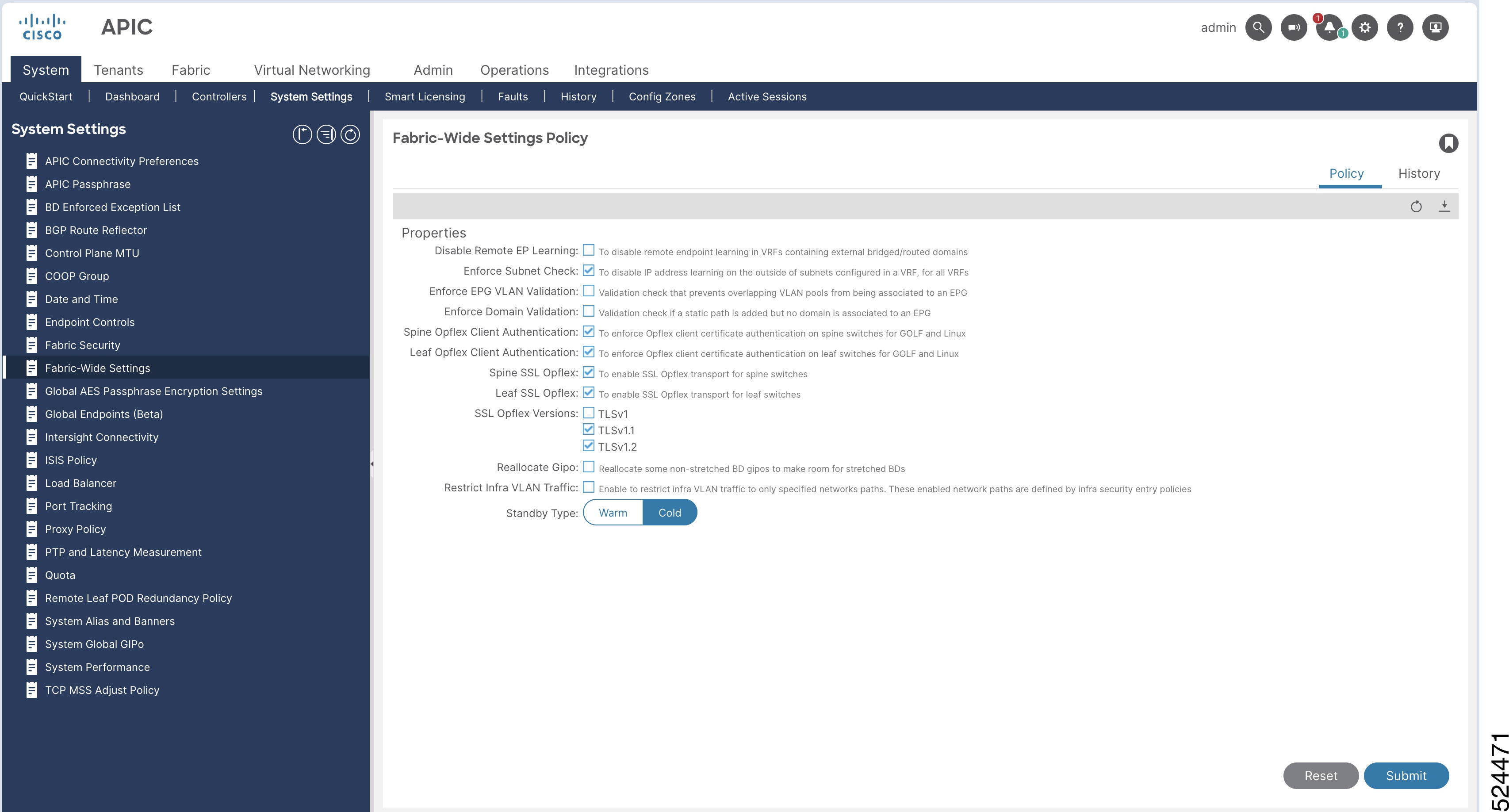
Starting from Cisco APIC 6.1(2), Standby APIC can be setup as a Warm Standby APIC as opposed to a Cold Standby APIC. Unlike Cold Standby APIC which does not contain any data until it’s promoted to active, Warm Standby APIC constantly synchronizes all data from the active APIC nodes while it’s still in the standby role. This enables you to rebuild the APIC cluster by using the Warm Standby APIC when some or all piece of the database is distributed across the APIC cluster is lost forever. Some such scenarios are explained below.

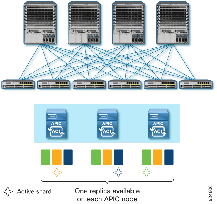
APIC Cluster uses a database technology called sharding and replica. The data of the ACI fabric is divided into smaller, separate parts called shards and distributed across active APIC nodes. Each shard is replicated up to three replicas regardless of the size of your cluster. For instance, if you have a cluster of 5 APIC nodes, one shard is replicated on APIC 1, 2, and 3 while another shard is replicated on APIC 3, 4, and 5. This means that if you loose three or more APIC nodes in the cluster, data for some shard(s) will be completely lost even if you still have some active APIC nodes. In such a case, the Cold Standby APIC cannot replace those lost APIC nodes because the Cold Standby APIC does not contain any data by itself and cannot restore those lost shards from any of the remaining active APIC nodes. Similarly, if you lost all APIC nodes in the cluster, Cold Standby APIC cannot replace them either regardless of the number of APIC nodes you lost.

For these scenarios, a Warm Standby APIC can be used. Some practical examples of such data loss scenarios are as follows.

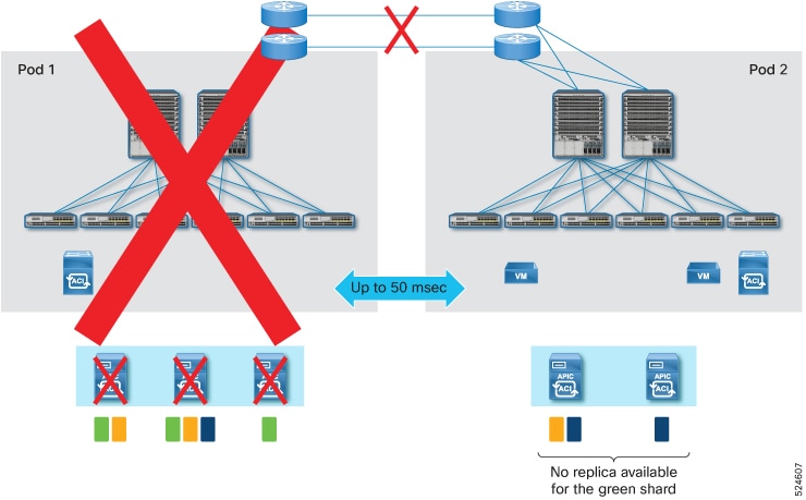
Data loss scenario 1:

In a multi-pod deployment where you have APIC 1, 2, and 3 in Pod 1 and APIC 4 and 5 in Pod 2, if Pod 1 goes down because of a disaster, such as flood, fire, earthquake, and so on, three APIC nodes are lost. This means some database shards are completely lost.

Data loss scenario 2:

In a multi-pod deployment with Pod 1 and 2 in the same location while Pod 3 and 4 in another location where you have APIC 1 and 2 in Pod 1, APIC 3 and 4 in Pod 2, APIC 5 and 6 in Pod 3 and APIC 7 in Pod 4, if the location with Pod 1 and 2 has a disaster, four APICs (APIC 1, 2, 3 and 4) are lost. This means some database shards are completely lost.

Data loss scenario 3:

In a multi-pod deployment where you have APIC 1 and 2 in Pod 1, APIC 3 in Pod 2 and no active APIC in Pod 3, if Pod 1 and 2 goes down because of a disaster, all data of the fabric is lost in the cluster as you lose all active APIC nodes.

For these scenarios, if you have a Warm Standby APIC in the healthy pod/site, you can restore the lost data shard and restore the fabric because the Warm Standby APIC had all shards synchronized from all the active APIC nodes while they were still operational. This is not possible with the Cold Standby APIC.

These examples are all multi-pod deployments because it’s unlikely for a single pod deployment to lose more than three APIC nodes or all APIC nodes in the cluster while the standby APIC nodes are intact. Nevertheless, a Warm Standby APIC is supported and functions in the same way for both multi-pod and single pod deployments.

As shown with these examples, the new capability introduced with the Warm Standby APIC is disaster recovery where some or all the database shards are lost and the APIC cluster needs to be re-built in addition to the capability of a faster and easier replacement of an active APIC node which is supported by both Warm and Cold Standby APIC.

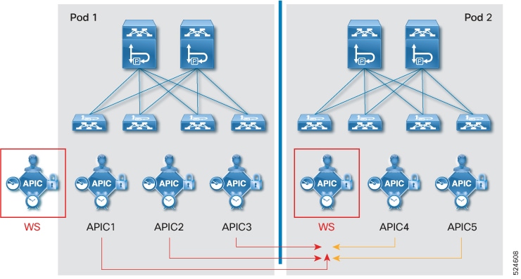
When you need to replace one active APIC node with a Warm or Cold Standby APIC node, the replacement operation is triggered 
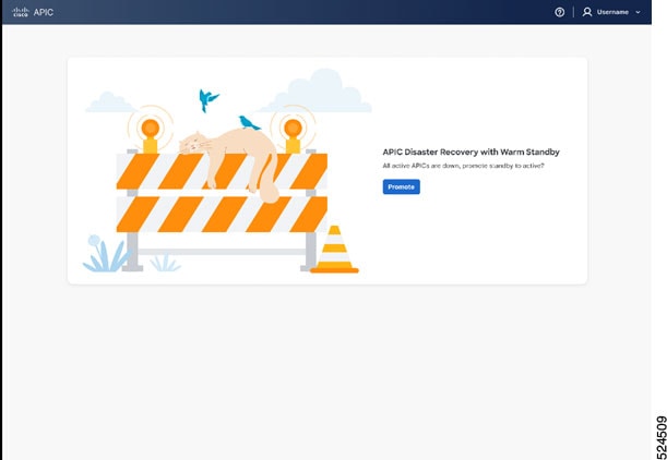
from one of the remaining healthy active APIC nodes. However, the promotion of the Warm Standby APIC to rebuild the cluster in the case of data loss, is not performed via the remaining healthy active APIC nodes because there may be no active APIC nodes left. It can be performed via the GUI or REST API on one of the Warm Standby APIC nodes. This always promotes the Warm Standby APIC to APIC 1 such that it can be the starting point of the disaster recovery. See the Recover an APIC cluster using Warm Standby and the GUI section for details.

For Warm Standby APIC to restore the fabric from disastrous events, it is recommended to have one Warm Standby APIC node at a minimum on each failure domain which may be a pod or a geographical site.

Guidelines for using Warm Standby Cisco APICs

Follow these requirements when configuring and managing Warm Standby Cisco APICs:

  • In Cisco APIC 6.1(2), a warm standby APIC supported APIC clusters only on physical APIC nodes. Beginning with Cisco APIC 6.1(3), standby APICs for APIC clusters with virtual nodes are also supported. Standby APICs must be of the same form factor (physical or virtual) as the active APICs in the cluster.

  • A Warm Standby APIC is supported for both types of APIC connectivity – directly attached and remotely attached via a L3 network.

  • Configure only one type of standby APIC (Cold or Warm) per cluster. Cold and Warm Standby APICs cannot coexist in the same cluster. Set or modify the type before or after adding standby nodes.

    Beginning with Cisco APIC 6.2(1), only the warm standby controller type is available. Cold standby controllers are deprecated and are not supported in this or later releases.

  • Limit the number of Warm Standby APIC nodes to a maximum of three per cluster.

  • Do not change the standby APIC type to Warm if four or more Cold Standby APIC nodes exist in the cluster.

  • In Cisco ACI 6.2(1) and later, upgrading fails if more than three cold standby nodes are present. Reduce the number of standby nodes to three before upgrading; these nodes are converted to warm standby by default during the upgrade.

  • Disaster recovery with Warm Standby APIC to rebuild the entire cluster is allowed only when there is data loss in the cluster, in other words only when three or more active APIC nodes are lost and as a result all three replicas of some shard are lost forever.

    -
  • When three or more active APICs are lost temporarily because of a network issue in the Inter-Pod Network (IPN), you should not promote the Warm Standby APIC node to APIC 1 as you must initialize all other APICs and rebuild the cluster even when the APIC nodes are healthy in each pod.

  • You must change the Standby APIC Type of the cluster to Cold before you downgrade to a version older than 6.1(2) that does not support the Warm Standby APIC.

  • Prior to Cisco APIC 6.1(2) which only had the Cold Standby APIC, the upgrade (or downgrade) of standby APIC nodes was not visible. You did not have to wait before you proceeded with a switch upgrade. The standby APIC nodes were initialized and booted up with a new version after the APIC upgrade for the active nodes were completed.

    Starting from Cisco APIC 6.1(2), the APIC upgrade process may take a little longer than before when there are standby APIC nodes. The upgrade process explicitly includes standby APIC nodes for both Warm and Cold Standby APICs. This is to ensure that the database is backed up in the Warm Standby APIC and is updated to match the new version models. Although, the Cold Standby APIC does not contain any data to be updated, the same process is applied to the Cold Standby APIC, but this process completes much faster than the Warm Standby APIC.

  • You can delete a Standby node from the cluster. Refer to Delete a standby from the cluster for more information.

  • If any switch is unavailable during disastor recovery due to reboot, interface down, process crash, power failure etc., then Cisco recommends you do a clean reboot and rediscover the switch back into fabric.

  • If a Cisco APIC cluster is running in Strict mode on Cisco APIC 6.1(2) or later and the switches are running versions earlier than Cisco APIC 6.1(1), disaster recovery operations fail. The cluster must be switched to Permissive mode before performing disaster recovery.

Change the standby APIC type using the GUI

Complete this procedure to change the standby type on Cisco APIC.

Before you begin

Ensure you have administrator access to the Cisco APIC interface.

Procedure


Step 1

Navigate to the System > System Settings sub menu.

Step 2

In the Fabric Wide Settings Policy page, select Warm or Cold as the Standby Type.

Step 3

Click Submit.

Step 4

To verify the Warm Standby status:

  1. On the menu bar, choose System > Controllers.

  2. In the Navigation pane, expand Controllers > apic_controller_name > Cluster as Seen by Node.

  3. In the Work pane, the standby controllers are displayed under Standby Controllers.

  4. The Standby Type is displayed in the Cluster As Seen by Node pane.


The selected standby APIC type is changed and the status is confirmed in the controllers view.

Add a standby APIC

Adding a standby APIC allows your Application Policy Infrastructure Controller (APIC) cluster to remain operational if a primary controller fails, ensuring continuous management of your fabric.

Follow these steps to add a standby APIC:

Before you begin

  • Make sure you have administrator access to the APIC system.

  • Gather CIMC or management credentials and network information for the APIC to be added.

  • Confirm your network policies allow communication between controllers.

Procedure


Step 1

On the menu bar, choose System > Controllers.

Step 2

In the Navigation pane, expand Controllers > apic_name > Cluster as Seen by Node.

The Cluster as Seen by Node window appears in the Work pane.

Step 3

In the Work pane, click Actions > Add Standby Node.

Step 4

In the Controller Type field, either Physical or Virtual is pre-selected as the same type as the active controllers in the cluster.

Step 5

In the Connectivity Type field, select CMIC or OOB For virtual APICs, OOB is pre-selected as the only option.

Step 6

In the CMIC Details pane or the Management IP pane, enter the following details:

  1. IP Address: Enter the CIMC IP address.

  2. Username: The username to access the CIMC

  3. Password: Enter the password to access CIMC.

Step 7

In the General pane, enter the following details:

  1. Name: Enter a name for the controller.

  2. Controller ID:Enter a value for the Controller ID. We recommend that you add a value in the range of 21 to 29 for this ID.

  3. Pod ID: Enter the pod ID for APIC. The range is from 1 to 128.

  4. Serial Number: The serial number is auto-populated (for APICs 1 to N, where N is the cluster size) after CIMC validation.

    APIC 1 verifies the reachability of the CIMC IP address and also captures the serial number of the new APIC.

Step 8

In the Out of Band Network pane, enter the following details:

  1. IPv4 Address: Enter the IPv4 address.

  2. IPv4 Gateway: Enter the IPv4 gateway address.

If you have enabled IPv6 addresses for OOB management, enter the IPv6 address and gateway.

  1. IPv6 Address: Enter the IPv6 address.

  2. IPv6 Gateway: Enter the IPv6 gateway address.

Step 9

Click Apply.


The standby APIC is added to the cluster and is ready to serve as a backup controller if needed.

What to do next

  • Verify the new standby APIC appears in the cluster and monitor its health status.

  • Perform any additional configuration as required by your environment.

Delete a standby from the cluster

Perform this task when you need to delete a warm standby node from the cluster and prepare it for future reuse or decommissioning.

Follow these steps to delete a standby node from the cluster:

Before you begin

Shut down the standby node you plan to delete. See the Guidelines and Limitations for Warm Standby on Cisco APICS for more information.

Procedure


Step 1

On the menu bar, choose System > Controllers.

Step 2

In the Navigation pane, expand Controllers > apic_controller_name > Cluster as Seen by Node.

Step 3

In the Controllers pane, select the node and click Actions>Delete Nodes.

Note


Shutdown the node that must be deleted and then delete the node. Once you have deleted the node, it must be disconnected from the fabric. You cannot add the deleted standby node back to the cluster until you have performed a factory reset for this node.


The selected standby node is removed from the cluster.

What to do next

  • Physically disconnect the deleted node from the network.

  • To add this node back to the cluster in the future, perform a factory reset on it.

Recover an APIC cluster using Warm Standby and the GUI

As explained in the “Warm Standby” section, one of the use cases of Warm Standby APIC is to rebuild the APIC cluster even when some or all the database information (shard) is lost along with the active APIC nodes. See the Warm standby for a Cisco APIC cluster section for details of the data loss scenarios that need recovery with a Warm Standby APIC.

To rebuild the APIC cluster to restore the fabric from a disastrous event that caused the data loss in the APIC cluster, you can access the GUI or REST API of one of the Warm Standby APIC nodes and follow the procedure shown below.

The procedure in this section will promote the Warm Standby APIC node to APIC 1 using the database information in the standby node itself. Once the Warm Standby APIC node is successfully promoted to APIC 1, initialize the remaining active and/or standby APIC nodes and discover them as new active APIC 2, APIC 3 and so on. As the new APIC nodes are discovered, the data stored in APIC 1, which used to be the Warm Standby APIC node will be distributed to those new nodes as the new replica of each shard.


Note


When the Warm Standby APIC node is promoted to APIC 1, the standby APIC node shuts down the infra interfaces on the remaining active or Standby APICs that are still reachable to ensure that the ACI switches can only see the standby node, soon to be new APIC 1, to avoid any conflict with the remaining active APIC nodes


Complete this procedure to setup the Cisco APIC Disaster Recovery for Cisco APIC.

Before you begin

  • Confirm you have administrator credentials for the Warm Standby APIC node.

  • Identify which APIC nodes are available and which have been lost.

Procedure


Step 1

Login into one of the Warm Standby APIC by accessing https://<standby APIC OoB IP>. Admin user password is required.

Step 2

Click Promote to start re-building the APIC cluster by promoting the Warm Standby APIC to APIC 1.

Note


If a Cisco APIC cluster does not need disaster recovery, you are redirected to an active APIC UI.

Step 3

The Initiation Progress status is displayed. If successful, the active Cisco APIC is displayed. The GUI will transition to the regular APIC GUI with the former standby node as new APIC 1. You will use this GUI to add a new APIC 2, APIC 3 and so on in the following steps.

Step 4

Initialize the remaining APIC nodes with acidiag touch setup then acidiag reboot via the CLI on each node.

Step 5

Add the initialized APIC nodes as the new APIC 2, APIC 3, and so on via the APIC GUI on the new APIC 1. See Expand the APIC cluster using the Add Node optionfor details.


After rebuilding, the promoted Warm Standby node serves as APIC 1. Additional nodes join as APIC 2, APIC 3, and synchronize data. The fabric is restored.

APIC migration types

APIC migrations are controller transition processes that:

  • enable movement between physical and virtual APIC clusters,

  • support migration among clusters of different APIC types: physical, virtual, or mixed

  • facilitate the migration of one or more standby nodes from a source cluster to a destination cluster.

Beginning with Cisco APIC release 6.1(1), APIC migrations support transitioning from a physical APIC cluster to a virtual APIC cluster deployed on ESXi hosts (using VMware vCenter) and from a virtual APIC cluster (on ESXi hosts) to a physical APIC cluster.

Starting with Cisco APIC release 6.2(1), APIC migrations support transitions between clusters composed of any mix of physical and virtual controllers. This release also introduces support for migrating one or more standby nodes from the source cluster to the destination cluster.

Guidelines and limitations for migrating physical APICs to virtual APICs

The following guidelines and limitations apply when migrating physical APICs to virtual APICs and vice versa:

Guidelines

  • Physical APICs in layer 2 (directly attached to the fabric) can be migrated to layer 2 virtual APICs, and layer 2 virtual APICs can be migrated to layer 2 physical APICs. Physical APICs in layer 3 (remotely attached to the fabric) can be migrated to layer 3 virtual APICs, and virtual APICs in layer 3 can be migrated to layer 3 physical APICs. Migration between layer 2 APICs and layer 3 APICs is not supported.

  • Do not initiate the migration process if an upgrade is in progress.

  • Do not initiate an upgrade if migration is in progress.

  • Update any configuration that uses APIC out-of-band (OOB) management after migration is completed.

  • If NDO (Network Domain Orchestrator) is configured, update connection details in NDO after migration, as the process changes OOB IP and subnet addresses.

  • If an SMU (Software Maintenance Update) is installed on the physical APIC, migration from physical to virtual APIC is not recommended for Cisco APIC release 6.1(1). Upgrade the cluster to an image that contains the SMU fix before migrating.

  • For app-infra, stop any running ELAM/FTRIAGE jobs prior to migration and restart them after migration is complete.

Limitations

  • Migration of standby nodes is not supported. Remove all standby nodes from the cluster before migration.

  • Migration is not supported for mini ACI fabric.

Migrating APIC clusters

The APIC cluster migration process transitions a three-node Cisco APIC cluster from physical (source) nodes to virtual (target) nodes to maintain continuous network operations.

The key components involved in the migration process are:

  • Source APIC nodes: The physical nodes currently running in the cluster (APIC 1, APIC 2, APIC 3).

  • Target APIC nodes: The virtual nodes that will form the new cluster after migration.

  • Administrator: The user who initiates and manages the migration workflow.

In this section, a high-level explanation of the migration process is provided. For the detailed steps, see the Migrate an APIC cluster between physical and virtual deployments procedure in the subsequent section.

Consider a three-node cluster; three source nodes and correspondingly three target nodes (after-migration nodes). The APIC with controller ID 1 is considered as APIC 1. Login to APIC 1 (IP address 172.16.1.1) and initiate the migration process.

Table 1. Sample APIC nodes

APIC

Source Node

Target Node

APIC 1

172.16.1.1

172.16.1.11

APIC 2

172.16.1.2

172.16.1.12

APIC 3

17.16.1.3

172.16.1.13

Stages in the migration process

  1. Log in to source APIC 1 (172.16.1.1), and initiate the migration process.

  2. Migration of source node APIC 3 (172.16.1.3) is initiated.

  3. Migration of APIC 3 is completed (to target node 172.16.1.13).

  4. Migration of source node APIC 2 (172.16.1.2) is initiated.

  5. Migration of APIC 2 is completed (to target node 172.16.1.12).

  6. Target APIC 2 takes control to enable the migration of APIC 1. This is called the handover process where in the control is passed on from source APIC 1 (172.16.1.1) to target APIC 2 (172.16.1.12). At this stage, a new window is displayed (URL redirected to target APIC 2). This is because, after successful migration, source APIC 1 is no longer part of the cluster (which now has the migrated target APICs).

The migration process is completed in the reverse order, that is, APIC N (APIC 3 in the example) is migrated first, followed by APIC N-1 (APIC 2 in the example), so on, and then finally APIC 1.

Migrate an APIC cluster between physical and virtual deployments

Use this procedure to migrate the nodes of a physical APIC cluster to a virtual APIC cluster (or vice-versa).

Before you begin

Following are the required prerequisites before you start with the migration process:

Cluster health

Confirm that the current APIC cluster is Fully fit.

Generic

  • Ensure that the source and destination APICs’ date and time are synchronized.

  • Ensure that all the controllers are on Cisco APIC release 6.1(1), and all the switches are running the same version as the controller.

Source and target nodes

  • For directly connected APIC migration, ensure both source and target nodes are on the same layer 2 network.

  • For remotely connected APIC migration, ensure both source and target nodes have infra network connectivity between them. This means the new target APIC should have the correct IPN configuration such that it can interact with the infra network of the fabric.

  • Target nodes have the same admin password as the source cluster.

  • Target nodes’ OOB IP address should be different while all other fields can be same or different from the source node. Infra addresses will remain same for layer 2 (directly attached); for layer 3 (remotely attached) cluster, they can be same or different based on deployments.

  • Source cluster and target cluster OOB networking stacks should match. For example, if source cluster is using dual stack (IPv4 and IPv6) for OOB, dual stack (IPv4 and IPv6) address details should be provided for target nodes too.

  • Ensure OOB connectivity between the source and destination APICs.

  • Ensure the OOB contracts and reachability for the new APIC are configured correctly; the migration process uses the OOB IP address to communicate between the APICs.

For virtual APIC to physical APIC migration

  • Ensure the physical APIC nodes are factory reset; use the acidiag touch setup and acidiag reboot commands.

  • For migration with/ without CIMC (applicable for physical APICs):

    If....

    Then....

    Using CIMC

    ensure that the physical APIC CIMC addresses are reachable from the OOB network of the virtual APIC.

    Not using CIMC

    ensure that the OOB IP address is configured manually on the physical APIC after factory-reset and use the OOB option for connectivity.

For Physical to virtual migration

  • Ensure that you have deployed the virtual APIC nodes as per the procedure in the Deploying Cisco Virtual APIC Using VMware vCenter guide.

  • If virtual APICs are deployed on a vCenter that is part of a VMM domain, ensure that Infrastructure VLAN is enabled on the AEP configured on the interfaces connected to the ESXi host(s) where the virtual APIC is deployed.

Procedure


Step 1

On the Cluster as Seen by Node screen, click Migrate (displayed in the Cluster Overview area).

All the available controllers in the cluster are displayed.

Note


The Migrate button is displayed only on APIC 1 (of the cluster).

Step 2

Click the pencil icon next to the Validate column, to start the migration process of the selected controller.

The Migrate Node screen is displayed.

Step 3

Enter the following details in the Migrate Node screen:

  1. For the Controller Type, select Virtual or Physical, as the case may be (migration from physical APIC to virtual APIC and vice-versa is supported).

  2. For the Connectivity Type, select OOB, if you are migrating a physical APIC to a virtual APIC. If you are migrating a virtual APIC to a physical APIC, you can either select the OOB option or the CIMC option.

    It is recommended to select the CIMC option for the virtual to physical migration. To use the OOB option, connect to the CIMC address of physical APICs and configure the OOB IP addresses manually before starting the migration process.

    Controller Type and Connectivity Type are auto selected based on the source controller type. If required, you can modify them.

  3. In the Management IP pane, enter the following (target APIC details) — Management IP address, Username, Password.

    or

    (applicable only for virtual to physical APIC migration) In the CIMC Details pane, enter the following details of the physical APIC— CIMC IP address, username and password of the node.

  4. Click Validate.

    After you click Validate, the details displayed in the General and Out of Band management panes change to match the details of the controller. The only editable fields are the Name and Pod ID (applicable only for layer 2), the other fields cannot be modified. For virtual to physical APIC migration, confirm the Admin Password too.

    Note


    If dual stack is supported, fill in the IPv4 and IPv6 addresses.

  5. In the Infra Network pane (applicable only for Layer 3, APIC is remotely attached to the fabric), enter the following:

    • IPv4 Address: the infra network address.

    • IPv4 Gateway: the IP address of the gateway.

    • VLAN: the interface VLAN ID to be used.

The OOB gateway and IP addresses are auto-populated in the table (based on the validation); click Apply. The validation status is displayed as Complete (on the Migrate Nodes screen).

Repeat the same process for the other APICs in the cluster by clicking the pencil icon (next to the Validation column). After providing all the controller details, click the Migrate button at the bottom of the Migrate screen.


Migration status

The migration process involves a series of activities, and this is displayed in stages. Each stage is indicated with a color-coded bar.

Figure 1. Migration Status

The Migrate Cluster Status screen displays the overall migration status, followed by the status of the apisever. The apiserver is the process that orchestrates the whole migration process. Below the apiserver status, the controller-wise migration status is displayed. The source IP address and the target IP address of the nodes are also indicated.

The apiserver status is indicated as 100% done (green bar) after the handover to APIC 2 is completed. At this stage, a new window is displayed (URL redirected to target APIC 2). Login to target APIC 2. A banner indicating that Migration is in progress is displayed at the top of the GUI until the migration is complete. After the handover process, the banner which was displayed on source APIC 1 is displayed on the target APIC 2. Click the View Status link on the banner to check the migration status.

You can also abort the migration process from source APIC 1 by clicking the Abort button available on the Migrate Cluster Status screen. The Abort button is displayed only after a certain period of time after initiating the migration.

After successful migration:

  • the migration status is no longer displayed. If the migration has failed, then a failure message is explicitly displayed.

  • to confirm if the target cluster is healthy and fully fit, navigate to System > Controllers > Expand Controllers. Expand Controller 1 > Cluster as seen by Node page.

  • verify if all the fabric nodes are in active state; navigate to Fabric > Fabric Membership.

  • if the Pod ID of the target APIC has changed, inband address for the node needs to be reconfigured on the Tenant Management screen. Navigate to Tenants > Mgmt > Node Management Addresses page.

Operations in case of a migration failure

The migration process may be interrupted due to a failure, or you may choose to abort the migration. In case the migration is not successful, it is recommended to revert or resume migration to either the source or target controller type. It is not recommended to have a APIC cluster in a migration failed state with a mix of physical and virtual controllers. Before attempting revert or resume, follow the steps in the next section, Basic Troubleshooting, to get the cluster to a healthy state.

If you choose to resume— the migration process is continued. On the Migrate Node screen (source APIC 1):

  1. Enter the details of all the target nodes based on the controller type you want to migrate to.

  2. Click Migrate.

If you choose to revert— the migration process is restarted. Migration process needs to be restarted after getting the controllers of the cluster to the initial (source) IP addresses.

  1. Factory reset each of the source APIC nodes which are being migrated using acidiag touch setup and acidiag reboot commands.

  2. On the Migrate Node screen, enter the source APIC details for all the nodes, as the migration process reverts the previously migrated APICs to the source controller type.

  3. Click Migrate.


Note


If the migration process fails after the handover process (control is passed on to target APIC 2 from source APIC 1), the migration cannot be resumed or reverted.


As mentioned earlier, the various sub-stages of migration with their completion progress are indicated as bars, for each controller. In case of failure at any stage, collect the relevant tech-support details and contact Cisco TAC for further assistance. To collect the logs for tech support, navigate to Admin > Import/Export > Export Policies > On-demand Tech Support > migration_techsuppport.

Basic troubleshooting

Consider a three-node cluster where in two nodes have migrated successfully, and a failure is detected during the migration of the third node. Check the status of the failed node. If the controller is not in the Fully fit state, the migration could fail.

Use this procedure to get the cluster to a healthy state:

Procedure


Step 1

(for migration failures with APIC 1) Check the cluster health from target APIC 2 by navigating to, System > Controllers. Select Controller 2 > Cluster as seen by Node screen.

or

(for migration failures with APIC 2 to N) Check the cluster health from source APIC 1 by navigating to, System > Controllers. Select Controller 1 > Cluster as seen by Node screen.

Step 2

If APIC 1 (or any other node of the cluster) is not Fully fit, click the three dots adjacent to the serial number of the controller. Select Maintenance > Decommission. Click Force Decommission as the node is not in a Fully fit state. Connect to the source APIC node N using SSH and factory-reset the node using the following commands - acidiag touch setup , acidiag reboot .

Step 3

From source APIC 1 navigate to, System > Controllers. Click Controllers > Controller 1 > Cluster as seen by Node screen.

or

From target APIC 2 navigate to, System > Controllers. Click Controllers > Controller 2 > Cluster as seen by Node screen.

Step 4

To commission a controller, click the three dots adjacent to the serial number of the controller. Select Maintenance > Commission. Enter the details, as required. Refer to the Commissioning a Node procedure (described earlier in this chapter). The only difference here is that the controller ID is pre-populated with the number corresponding to the ID of the controller in the cluster.

After the controller is commissioned, the cluster is indicated as Fully fit.

Step 5

Check the status of the cluster after commissioning the failed node. If the cluster is in a healthy state, resume the migration by clicking Migrate on the Cluster As Seen By Node screen. If the migration fails again, contact Cisco TAC for further assistance.


Manage APIC cluster at boot using the GUI

Follow these steps to build a new cluster, add a node to an existing cluster, and replace one of the nodes in the existing cluster with a new node at boot using the GUI.

Procedure


Step 1

Log in to the APIC using https://APIC-IP and enter the password.

  1. For virtual APICs:

    If you have completed the deployment of virtual APICs using ESXi (OVF template) or remote AWS (CFT), then you see the output on the VM console similar to this example:

    System pre-configured successfully.
    Use: https://172.31.1.2 to complete the bootstrapping.

    The IP address to access the bootstrapping GUI (APIC Cluster Bringup) is explicitly indicated, as shown in the example. You can proceed to step 2.

    After deploying Cisco APIC on AWS, keep the OOB management IP address handy to access the Cluster Bringup GUI. You can get the OOB management IP address from the Stacks Outputs tab on the AWS GUI.

  2. For physical APICs:

    Log in to the APIC KVM console using the CIMC; you will see a screen as shown:

    APIC Version: 6.0(2a)
    Welcome to Cisco APIC Setup Utility
    Press Enter Or Input JSON string to bootstrap your APIC node.

    If you see only a black screen on the KVM, connect to the CIMC using SSH and use serial over LAN (SoL) ("connect host") to connect to the console.

    On APIC, press Enter and provide the requested information. The IP address to access the bootstrapping GUI (APIC Cluster Bringup) is explicitly indicated.

    admin user configuration ...
      Enter the password for admin [None]:
      Reenter the password for admin [None]:
    Out-of-band management configuration ...
      Enter the IP Address [192.168.10.1/24]: 172.20.7.79/23
      Enter the IP Address of default gateway [192.168.10.254]: 172.20.6.1
    Would you like to edit the configuration? (y/n) [n]:
    System pre-configured successfully.
    Use: https://172.20.7.79 to complete the bootstrapping

    Note


    The admin password must be the same as the password of the existing cluster.

    The IP addresses displayed above are examples. The IP addresses will vary based on your deployment.

Step 2

In the Select Workflow screen of the APIC Cluster Bringup wizard, choose one of these workflows.

  • New cluster: Use this option to start a new cluster.
  • Cluster expansion: Use this option to add a node to an existing clsuter.
  • APIC replacement: Use this option to replace one of the nodes in the existing cluster with a new node.
  1. To start a new cluster, see Bring up the APIC cluster using the GUI.

  2. To add a node to the existing cluster, perform these steps:

    • In the Select Workflow screen, choose Cluster expansion and click Next.

    • In the Cluster Verification screen, enter the OOB IP address of the active APIC node and click Validate.

      The fabric and controllers information are displayed.

      Click Next after verifying the information.

    • In the Enter Node Details screen, enter a name for the controller and the Pod ID in the Controller Name field and Pod ID fields respectively.

      Note


      Pod ID is not required for Layer3 APIC.

    • (Optional) Check the Standby checkbox and enter a value in the Controller ID field.

      The range of standby controller ID is from 21 to 29.

      The Controller ID field is auto-populated with a value and disabled by default.

    • (Optional) Check the Force check box to force this configuration.

    • (Optional) Check the Enable IPv6 check box if you want to enable IPv6 addresses for out-of-band management and enter the IPv6 address and gateway.

      The IPv4 address and IPv4 gateway are auto-populated under the Out-of- band Network pane.

    • (For Layer3 APIC) Enter these details under the Infra L3 Network pane.

      • IPv4 Address: Enter the infra network address.

      • IPv4 Gateway: Enter the IP address of the gateway.

      • VLAN: Enter the interface VLAN ID to be used.

      Click Next.

    • In the Summary screen, review the information and click Deploy.

      The progress of operation is displayed in a screen.

  3. To replace one of the nodes in the existing cluster with a new node, perform these steps:

    • In the Select Workflow screen, choose APIC replacement and click Next.

    • In the Cluster Verification screen, enter the OOB IP address of the active APIC node and click Validate.

      The fabric and controllers information are displayed.

      Click Next after verifying the information.

    • In the Enter Node Details screen, choose a controller ID from the Controller ID drop-down list.

      Only the IDs of the decommissioned controllers are available in the Controller ID drop-down list.

      The controller name is auto-populated based on the selected controller ID.

    • Enter the Pod ID in the Pod ID field.

      Note


      Pod ID is not required for Layer3 APIC.

    • (Optional) Check the Force check box to force this configuration.

    • (Optional) Check the Enable IPv6 check box if you want to enable IPv6 addresses for out-of-band management and enter the IPv6 address and gateway.

      The IPv4 address and IPv4 gateway are auto-populated under the Out-of- band Network pane.

    • (For Layer3 APIC) Enter these details under the Infra L3 Network pane.

      • IPv4 Address: Enter the infra network address.

      • IPv4 Gateway: Enter the IP address of the gateway.

      • VLAN: Enter the interface VLAN ID to be used.

      Click Next.

    • In the Summary screen, review the information and click Deploy.

      The progress of operation is displayed in a screen.

      Note

       
      The user must manually reload the UI after this step to navigate to the main APIC UI.

Nexus Dashboard cluster from APIC GUI

Starting with APIC Release 6.1.4, users can directly navigate to a registered Nexus Dashboard cluster from the APIC GUI without the need for a separate login. The navigation is supported only if the Nexus Dashboard is running Release 4.1or later and the APIC is running Release 6.1.4 or later.

Only remote users with admin-write privileges on APIC can navigate from the APIC GUI to the Nexus Dashboard. A remote user refers to an APIC user authenticated through LDAP, RADIUS, or TACACS+. The logged-in user is granted super admin privileges on the Nexus Dashboard.

Navigate to Nexus Dashboard cluster from APIC GUI

Follow these steps to directly navigate to a registered Nexus Dashboard cluster from the APIC GUI without the need for a separate login.

See Connecting Clusters article to navigate to APIC from Nexus Dashboard.

Before you begin

  • Ensure that the NTP servers on both the APIC and Nexus Dashboard are configured to synchronize with the same time source.

  • APIC must be onboarded as a site within the Nexus Dashboard.

  • The user must log in to the APIC as a remote user.

  • The remote user must have admin-write privileges on the APIC. This user will have super admin privileges on the Nexus Dashboard.

  • Ensure that the client system is configured with the DNS domain for the Nexus Dashboard, as APIC uses the Nexus Dashboard's hostname for navigation.

Procedure


Step 1

Log in to the APIC GUI.

Step 2

Navigate to Nexus Dashboard cluster using one of these methods:

  • In the upper right corner of the APIC window, click the Launch the ND Cluster icon.

    The registered Nexus Dashboard clusters are displayed.

    Click the desired Nexus Dashboard cluster to navigate.

    APIC starts the active node in the Nexus Dashboard cluster.

  • On the menu bar, choose Integrations > Nexus Dashboard.

    The registered Nexus Dashboard clusters are displayed in a table.

    Check the desired cluster, click , and choose Open in New Tab to navigate to the Nexus Dashboard cluster.