Dynamic Creation of Transport Resources for VPN Services

This section explains the following topics:

Dynamic creation of transport resources for VPN services

The VPN Traffic Engineering (TE) Management is a solution that:

  • automates the setup and association of transport resources during VPN service deployment,

  • uses predefined templates and criteria to fulfill Service Level Agreements (SLAs) and Service Level Specifications (SLSs), and

  • eliminates manual transport policy configurations, enhancing efficiency and reliability.

Objective

Enable automatic fulfillment of SLAs and SLSs requests by dynamically creating and associating transport resources during VPN service creation.

Challenge

Network operators typically have to manually create and associate transport policies, such as SR-TE, RSVP, and ODN, for VPN services. This process is time-consuming and prone to errors. It involves configuring several transport resources, such as tag sets, destination prefix sets, IP prefixes, routing policies, and policy definitions, and then mapping these resources to services. It requires meticulous attention to detail to ensure proper configurations and adherence to SLAs and SLSs. As networks expand and service demands increase, operators must quickly respond to changing service requirements, while maintaining network integrity and reliability. This makes manual setup increasingly difficult in fast-growing, dynamic infrastructures.

Solution

The VPN TE Management feature transforms VPN service deployment by automatically handling the setup of necessary transport layer resources. Using predefined templates and criteria, the system dynamically creates and deploys TE policies required to meet the SLA or SLS configuration for the service without the need for manual pre-configuration and association. This one-step-automated solution checks for necessary tunnels and creates them between specified endpoints when required. It enables network operators to focus on strategic, higher-level tasks, improving efficiency and ensuring consistent reliability in service delivery.

How does VPN TE Management work?

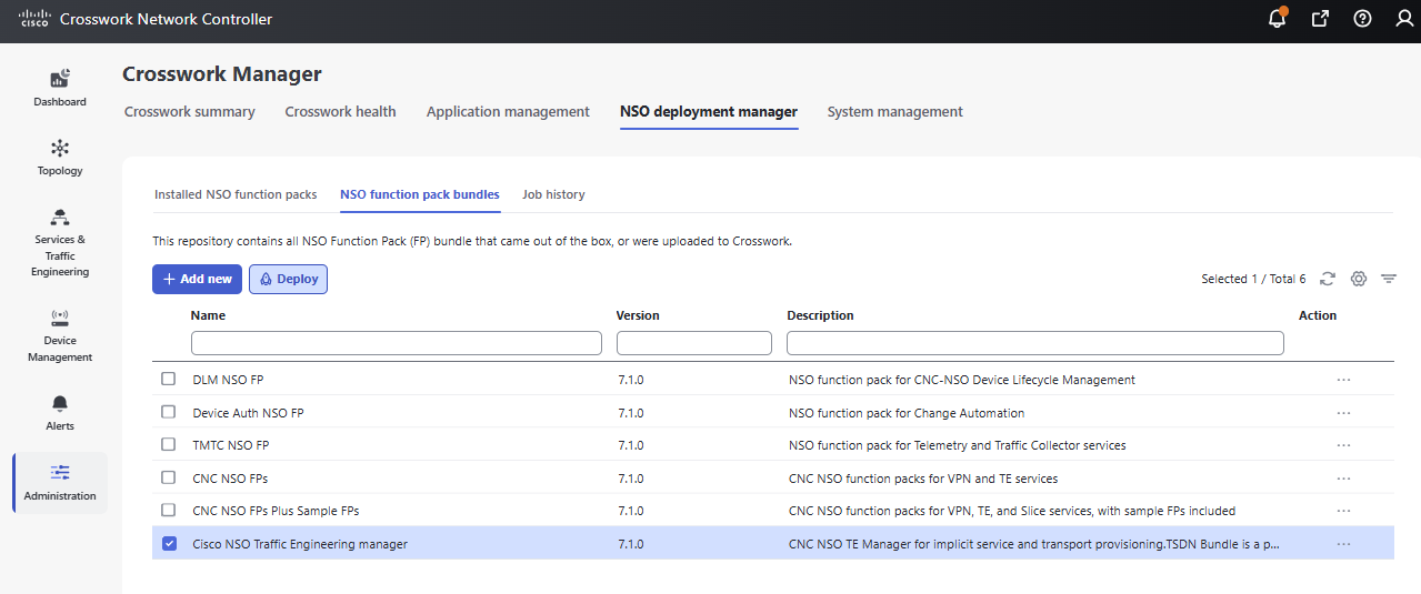
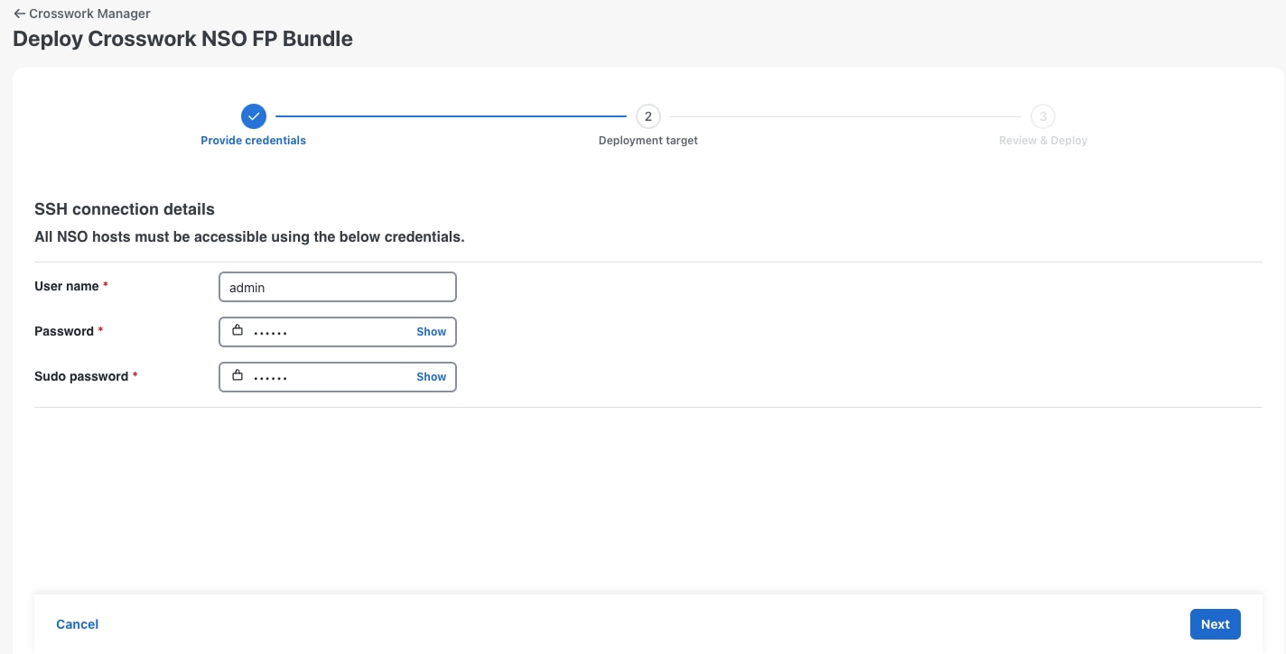
  1. The network operator deploys the Cisco NSO Traffic Engineering Manager function pack.

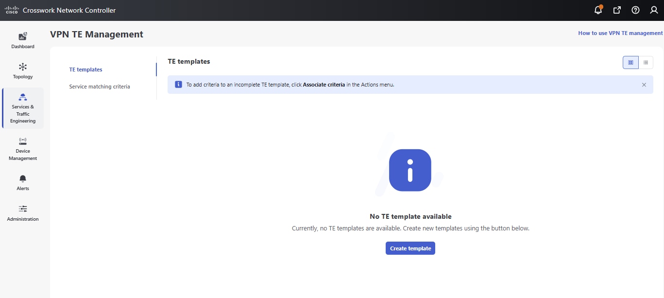
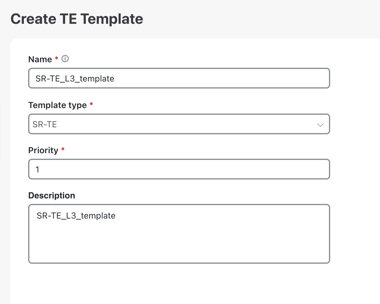
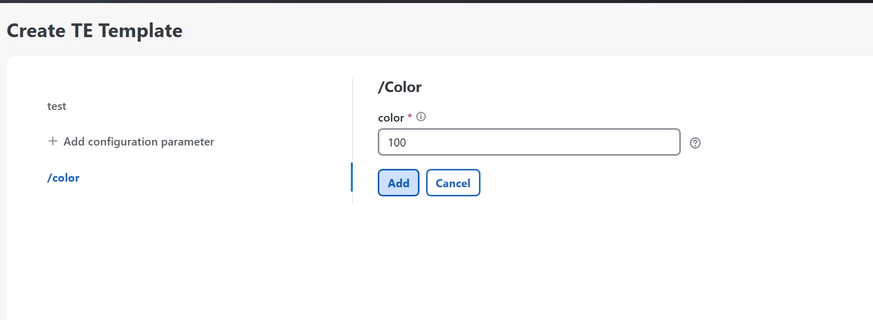
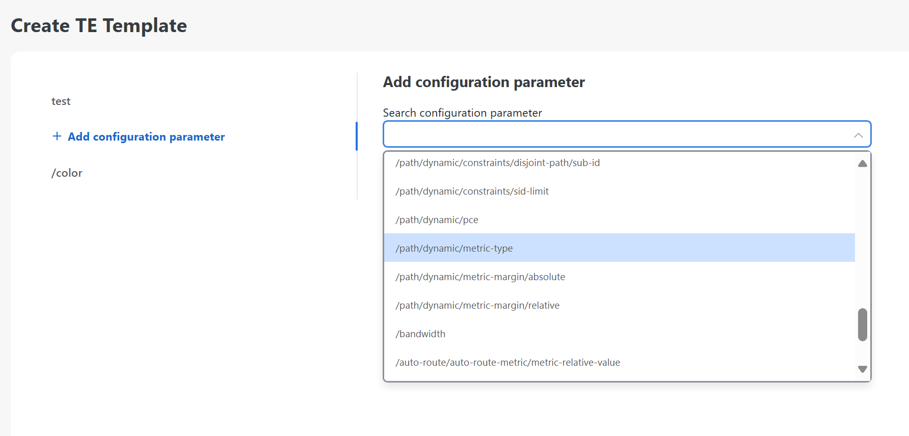
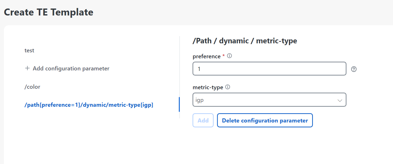
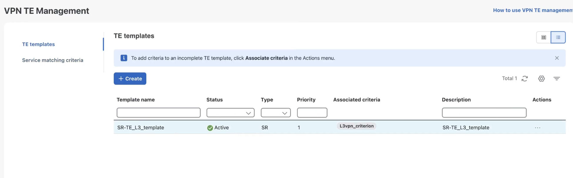
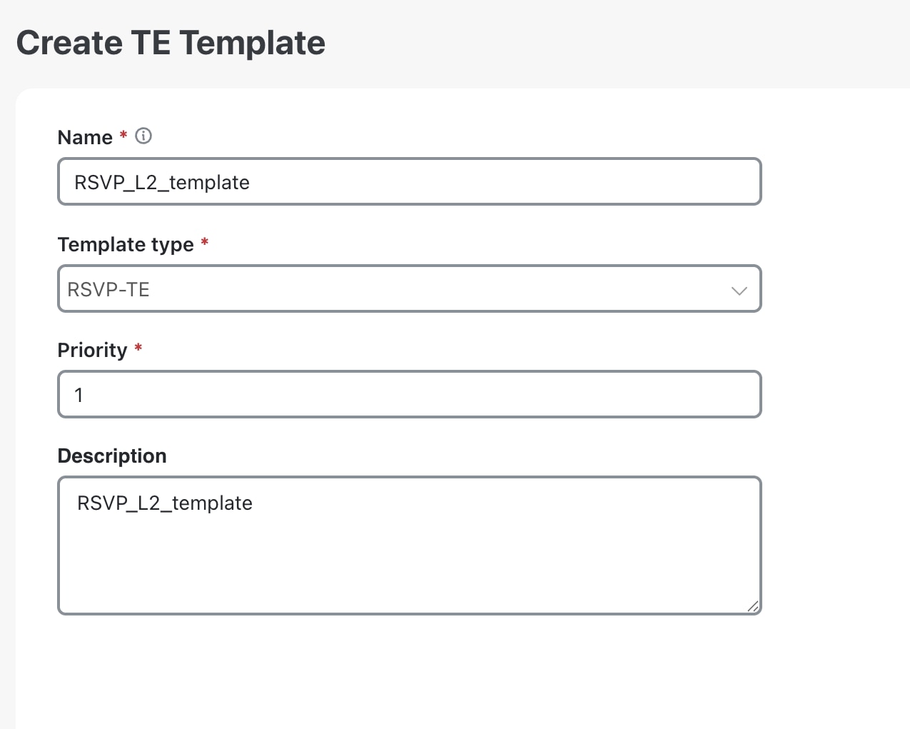
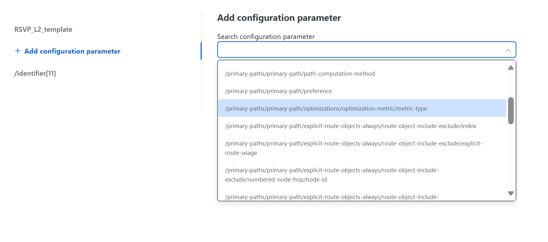
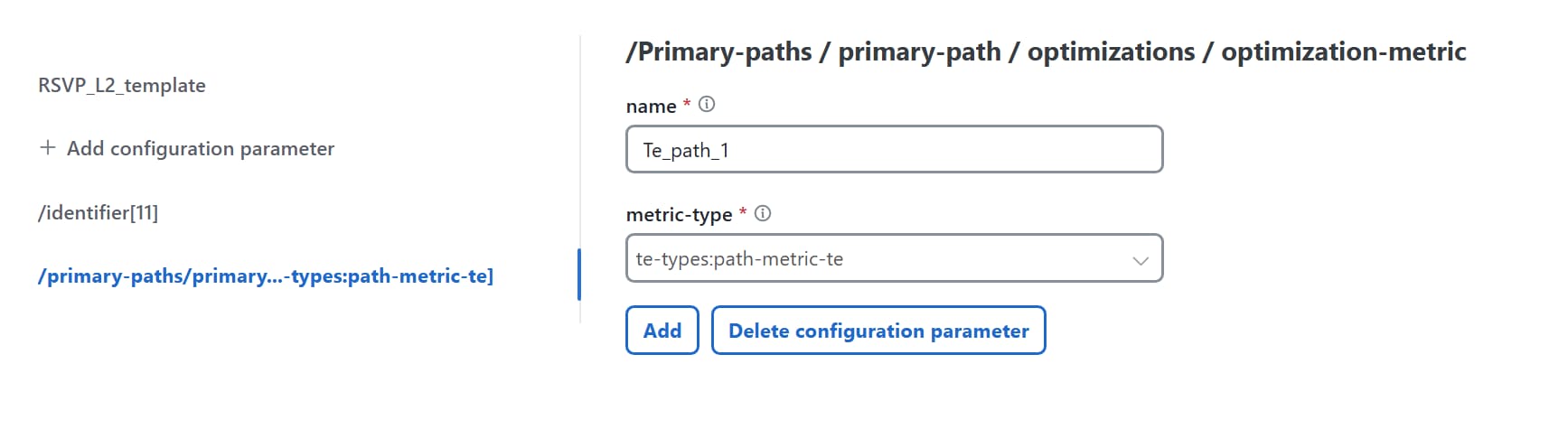
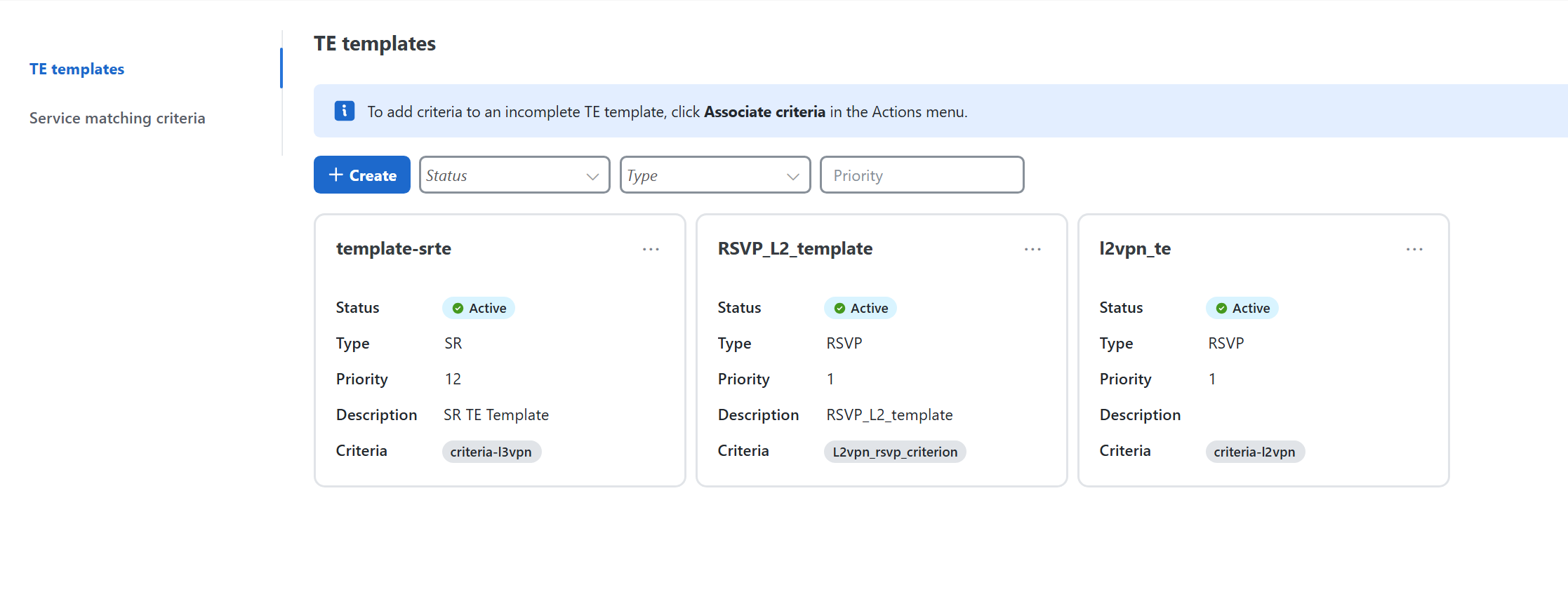
  2. The operator creates a TE template and specifies the required policy configuration settings for a TE policy. This policy can be an ODN, RSVP, or SR traffic engineering policy.

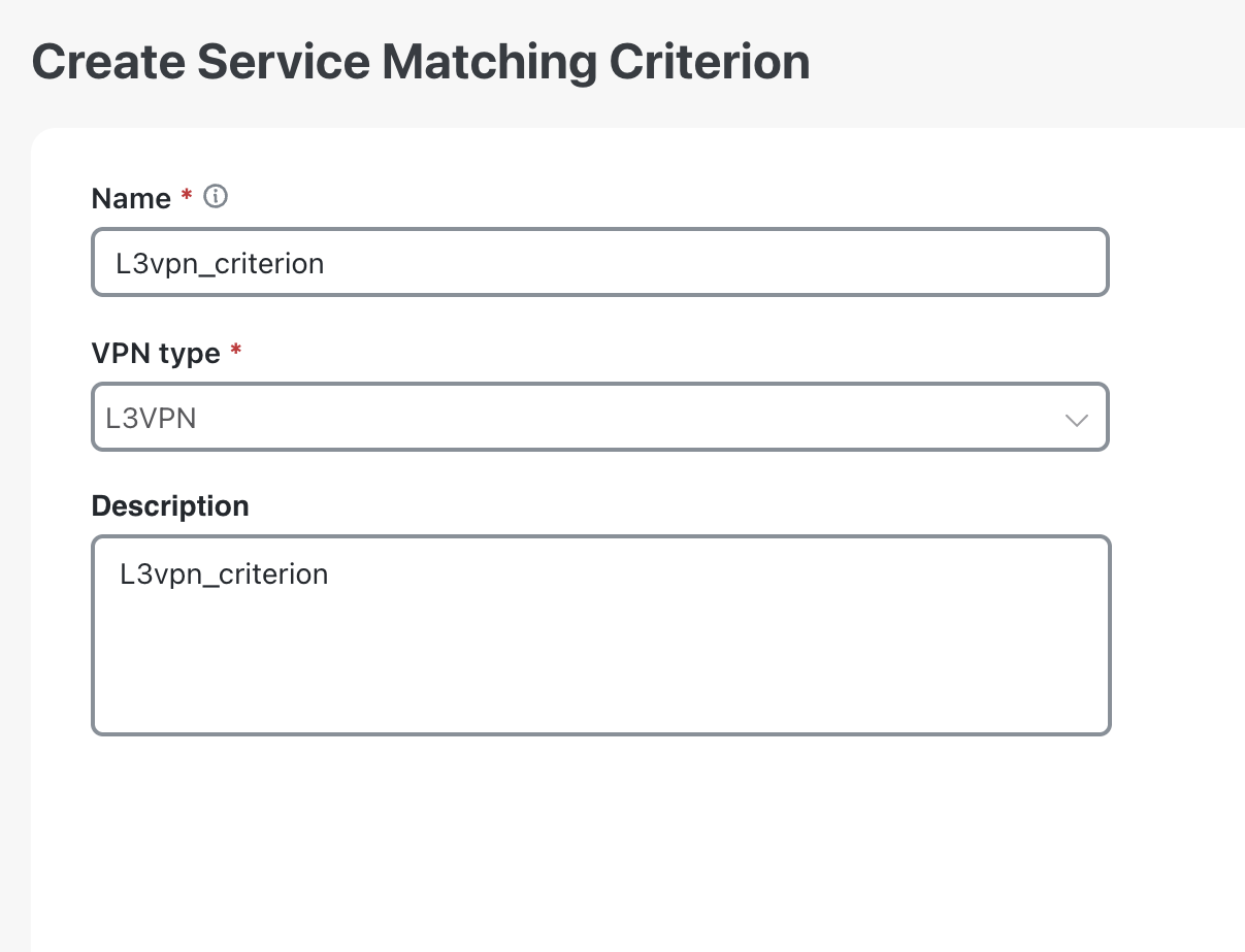
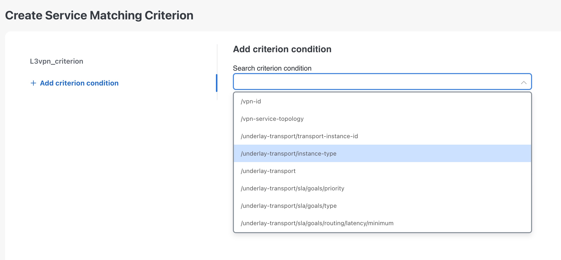
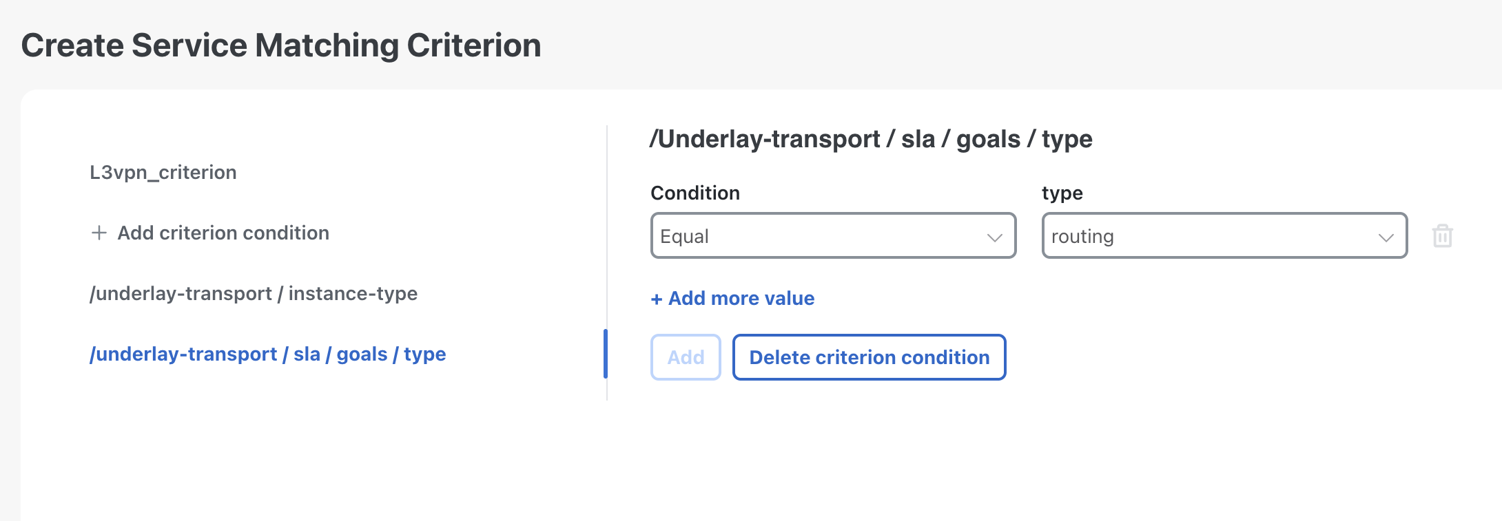
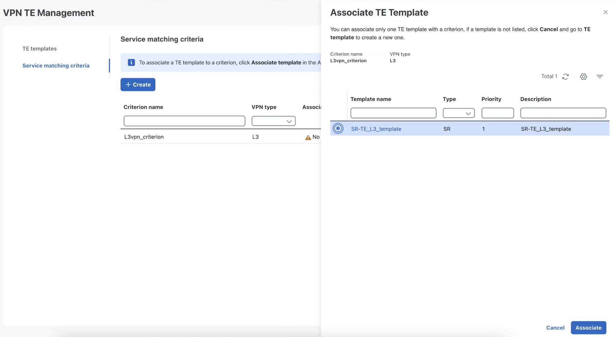
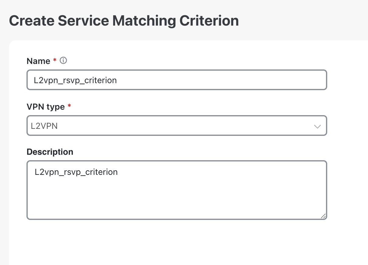
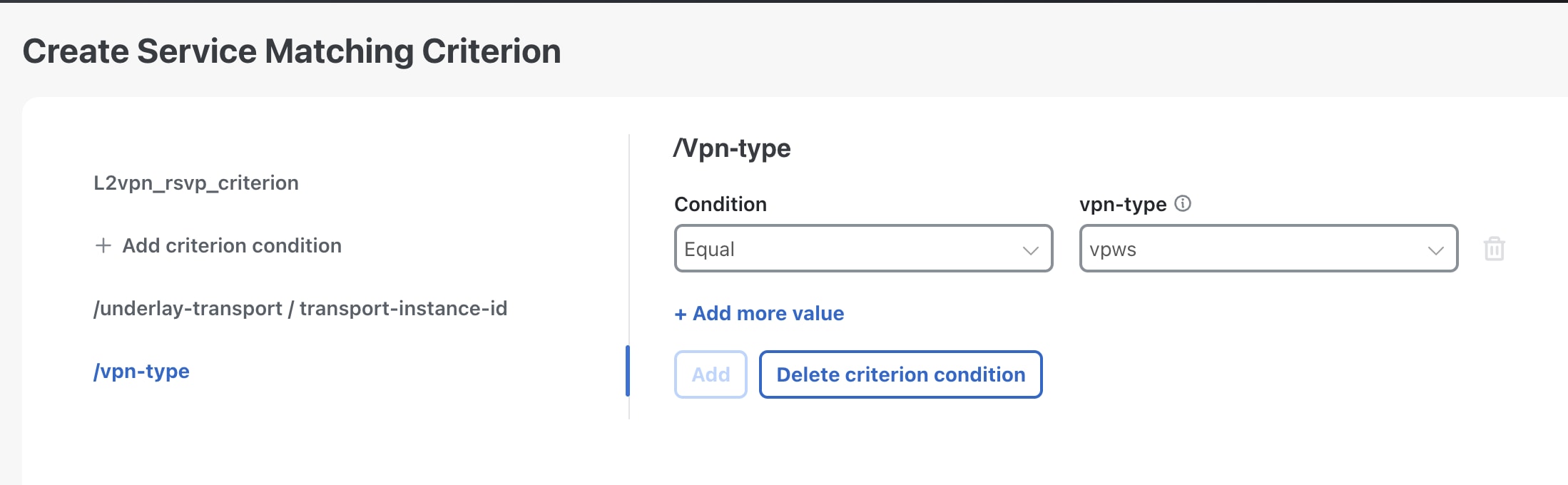
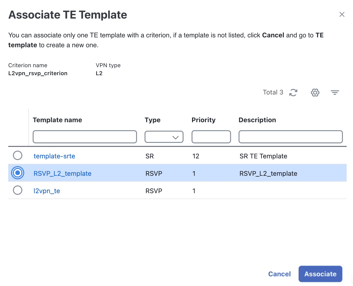
  3. The operator creates a service-matching criterion that defines the required conditions and parameters and associates it with a TE template.

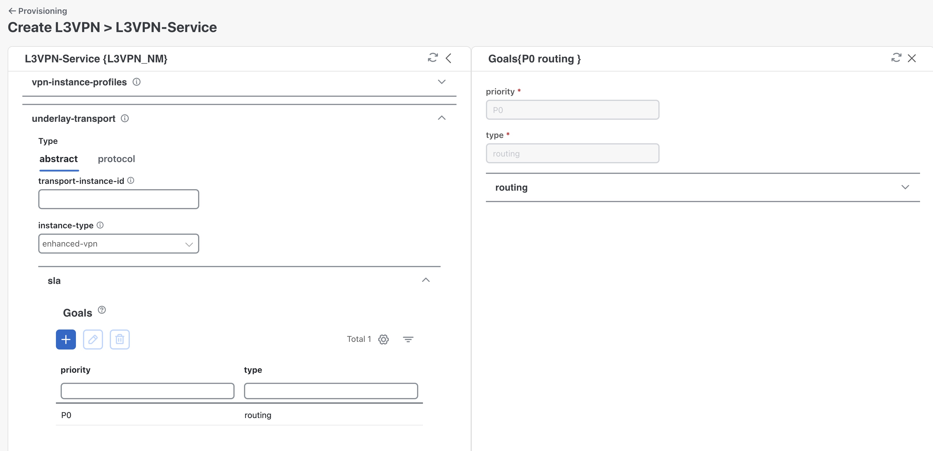
  4. When a VPN service is deployed with an SLA and SLS objective, Crosswork Network Controller tries to match the service's SLA goal to the pre-configured criterion. If the criterion parameter matches the service's SLA, Crosswork Network Controller identifies the associated TE template to create a new transport policy.

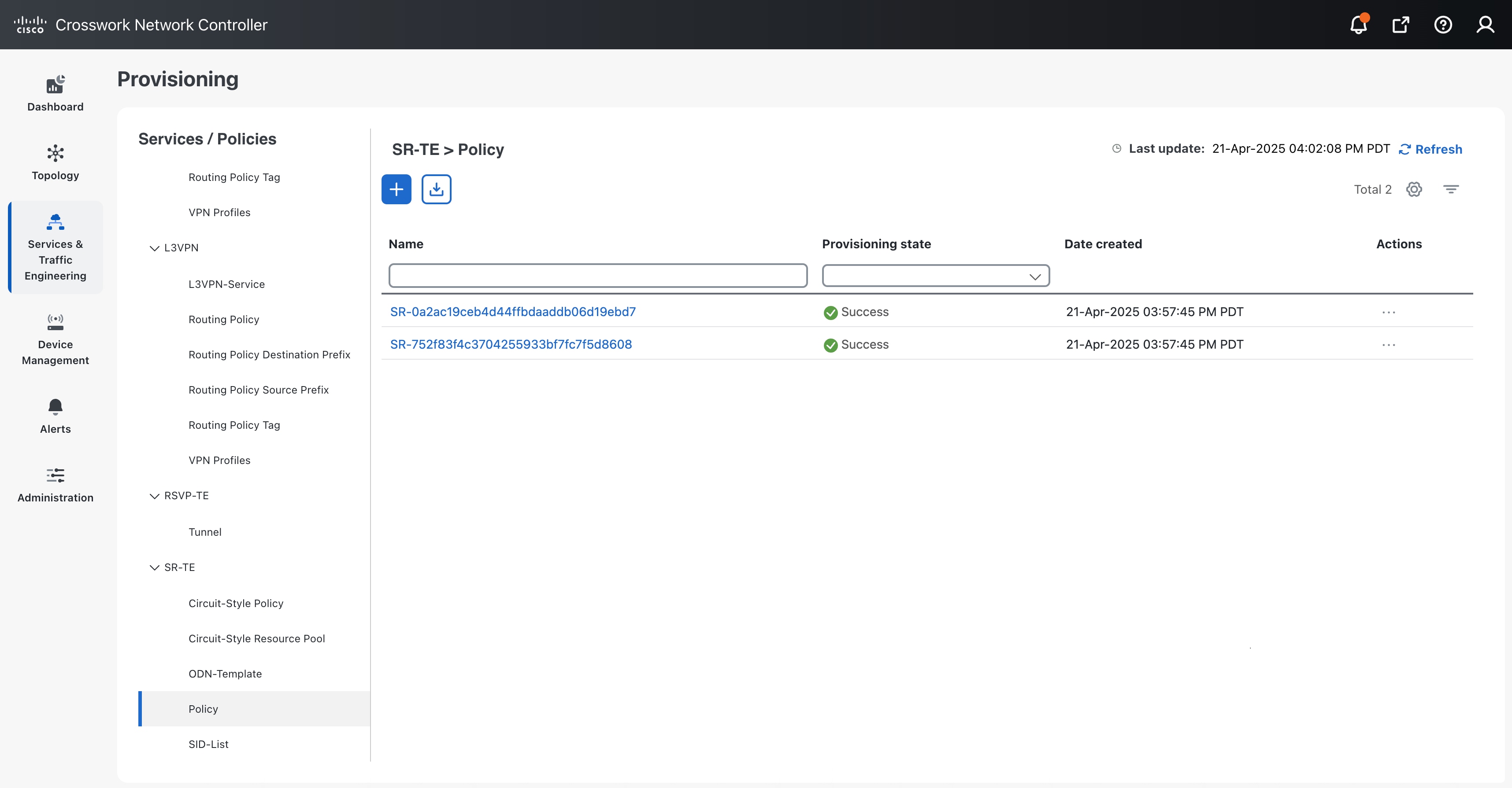
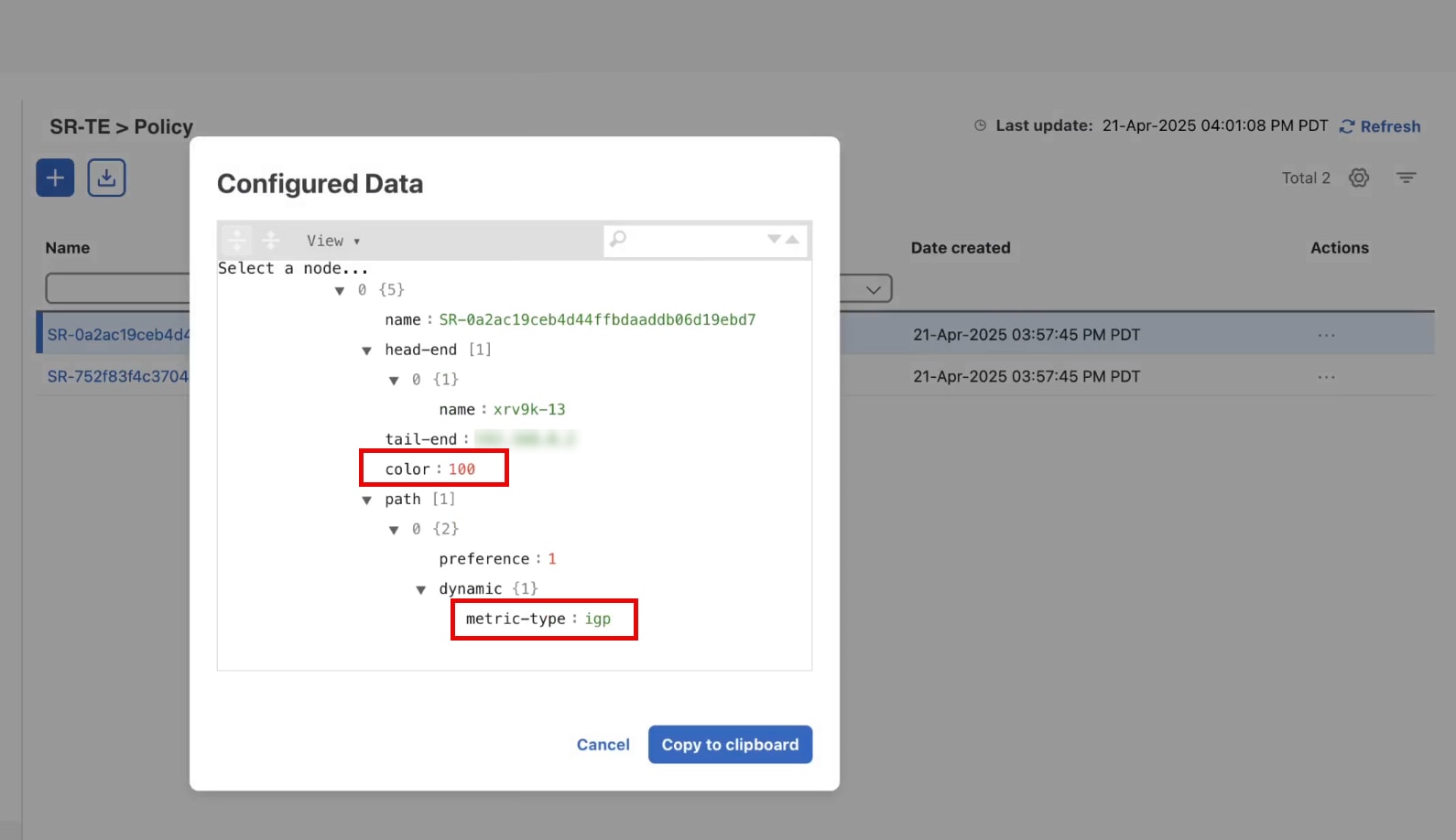
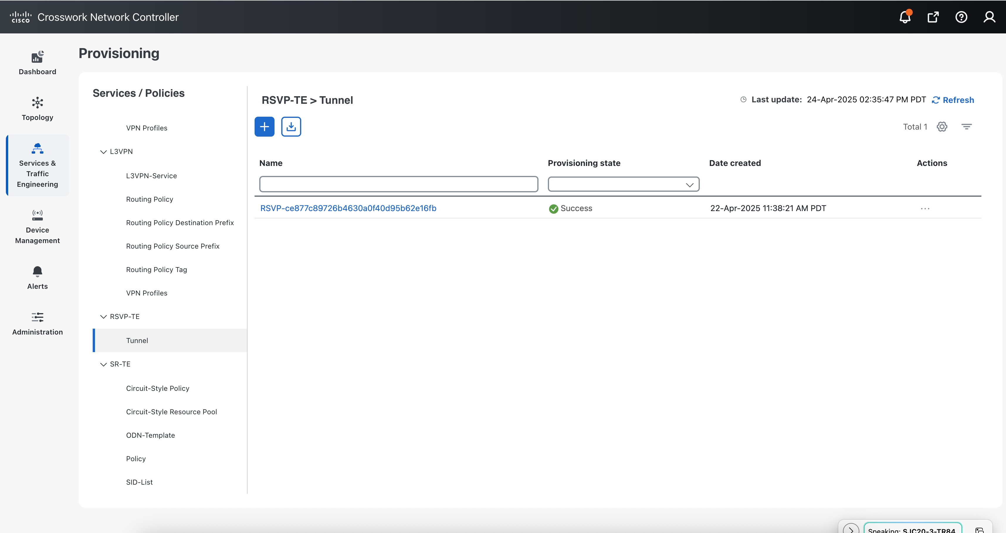
  5. Crosswork Network Controller creates and deploys the new policy and attaches it to the VPN service being created.

VPN TE Management key considerations

  • When the Cisco NSO Traffic Engineering Manager function pack is deployed, the Dry run feature for creating VPN services will show changes to the service-level configuration, but it will not display any changes to the underlay configuration. Additionally, when using the Dry run feature to edit services, any underlay configs in the device configuration will not be displayed.

  • RSVP template is not supported for L3VPN. When associating a template, if you filter the criteria by L3VPN type, only the SR and ODN templates will be available for association.

  • The Crosswork Network Controller validates conditions only during the deployment of a new service and not during the modification of an existing VPN service. The operator must recreate the service to apply modifications to the underlay constraints.

  • Deleting the ODN template will result in an error in the routing policy. If you delete the ODN template manually, it is not dynamically recreated.

  • Simultaneously creating or deleting multiple services on the same device can lead to commit queue conflicts in the associated policies. To prevent this, apply changes one at a time to minimize errors and deployment failures.

Assumptions and prerequisites

To use VPN TE Manager on the Crosswork Network Controller, you must meet these prerequisites:

  1. Install the Cisco NSO Transport SDN function-pack bundle.

  2. Deploy the NSO Traffic Engineering Manager function pack and ensure that it is up and running.

Workflow scenarios in this section provide examples of how to configure the system to achieve the intended operator configuration. These scenarios demonstrate only a fraction of the capabilities of the Crosswork Network Controller and highlight the platform flexibility. Further customization can be accomplished using resources on DevNet or by engaging with Cisco Customer Experience.

Deploy the NSO Traffic Engineering Manager function pack

Complete these steps to deploy the Cisco NSO Traffic Engineering Manager function pack.

Procedure


Step 1

From the main menu, choose Administration > Crosswork Manager and click the NSO deployment manager tab.

Step 2

Click the NSO function pack bundles tab.

Step 3

Select the Cisco NSO Traffic Engineering Manager function pack and click Deploy.

Figure 1. NSO function pack bundles tab
NSO function pack bundles tab

Step 4

On the Deploy Crosswork NSO FP Bundle page, enter these SSH connection details and click Next:

  1. User name: The SSH username for server access.

  2. Password: The SSH password for server access.

  3. Sudo Password: The SSH sudo password.

Figure 2. Provide credentials
Provide credentials

Step 5

In the Deployment Target section, review these target details and click Next.

  1. Provider Name: The name of the provider.

  2. Reachability: The reachability status of the provider.

  3. CFS Role Selection: This feature appears when a role is not assigned to a provider. The customer-facing service (CFS) and resource-facing service (RFS) are intended for LSA deployments and are not supported for TE Management functionality.

  4. High Availability: Depending on your deployment preferences for the function packs bundle on an NSO node, select either non-HA or HA. If HA is selected, enter the server details in the Primary Server and Secondary Server fields.

Step 6

On the Review and Deploy page, review the NSO bundle and deployment target details that you have configured, and click Deploy.

Note


If the provider is deployed on a standalone NSO node, the role is displayed as STANDALONE.

Step 7

Check Job History to monitor the installation status. The status changes from "pending" to "in progress", and finally to "succeeded".

Step 8

Click the Installed NSO function packs tab. Expand nso for a list of installed function packs.

Figure 3. cisco-te-manager function pack installed
cisco-te-manager function pack installed

The cisco-te-manager function pack is installed, and the Oper status shows Up.


Scenario: Implement automatic creation of SR-TE policy for an L3VPN service

Summary

This scenario explains how to implement the automatic creation of an SR-TE policy for an L3VPN service based on SLA objectives.

Workflow

In this scenario, we will:

  1. configure an SR-TE template (SR-TE_L3_template) with these configuration parameters:

    • Color: 100

    • Dynamic path metric type: IGP metric with a preference of 1

  2. define criteria (L3vpn_criterion) with these underlay transport conditions:

    • Instance type: enhanced-vpn

    • Intent type: routing

  3. associate the criteria with the template.

  4. create and deploy an L3VPN service with underlay transport constraints. In this scenario, we will specify the same constraints as defined in the criteria conditions. The Crosswork Network Controller will evaluate these constraints against the criteria conditions and parameters. When a match is found, it will select the associated TE template for policy creation. In this case, the selected template would be SR-TE_L3_template.

  5. confirm the deployment of the new SR-TE policy and the L3VPN service.

Step 1 Create TE template with the required policy configuration settings

In this step, we will create an SR-TE template and specify the color and dynamic path metric type as policy configuration parameters.

Procedure


Step 1

From the main menu, choose Services & Traffic Engineering > VPN TE Management.

Step 2

On the TE Template page, click Create template to create a new template.

Figure 4. TE Template page
TE Template page

Step 3

On the Create TE template page:

  1. Enter a name for the TE template. In this case, the name is SR-TE_L3_template.

  2. For the template type, select SR-TE.

  3. For the template priority, select 1. When multiple Traffic Engineering (TE) templates are available for policy creation, the Crosswork Network Controller uses priority settings to determine which template to select. Lower numbers signify higher priority.

    Note


    If multiple templates have the same priority, Crosswork Network Controller selects one at random.

    Figure 5. Create TE Template page
    Create TE Template page
  4. Click Continue.

Step 4

Click the mandatory /color parameter and specify a link color value. For this scenario, enter 100 and click Add.

Figure 6. Color parameter
Color parameter

Step 5

Click the Add configuration parameter link to add additional parameters.

Step 6

Click the Search configuration parameter list, which is populated from the NSO based on the selected template type.

Figure 7. Search configuration parameter list
Search configuration parameter list

Step 7

Select /path/dynamic/metric-type and specify the dynamic path settings:

  1. For preference, enter 1 to assign the highest priority to this path among all candidate paths. The lower the number, the higher the preference.

  2. For metric-type, select igp.

  3. Click Add.

Figure 8. Configured parameters
Configured parameters

Step 8

Click Save template. A message appears informing that the template has been created.

The new template appears on the TE templates page with an Incomplete status. To complete the template, you must associate it with at least one service-matching criterion.


Step 2 Create the service-matching criterion with the required conditions and parameters

In this step, we define a service-matching criterion with conditions and parameters according to the SLA. For this scenario, we choose these transport conditions:

  • Instance type: enhanced-vpn

  • Intent type: routing

Procedure


Step 1

Click Service matching criteria and then click + Create.

Step 2

On the Create service matching criterion page:

  1. Enter a name for the criterion. In this case, the name is L3vpn_criterion.

  2. For the VPN type, select L3VPN.

  3. Click Continue.

    Figure 9. Create service matching criterion page
    Create service matching criterion page

Step 3

Click the Add criterion condition link to add conditional parameters.

Step 4

Click the Search criterion condition list. This list is populated from the NSO based on the selected VPN type.

Figure 10. Search criterion condition list
Search criterion condition list

Step 5

Select /underlay-transport/instance-type and specify these entries in the respective fields.

  1. Condition: Equal

  2. Instance-type: enhanced-vpn

Note


Two or more equal conditions for the same criterion create conflicts, causing the condition to fail.

Step 6

Click Add.

Step 7

Click the Add criterion condition link again and select /underlay-transport/sla/goals/type as the criterion condition. Specify that the intent type should be routing, and click Add.

  1. Condition: Equal

  2. Type: routing

Figure 11. Configured conditions
Configured conditions

Step 8

Click Save condition. A message appears, indicating that the criterion has been created.

The new criterion appears on the Service matching criteria page.

Step 3 Associate TE template with criterion

To complete the template, you need to associate it with at least one service-matching criterion. You can add up to 10 criteria. In this step, we will associate the TE Template (SR-TE_L3_template) with the criterion (L3vpn_criterion).

Procedure


Step 1

Use these methods to associate the template with the criterion:

  • Click Associate in the message that appears after creating the criterion.
  • Alternatively, use the Actions menu on the Service matching criteria page or the TE templates page.

Step 2

In this example, we will associate the template through the Service matching criteria page. For the L3vpn_criterion, click Associate template in the Actions menu.

Step 3

In the Associate TE Template dialog, select SR-TE_L3_template and click Associate.

Figure 12. Associate TE Template dialog
Associate TE Template dialog

Step 4

The Service matching criteria page now displays the template name associated with the criterion. Additionally, on the TE Templates page, SR-TE_L3_template now has an Active status.

Figure 13. Active template status
Active template status

The template is now associated with the criterion.


Step 4 Create and provision the L3VPN service with underlay transport constraints using import

In this step, we will use the import function to create and provision the L3VPN service with underlay transport constraints. We will import a JSON file with the essential VPN configurations and transport constraints.

To define the constraints, we will specify parameters that match those in the example criterion conditions. This is intended to demonstrate the TE Management functionality by illustrating how the Crosswork Network Controller dynamically creates and deploys transport policy instances when an L3VPN is deployed with constraints that align with the criterion conditions.

If you prefer to add the constraints using the provisioning UI, skip this step and use the procedure detailed in Step 5 Create and provision the L3VPN service with underlay transport constraints using add.

Procedure


Step 1

From the main menu, choose Services & Traffic Engineering > Provisioning (NSO) > L3VPN > L3VPN-Service.

Step 2

Click to import.

Step 3

Download the sample JSON or XML file to use as a template for the required configuration. In the Import Service dialog, click the Download sample .json and .xml files (.zip) link.

Step 4

Unzip the downloaded file and update the configuration as required.

  1. Assign a name to the L3VPN service and include VPN instance profiles.

  2. Add nodes and network access details.

  3. Add transport constraints.

This example demonstrates a JSON configuration with underlay transport. Notice that the constraints match those defined in the example criterion conditions.

Example:

l3nm.json

{
  "ietf-l3vpn-ntw:l3vpn-ntw": {
    "vpn-services": {
      "vpn-service": [
        {
          "vpn-id": "L3VPN_NM",
          "vpn-instance-profiles": {
            "vpn-instance-profile": [
              {
                "profile-id": "NSS-1-ODN",
                "rd": "0:70:70",
                "address-family": [
                  {
                    "address-family": "ietf-vpn-common:ipv4",
                    "vpn-targets": {
                      "vpn-target": [
                        {
                          "id": 91,
                          "route-targets": [
                            {
                              "route-target": "0:70:70"
                            }
                          ],
                          "route-target-type": "both"
                        }
                      ]
                    }
                  }
                ]
              }
            ]
          },
          "underlay-transport": {
            "instance-type": "ietf-vpn-common:enhanced-vpn",
            "cisco-vpn-common:sla": {
              "goals": [
                {
                  "priority": "P0",
                  "type": "routing"
                }
              ]
            }
          },
          "vpn-nodes": {
            "vpn-node": [
              {
                "vpn-node-id": "xrv9k-12",
                "local-as": 1,
                "active-vpn-instance-profiles": {
                  "vpn-instance-profile": [
                    {
                      "profile-id": "NSS-1-ODN"
                    }
                  ]
                },
                "vpn-network-accesses": {
                  "vpn-network-access": [
                    {
                      "id": "1",
                      "interface-id": "GigabitEthernet0/0/0/2",
                      "ip-connection": {
                        "ipv4": {
                          "local-address": "192.168.20.4",
                          "prefix-length": 30
                        }
                      },
                      "routing-protocols": {
                        "routing-protocol": [
                          {
                            "id": "EBGP",
                            "type": "ietf-vpn-common:bgp-routing",
                            "bgp": {
                              "peer-as": 70,
                              "address-family": "ipv4",
                              "neighbor": [
                                "192.168.20.4"
                              ],
                              "multihop": 11,
                              "redistribute-connected": [
                                {
                                  "address-family": "ietf-vpn-common:ipv4"
                                }
                              ]
                            }
                          }
                        ]
                      }
                    }
                  ]
                }
              },
              {
                "vpn-node-id": "xrv9k-13",
                "local-as": 1,
                "active-vpn-instance-profiles": {
                  "vpn-instance-profile": [
                    {
                      "profile-id": "NSS-1-ODN"
                    }
                  ]
                },
                "vpn-network-accesses": {
                  "vpn-network-access": [
                    {
                      "id": "1",
                      "interface-id": "Loopback70",
                      "ip-connection": {
                        "ipv4": {
                          "local-address": "192.168.20.14",
                          "prefix-length": 30
                        }
                      },
                      "routing-protocols": {
                        "routing-protocol": [
                          {
                            "id": "EBGP",
                            "type": "ietf-vpn-common:bgp-routing",
                            "bgp": {
                              "peer-as": 70,
                              "address-family": "ipv4",
                              "neighbor": [
                                "192.168.20.14"
                              ],
                              "multihop": 11,
                              "redistribute-connected": [
                                {
                                  "address-family": "ietf-vpn-common:ipv4"
                                }
                              ]
                            }
                          }
                        ]
                      }
                    }
                  ]
                },
                "cisco-l3vpn-ntw:multicast": {
                  "static-sr-mpls-p2mp": [
                    {
                      "policy-name": "TRR_SID",
                      "role": "receiver"
                    }
                  ]
                }
              }
            ]
          }
        }
      ]
    }
  }
}

Step 5

Save your changes after editing the file.

Step 6

In the Import Service dialog, select L3VPN-Service as the type of file to import.

Step 7

Browse to the edited file, open it, and click Import. You will receive a notification if there are errors. If no errors exist, the file imports successfully, and the L3VPN provisioning UI displays the imported values.

Step 8

Click Dry run to validate and save your changes.

Step 9

Click Commit changes to deploy the service.


Step 5 Create and provision the L3VPN service with underlay transport constraints using add

In this step, we will use a combination of import function and provisioning UI to create and provision the L3VPN service. Instead of manually filling in each field in the provisioning UI, we will import a JSON file that contains some essential configurations. We will then use the provisioning UI to add the underlay transport constraints.

Skip this step if you already created and provisioned the L3VPN service using the procedure detailed in Step 4 Create and provision the L3VPN service with underlay transport constraints using import.

Procedure


Step 1

From the main menu, choose Services & Traffic Engineering > Provisioning (NSO) > L3VPN > L3VPN-Service.

Step 2

Click to import.

Step 3

Download the sample JSON or XML file to use as a template for the required configuration. In the Import Service dialog, click the Download sample .json and .xml files (.zip) link.

Step 4

Unzip the downloaded file and update the configuration as required. Assign a name to the L3VPN service and include the essential VPN instance profiles, nodes, and network access details.

Step 5

Save your changes after editing the file. Click in the L3VPN service page.

Step 6

In the Import Service dialog, select L3VPN-Service as the type of file to import. Browse to the edited file, open it, and click Import. You will receive a notification if there are errors. If no errors exist, the file imports successfully, and the L3VPN provisioning UI displays the imported values.

Figure 14. Import Service dialog
Import Service dialog
  1. Expand underlay-transport to specify the type of underlay transport constraint for the VPN service. For this example, we will specify constraints that match those in the example criterion conditions.

  2. Select instance-type as enhanced-vpn.

  3. In the sla area, click to add SLA goals.

  4. Select P0 as the priority and routing as the type of network intent.

    Figure 15. Underlay transport
    Underlay transport

Step 7

Click Dry run to validate and save your changes.

Step 8

Click Commit changes to deploy the service.


Step 6 Verify the deployment of L3VPN service and the new policies

In this step, we will confirm the automatic creation and deployment of SR-TE transport policies.

When an L3VPN service is deployed, Crosswork Network Controller evaluates the service constraints against the L3vpn_criterion conditions. If a match is found, it selects the associated TE template (SR-TE_L3_template) to dynamically create policies based on the template.

Procedure


Step 1

From the main menu, choose Services & Traffic Engineering > Provisioning (NSO) > L3VPN > L3VPN-Service.

Step 2

Verify that the new L3VPN_NM service appears in the L3VPN-Service list with provisioning state Success.

Step 3

In the Services / Policies menu, choose SR-TE > Policy. The policy list shows two SR-TE policies dynamically created and deployed for each VPN endpoint.

Figure 16. Dynamically created SR-TE policies
Dynamically created SR-TE policies

Step 4

In the Actions column, click and select Config view to see the Yang model-based service intent data and configuration parameters used to create the policy.

Figure 17. Configured data
Configured data

Summary and conclusion

In this scenario, we observed the simplicity of creating SR-TE templates and criteria and associating them together. We demonstrated how, using these predefined templates and criteria, the Crosswork Network Controller dynamically creates and deploys SR-TE policies necessary to meet the SLA or SLS requirements for the L3VPN service, eliminating the need for manual configuration and association.

Scenario: Implement automatic creation of an RSVP tunnel for an L2VPN service

Summary

This scenario explains how to implement the automatic creation of an RSVP tunnel for an L2VPN service based on SLA objectives.

Workflow

In this scenario, we will:

  1. configure an RSVP template (RSVP_L2_template) with these configuration parameters:

    • Identifier: 11

    • Optimization metric type: path-metric-te

  2. define criteria (L2vpn_rsvp_criterion) with these underlay transport conditions:

    • Instance ID: 1

    • VPN type: vpws

  3. associate the criteria with the template.

  4. create and deploy an L2VPN service with underlay transport constraints. In this scenario, we will specify the same constraints as defined in the criteria conditions. The Crosswork Network Controller will evaluate these constraints against the criteria conditions and parameters. When a match is found, it will select the associated TE template for policy creation. In this case, the selected template would be RSVP_L2_template.

  5. confirm the deployment of the new RSVP policy and the L2VPN service.

Step 1 Create TE template with the required policy configuration settings

In this step, we will create an RSVP template and specify the identifier and optimization metric type as policy configuration parameters.

Procedure


Step 1

From the main menu, choose Services & Traffic Engineering > VPN TE Management.

Step 2

On the TE Template page, click Create template or + Create to create a new template.

Step 3

On the Create TE template page:

  1. Enter a name for the TE template. In this case the name is RSVP_L2_template.

  2. For the template type, select RSVP-TE.

  3. For the template priority, select 1. When multiple Traffic Engineering (TE) templates are available for policy creation, the Crosswork Network Controller uses priority settings to determine which template to select. Lower numbers signify higher priority.

    Note


    If multiple templates have the same priority, Crosswork Network Controller selects one at random.

    Figure 18. Create TE Template page
    Create TE Template page
  4. Click Continue.

Step 4

Click the mandatory /identifier parameter and specify the TE tunnel identifier. For this scenario, enter 11 and click Add.

Step 5

Click the Add configuration parameter link to add additional parameters.

Step 6

Click the Search configuration parameter list, which is populated from the NSO based on the selected template type.

Figure 19. Search configuration parameter list
Search configuration parameter list

Step 7

Select /primary-paths / primary-path / optimizations / optimization-metric and specify the path settings:

  1. For path name, enter te_path_1.

  2. For optimization metric-type, select path-metric-te.

  3. Click Add.

Figure 20. Cofigured parameters
Configured parameters

Step 8

Click Save template. A message appears informing that the template has been created.

On the TE templates page, the new template appears with an Incomplete status. To complete the template, you must associate it with at least one service-matching criterion.


Step 2 Create the service-matching criterion with the required conditions and parameters

In this step, we define a service-matching criterion with conditions and parameters according to the SLA. For this scenario, we choose these transport conditions:

  • Transport instance ID: 100

  • VPN type: vpws

Procedure


Step 1

Click Service matching criteria and then click + Create.

Step 2

On the Create service matching criterion page:

  1. Enter a name for the criterion. In this case the name is L2vpn_rsvp_criterion.

  2. For the VPN type, select L2VPN.

  3. Click Continue.

    Figure 21. Create service matching criterion page
    Create service matching criterion page

Step 3

Click the Add criterion condition link to add conditional parameters.

Step 4

Click the Search criterion condition list. This list is populated from the NSO based on the selected VPN type.

Step 5

Select /underlay-transport/transport-instance-id and specify these entries in the respective fields.

  1. Condition: Equal

  2. Transport-instance-id: 100

Note


Two or more equal conditions for the same criterion create conflicts, causing the condition to fail.

Step 6

Click Add.

Step 7

Click the Add criterion condition link again and select /vpn-type as the criterion condition. Specify these entries in the respective fields and click Add.

  1. Condition: Equal

  2. vpn-type: vpws

Figure 22. Configured conditions
Configured conditions

Step 8

Click Save condition. A message appears, indicating that the criterion has been created.

The new criterion appears on the Service matching criteria page.

Step 3 Associate TE template with criterion

To complete the template, you need to associate it with at least one service-matching criterion. You can add up to 10 criteria. In this step, we will associate the TE Template (RSVP_L2_template) with the criterion (L2vpn_rsvp_criterion).

Procedure


Step 1

Use any of these methods to associate the template with the criterion:

  • Click Associate in the message that appears after creating the criterion.
  • Alternatively, use the Actions menu on the Service matching criteria page or the TE templates page.

Step 2

For this example, we will associate the template through the Service matching criteria page. For the L2vpn_rsvp_criterion, click Associate template in the Actions menu.

Step 3

In the Associate TE Template dialog, select RSVP_L2_template and click Associate.

Figure 23. Associate TE Template dialog
Associate TE Template dialog

Step 4

The Service matching criteria page now displays the template name associated with the criterion. Additionally, on the TE Templates page, RSVP_L2_template now has an Active status.

Figure 24. Active template status
Active template status

The template is now associated with the criterion.


Step 4 Create and provision the L2VPN service with underlay transport constraints using import

In this step, we will use the import function to create and provision the L2VPN service with underlay transport constraints. We will import a JSON file with the essential VPN configurations and transport constraints.

To define the constraints, we will specify parameters that match those in the example criterion conditions. This is intended to demonstrate the TE Management functionality by illustrating how the Crosswork Network Controller dynamically creates and deploys transport policy instances when an L2VPN is deployed with constraints that align with the criterion conditions.

Procedure


Step 1

From the main menu, choose Services & Traffic Engineering > Provisioning (NSO) > L2VPN > L2VPN-Service.

Step 2

Click to import.

Step 3

Download the sample JSON or XML file to use as a template for the required configuration. In the Import Service dialog, click the Download sample .json and .xml files (.zip) link.

Step 4

Unzip the downloaded file and update the configuration as required.

  1. Assign a name to the L2VPN service and include VPN instance profiles.

  2. Add nodes and network access details.

  3. Add transport constraints.

This example demonstrates a JSON configuration with underlay transport. Notice that the constraints match those defined in the example criterion conditions.

Example:

l2nm.json

{
  "ietf-l2vpn-ntw:l2vpn-ntw": {
    "vpn-services": {
      "vpn-service": [
        {
          "vpn-id": "L2-NM-P2P-TE-303",
          "vpn-type": "ietf-vpn-common:vpws",
          "underlay-transport": {
            "transport-instance-id": "100"
          },
          "vpn-nodes": {
            "vpn-node": [
              {
                "vpn-node-id": "xrv9k-12",
                "signaling-option": {
                  "ldp-or-l2tp": {
                    "pw-peer-list": [
                      {
                        "peer-addr": "192.168.20.4",
                        "vc-id": 100,
                        "cisco-l2vpn-ntw:mpls-label": 100
                      }
                    ]
                  }
                },
                "vpn-network-accesses": {
                  "vpn-network-access": [
                    {
                      "id": "300",
                      "interface-id": "GigabitEthernet0/0/0/1",
                      "connection": {
                        "encapsulation": {
                          "encap-type": "ietf-vpn-common:dot1q",
                          "dot1q": {
                            "cvlan-id": 100
                          }
                        }
                      }
                    }
                  ]
                }
              },
              {
                "vpn-node-id": "xrv9k-13",
                "signaling-option": {
                  "ldp-or-l2tp": {
                    "pw-peer-list": [
                      {
                        "peer-addr": "192.168.20.14",
                        "vc-id": 100,
                        "cisco-l2vpn-ntw:mpls-label": 100
                      }
                    ]
                  }
                },
                "vpn-network-accesses": {
                  "vpn-network-access": [
                    {
                      "id": "100",
                      "interface-id": "GigabitEthernet0/0/0/1",
                      "connection": {
                        "encapsulation": {
                          "encap-type": "ietf-vpn-common:dot1q",
                          "dot1q": {
                            "cvlan-id": 100
                          }
                        }
                      }
                    }
                  ]
                }
              }
            ]
          }
        }
      ]
    }
  }
}

Step 5

Save your changes after editing the file.

Step 6

In the Import Service dialog, select L2VPN-Service as the type of file to import.

Step 7

Browse to the edited file, open it, and click Import. You will receive a notification if there are errors. If no errors exist, the file imports successfully, and the L2VPN provisioning UI displays the imported values.

Step 8

Click Dry run to validate and save your changes.

Step 9

Click Commit changes to deploy the service.


Step 5 Verify the deployment of L2VPN service and the new policies

In this step, we will confirm the automatic creation and deployment of RSVP-TE tunnel.

When an L2VPN service is deployed, Crosswork Network Controller evaluates the service constraints against the L2vpn_rsvp_criterion conditions. If a match is found, it selects the associated TE template (RSVP_L2_template) to dynamically create RSVP-TE tunnel based on the template.

Procedure


Step 1

From the main menu, choose Services & Traffic Engineering > Provisioning (NSO) > L2VPN > L2VPN-Service.

Step 2

Verify that the new L2-NM-P2P-TE-303 service appears in the L2VPN-Service list with provisioning state Success.

Step 3

In the Services / Policies menu, choose RSVP-TE > Tunnel. The policy list displays the dynamically created and deployed RSVP-TE tunnel.

Figure 25. Dynamically created RSVP-TE tunnel
Dynamically created RSVP-TE tunnel

Step 4

In the Actions column, click and select Config view to see the Yang model-based service intent data and configuration parameters used to create the policy.


Summary and conclusion

In this scenario, we observed the simplicity of creating RSVP template and criteria and associating them together. We demonstrated how, using these predefined templates and criteria, the Crosswork Network Controller dynamically creates and deploys the RSVP tunnel for the L2VPN service.