Local congestion mitigation
Local Congestion Mitigation is a network optimization technique that:
-
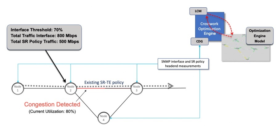
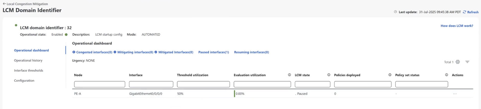
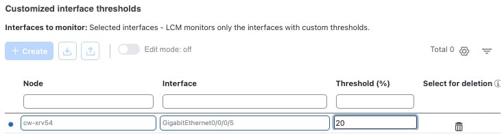
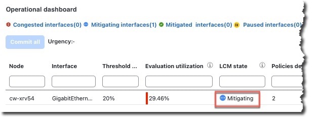
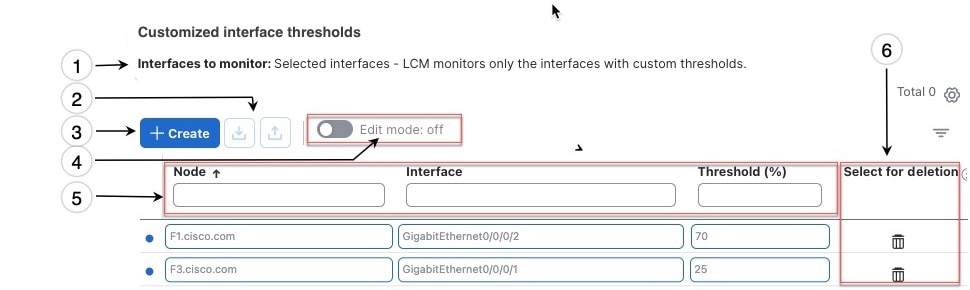
monitors congestion as defined by the interface thresholds you specify and detects congestion on a configurable cadence (as opposed to a triggered event) by monitoring interface utilization and traffic thresholds,
-
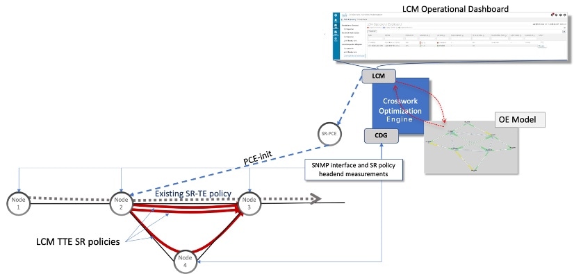
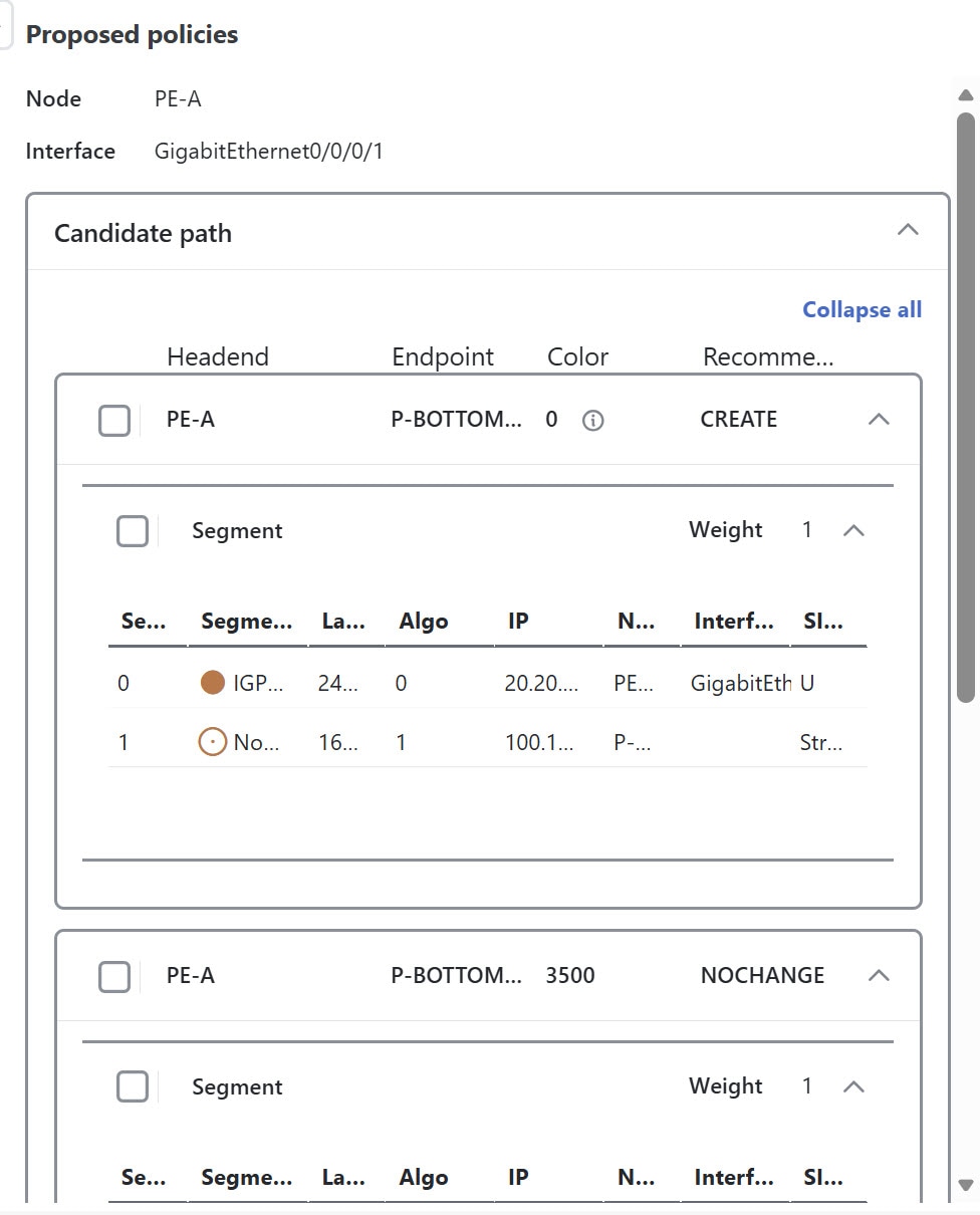
computes shortest paths for tactical policies to divert minimal traffic from congested interfaces to alternate paths with sufficient bandwidth,
-
aims to keep as much traffic as possible on the original IGP path while mitigating congestion,
-
provides localized mitigation recommendations in surrounding interfaces (local interface-level optimization) within a domain, eliminating the need to simulate edge-to-edge traffic flows in the network through a full traffic matrix,
-
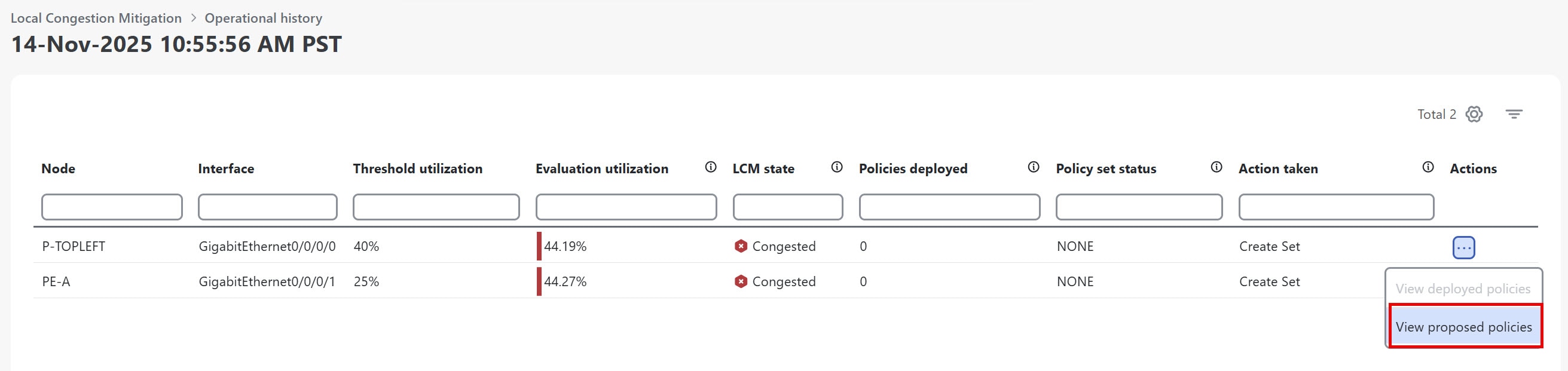
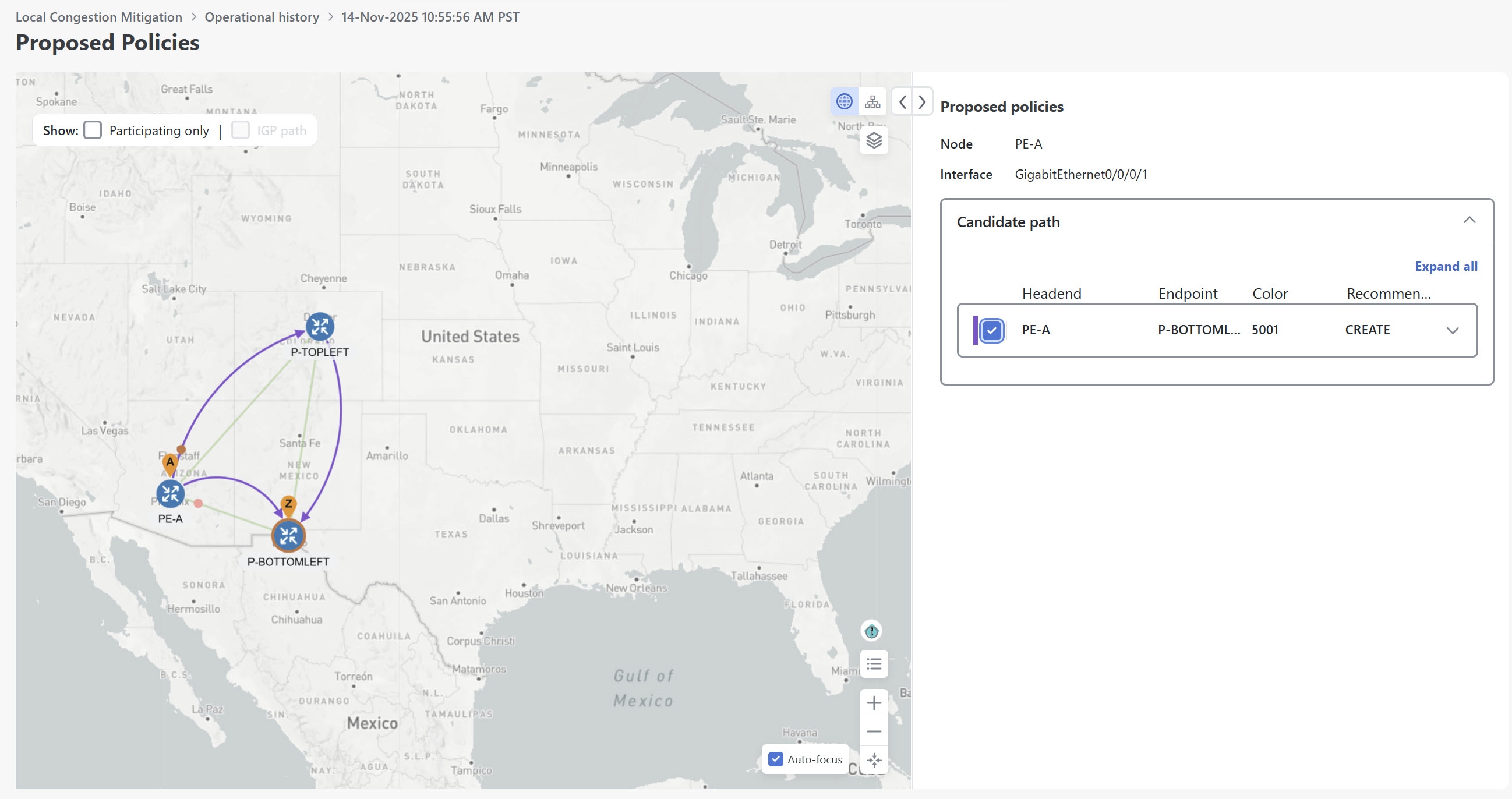
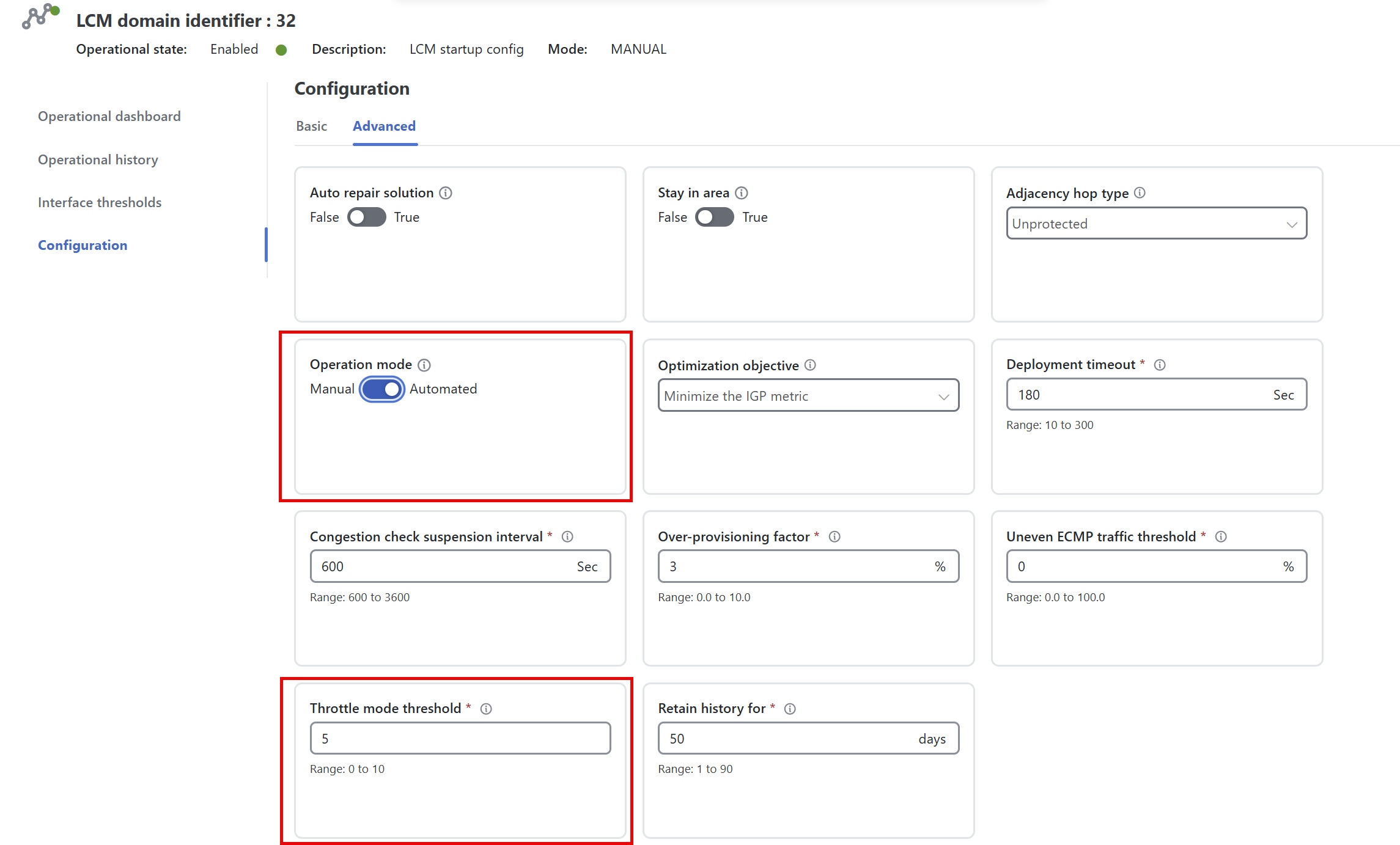
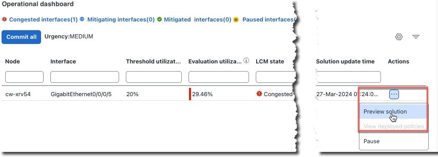
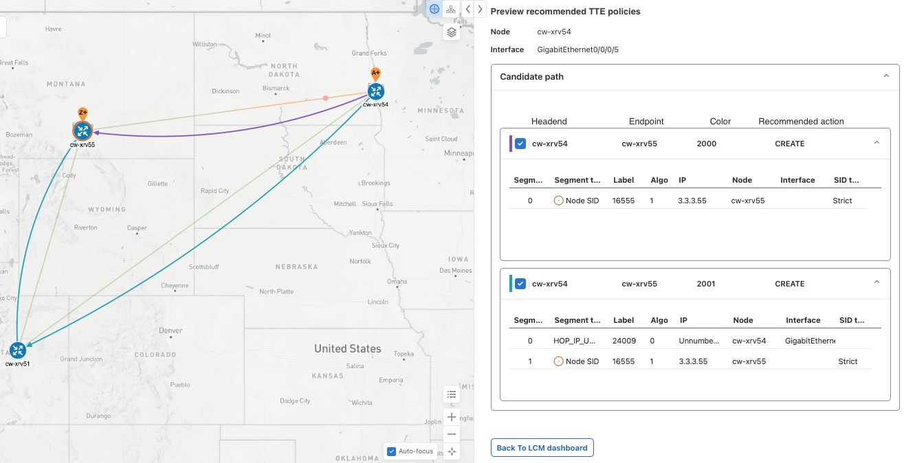
allows users to visually preview LCM recommendations before committing Tactical Traffic Engineering (TTE) SR policy deployments (feature available in Manual mode),
-
can automatically deploy Multiple Segment List (MSL) policies for devices that are fully gRPC MSL compliant based on specified thresholds (feature available in Automated mode),
-
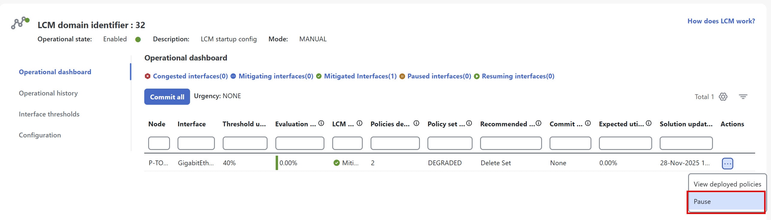
supports automatic deletion of down, failed, or uncommitted LCM TTE policies to reduce network failure risks (see Auto Repair Solution and Adjacency Hop Type) in LCM configuration options),
-
collects TTE- SR policy and interface counters via SNMP and does not require Segment Routing Traffic Matrix (SR-TM), and
-
is designed for scalability and applicability in large networks with multiple IGP areas, because of its simpler path computation and limitation to specific network elements.
Refer to Example: Mitigate congestion on local interfaces to see how to use LCM in your network.

 and then click
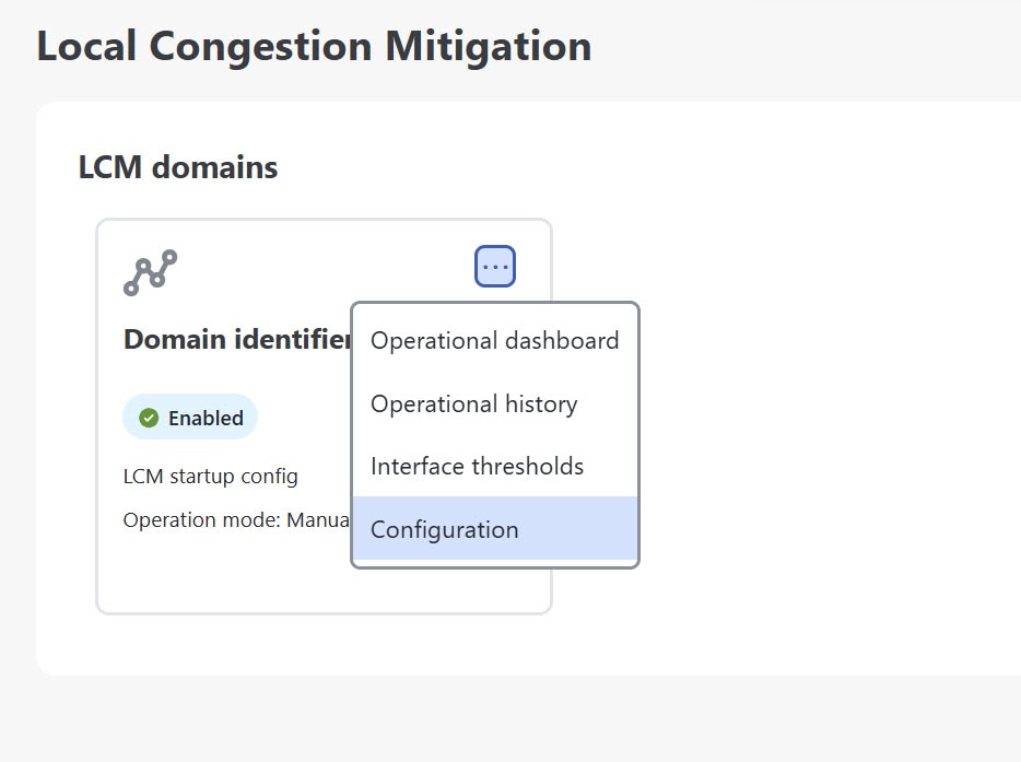
 Feedback