High-availability Seamless Redundancy
High-availability Seamless Redundancy overview
HSR is defined in International Standard IEC 62439-3-2016 clause 5. HSR is similar to Parallel Redundancy Protocol (PRP) but is designed to work in a ring topology. Instead of two parallel independent networks of any topology (LAN-A and LAN-B), HSR defines a ring with traffic in opposite directions. Port-A sends traffic counter clockwise in the ring, and Port-B sends traffic clockwise in the ring.
The HSR packet format is also different from PRP. To allow the switch to determine and discard duplicate packets, additional protocol specific information is sent with the data frame. For PRP, this is sent as part of a trailer called the redundancy control trailer (RCT), whereas for HSR this is sent as part of the header called the HSR header. Both the RCT and HSR header contain a sequence number, which is the primary data used to determine if the received frame is the first instance or a duplicate instance.
In this release, the switch supports only HSR-singly attached node (SAN) and only one HSR instance. If you have created a PRP instance, no HSR instance can be created.
The non-switching nodes with two interfaces attached to the HSR ring are referred to as Doubly Attached Nodes implementing HSR (DANHs). Similar to PRP, Singly Attached Nodes (SANs) are attached to the HSR ring through a device called a RedBox (Redundancy Box). The RedBox acts as a DANH for all traffic for which it is the source or the destination. The switch implements RedBox functionality using Gigabit Ethernet port connections to the HSR ring.
The following figure shows an example of an HSR ring as described in IEC 62439-3.
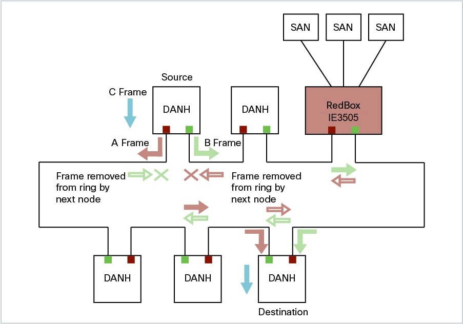
Devices that do not support HSR out of the box (for example, laptops and printers) cannot be attached to the HSR ring directly because all HSR capable devices must be able to process the HSR header on packets received from the ring and add the HSR header to all packets sent into the ring. These nodes are attached to the HSR ring through a RedBox. As shown in the figure above, the RedBox has two ports on the DANH side. Non-HSR SAN devices are attached to the upstream switch ports. The RedBox generates the supervision frames on behalf of these devices so that they are seen as DANH devices on the ring. Because the RedBox emulates these as DANH, they are called Virtual Doubly Attached Nodes (VDAN).
Switches that Support HSR
|
Switch |
PID |
|---|---|
|
Cisco IE3505 Rugged Series Switch |
IE-3505-8P3S |
|
IE-3505-8T3S |
|
|
Cisco IE3505 Heavy-Duty Series Switch |
IE-3505H-16T |
Support for HSR is available on Network Essentials and Network Advantage licenses.
Supported HSR Features
IE-3505-8P3S, IE-3505-8T3S, and IE-3505H-16T switches support the following HSR features.
Maximum of one HSR ring is supported as shown in the following table:
|
Switch |
FPGA Profile |
Number of Rings |
|---|---|---|
|
Cisco IE3505 Rugged Series without expansion module |
Default |
1 |
|
Redundancy |
1 |
|
|
Cisco IE3505 Rugged Series with expansion module |
Default |
1 |
|
Redundancy |
1 |
|
|
IE-3505H-16T |
Default |
1 |
|
Redundancy |
1 |
Loop Avoidance
Each node in the HSR ring forwards frames received from one port to the other port of the HSR pair. To avoid loops and use network bandwidth effectively, the RedBox does not transmit frames that are already transmitted in same direction. When a node injects a packet into the ring, the packet is handled as follows to avoid loops:
-
Unicast packet with destination inside the ring: When the unicast packet reaches the destination node, the packet is consumed by the respective node and is not forwarded.
-
Unicast packet with destination not inside the ring: Because this packet does not have a destination node in the ring, it is forwarded by every node in the ring until it reaches the originating node. Because every node has a record of the packet it sent, along with the direction in which it was sent, the originating node detects that packet has completed the loop and drops the packet.
-
Multicast packet: A multicast packet is forwarded by each node because there can be more than one consumer of this packet. For this reason a multicast packet always reaches the originating node. However, every node will check whether it has already forwarded the received packet through its outgoing interface. Once the packet reaches the originating node, the originating node determines that it already forwarded this packet and drops the packet instead of forwarding it again.
HSR RedBox Modes of Operation
The most basic mode of operation is HSR-SAN mode (single RedBox mode). In this mode, the RedBox is used to connect SAN devices to the HSR ring. The Redbox’s responsibility in this mode is to represent SAN devices as VDANs on the ring.
HSR SAN Mode
In HSR-SAN mode, the RedBox inserts the HSR tag on behalf of the host and forwards the ring traffic, except for frames sent by the node itself, duplicate frames, and frames for which the node is the unique destination. In this mode, packets are handled as follows:
-
A source DANH sends a frame passed from its upper layers (C frame), prefixes it with an HSR tag to identify frame duplicates, and sends the frame over each port (A frame and B frame).
-
A destination DANH receives two identical frames from each port within a certain interval. The destination DANH removes the HSR tag of the first frame before passing it to its upper layers and discards any duplicate.
-
Each node in the HSR ring forwards frames received from one port to the other port of the HSR pair. A node will not forward frames received on one port to the other under the following conditions:
-
The received frame returns to the originating node in the ring.
-
The frame is a unicast frame with a destination MAC address of a node upstream of the receiving node.
-
The node had already sent the same frame in the same direction. This rule prevents a frame from spinning in the ring in an infinite loop.
-
HSR-SAN interfaces
HSR-SAN mode is supported on interfaces GigabitEthernet 1/1-2 and GigabitEthernet 1/4-5. HSR ring 1 is configured as a pair of ports: Gi1/1 and Gi1/2 or Gi1/4 and Gi1/5.
|
Mode |
Module |
Port Interface |
|---|---|---|
|
HSR-SAN ring 1 |
Base Module |
GigabitEthernet1/1 and 1/2 or GigabitEthernet1/4 and 1/5 |
HSR-PRP (Dual RedBox Mode)
HSR-PRP mode, also called Dual RedBox mode, is used to bridge HSR and PRP networks. Dual RedBox mode is supported on the Cisco IE3505 Series Switch.
In this mode, two different RedBoxes connect to LAN A and LAN B of the PRP network. Two ports connect to the HSR ring and one port connects to one of the two PRP LANs. The traffic on the upstream interlink port connecting the RedBox to the PRP network is PRP-tagged. In HSR-PRP mode, the RedBox extracts data from the PRP frame and generates the HSR frame using this data, and performs the reverse in the opposite direction. To avoid loops and use network bandwidth effectively, the RedBox does not transmit frames already transmitted in same direction (see Loop Avoidance).
The following figure shows an HSR ring connected to a PRP network through two RedBoxes, one for each LAN. In this example, the source frame originates in the PRP network. RedBoxes are configured to support PRP traffic on the interlink ports and HSR traffic on the ring ports. Nodes connected to the HSR-PRP Redbox act as a SAN to the PRP Redbox and a VDAN to the HSR-PRP Dual Redbox.
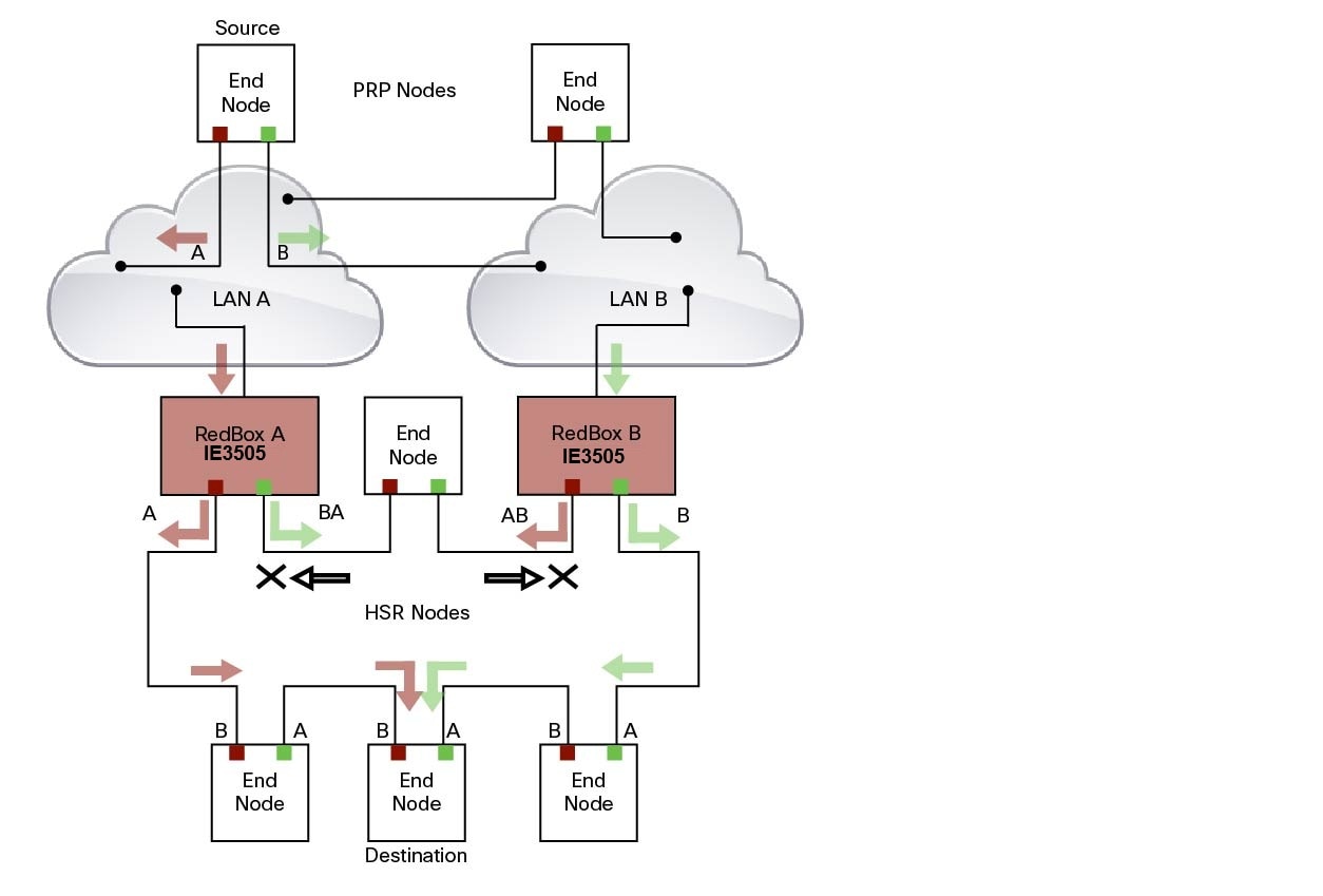
The sequence number from the PRP RCT is reused for the HSR tag and vice versa to allow frame identification from one redundancy network to the other and to identify the pairs and duplicates on either network. In the figure above, RedBox A and RedBox B send the same frame (A and AB and B and BA, respectively), but a RedBox does not transmit a frame that it already received.
Every DANH device generates its own sequence number, which is incremented for each outgoing frame. When a packet is switched from HSR to PRP or PRP to HSR, the sequence number is taken from the incoming packet so the same sequence number is used. Any node, whether it is an intermediate or final destination in the HSR or PRP network, uses the source MAC address and sequence number as the key for duplicate packet detection. Because the source address is expected to be unique for each node, there are no overlapping sequence numbers between different nodes.
Multicast frames or unicast frames without a receiver in the ring (arrows with the black outline in the figure) are removed by the RedBox that inserted them into the ring, if they originated from outside the ring. For this purpose, the frames carry a LAN identifier that is also the RedBox identifier.
The following figure shows an HSR ring coupled to a PRP network, where the source frame originates in the HSR ring.
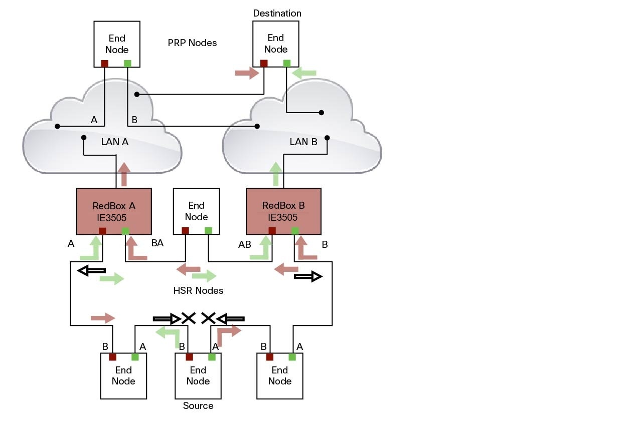
To prevent frames from being reinjected into the PRP network through the other RedBox, each HSR frame carries the 4-bit PathId, which identifies the PRP network from which the frame came originally. RedBoxes are configured and identified by the PathId of the PRP LAN to which they are attached.
Different PathIds can be used to bridge more than one PRP network to an HSR ring. Likewise, more than one HSR ring can be bridged to a PRP network.
PRP is not needed for HSR-PRP to function in the IE3500 Rugged Series Switches. Any third port can be connected to PRP LAN A or LAN B network without PRP or any specific configurations.
PRP Supervision frames are sent toward PRP LAN A or LAN B from conversion of HSR Supervision Frames originated from DANHs and VDANs of HSR RedBoxes in the HSR ring. The HSR-PRP Redbox does not generate them but passes them along.
Packet flow in HSR-PRP
Packets coming from PRP network in the coupled PRP LAN-A or LAN-B are expected to have an RCT (Redundancy Control Trailer) tag. The switch removes the RCT and transfers the information to the HSR header using the programmed Net ID and LAN ID, recalculates the CRC, and sends the modified packet out to both ring A and ring B. If the packets originate from a SAN in the coupled PRP network, the switch treats it similarly as a VDAN to the HSR ring.
Egress Data Path—Packets coming from a SAN or PRP LAN A or LAN B to the HSR ring:
-
For PRP packets, the switch converts the PRP RCT to an HSR tag for all packets (transfers Sequence Number and LAN ID from PRP to HSR).
-
For SAN packets, the switch just inserts the HSR tag as is done in HSR-SAN RedBox mode.
-
The switch needs to learn the MAC source address and add it to the Proxy Node table (VDAN table) with a new additional bit that allows the switch to distinguish between DANP or SAN. This allows the ingress path to determine whether to include the RCT trailer or not.
Ingress Data Path—Packets coming from the HSR ring to a SAN or PRP LAN A or LAN B:
-
If the Proxy Node table or VDAN table lookup of the MAC destination address returns DANP, the switch converts the HSR tag to PRP RCT for accepted packets (transfers Sequence Number and LAN ID from HSR to PRP RCT).
-
If the Proxy Node table or VDAN table lookup of the MAC destination address returns SAN, the switch strips the HSR tag and sends the packet without the RCT.
HSR-PRP Interfaces
In HSR-PRP Dual RedBox mode, two ports are connected to the HSR ring, and one port is connected to the PRP LAN A or LAN B network. The two ports that connect to the HSR ring are fixed (Gi1/1 and Gi1/2). When set to HSR-PRP mode, the two ports that connect to the HSR ring (Gi1/1 and Gi1/2) are automatically configured to HSR.
|
Mode |
Module |
Port Interface |
|---|---|---|
|
HSR-PRP |
Base Module |
GigabitEthernet1/1 and 1/2 |
The port connected to PRP LAN A or LAN B can be any other port from the base module or expansion module. All remaining ports of the HSR-PRP RedBox (base module or expansion module ports) can be used for any other purpose, for example, to connect a DHCP server.
These ports act as non-HSR/PRP nodes (SANs/VDANs) in the topology. The HSR-PRP RedBox can use all remaining ports (base module or expansion module ports) for other purposes, such as connecting a DHCP server. These non-PRP and non-HSR ports must be in the same VLAN as the HSR and PRP ports to achieve SAN/VDAN behavior.
Connecting Multiple PRP Networks to an HSR Ring
A maximum of six PRP networks, identified by the PathId, can be connected to the same HSR ring. The 4-bit PathId consists of the following:
-
The 3-bit NetId (1 to 6), which identifies a PRP network and the two RedBoxes that connect the PRP network to an HSR ring.
-
The 1-bit LanId (LAN A = 0 and LAN B = 1)
NetId values are as follows:
-
0 for regular HSR frames
-
1 to 6 for frames originating from a PRP network
-
7 is reserved
The following table lists the combinations of NetIds and LanIds for Redbox-A and Redbox-B.
|
PathId |
||
|---|---|---|
|
NetId |
LanId |
|
|
RedBox-A |
RedBox-B |
|
|
001 |
0 |
1 |
|
010 |
0 |
1 |
|
011 |
0 |
1 |
|
100 |
0 |
1 |
|
101 |
0 |
1 |
|
110 |
0 |
1 |
|
000 |
Used for Local HSR Ring |
|
|
111 |
Reserved |
|
The following figure shows an example of an HSR ring connected to two PRP networks.
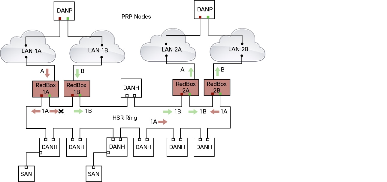
To prevent reinjection of frames coming from one PRP network into another PRP network or from the other LAN of the same PRP network, a RedBox only forwards frames that do not carry its own PathId from the HSR ring.
When a PRP frame from LAN A or from LAN B of a PRP network with a given NetId is inserted to the HSR ring, a RedBox inserts its own NetId and the LanId “A” or ”B” into the PathId of the HSR tag.
When forwarding a frame from the HSR ring to a PRP network, the RedBox inserts the LanId “A” or ”B” into the RCT.
Connecting Multiple HSR Rings to a PRP Network
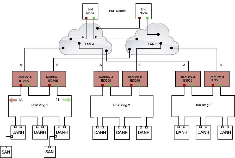
A PRP network can be connected to any number of HSR rings, but these rings cannot be connected to each other because this would create loops. The following figure shows an example of three HSR rings connected to one PRP LAN.
HSR Alarms
An HSR ring can generate the following two alarms:
-
Partial Ring Fault: This fault is generated by an HSR RedBox when one of its physical ring ports/links is down. Because the packets can be sent using the redundant path, this is considered as a partial fault. However, this fault still requires user intervention to restore the ring. This is a minor fault and cannot be associated with an external hardware alarm relay.
-
Full Ring Fault: This fault is generated by an HSR RedBox when both of its physical ring ports/links are down. This is a catastrophic failure and needs immediate attention. This is a major fault and can be associated with an external hardware alarm relay.
When an event that raises an alarm is generated, it can be associated with one or more of the following actions to notify the user:
-
Syslog: A syslog is generated when the Alarm is raised/cleared.
-
SNMP Notification: SNMP notification is sent when the alarm is raised/cleared.
-
Relay output: External relay contacts can be asserted/de-asserted in response to the alarm. Relays are activated by major faults only.
See Enabling HSR Alarms for steps to configure HSR alarms.
The following table lists the HSR events and their representations.
|
Event Number |
Event Description |
System Log (Level) |
Alert/Alarm Log |
Alarm LED and Output relay |
|---|---|---|---|---|
|
1 |
Ring goes from UP to DOWN state. |
2 |
2 |
Major Alarm/Assert |
|
2 |
Ring goes from DOWN to UP state. |
6 |
6 |
De-assert |
|
3 |
One ring port goes DOWN, the other ring port and the ring itself is UP. |
3 |
3 |
|
|
4 |
Both ring ports are UP again. |
6 |
6 |
You can view currently active alarms using the show facility alarm status command. The following example shows alarm status for minor and major HSR alarms:
Switch#show facility-alarm status
Source          Severity    Description                      Relay   Time
Switch            MINOR    34 HSR ring is partially down        MAJ    Oct 24 2017 10:16:10
-------
Switch# show facility-alarm status
Source          Severity    Description                   Relay     Time
Switch            MAJOR    33 HSR ring is down               MAJ      Oct 24 2017 10:17:07
The following examples show the syslog entries that are generated for each HSR alarm event assertion and clear event (if configured):
-
Syslog generated on occurrence of Partial fault:
Oct 24 11:07:13.952 IST: %HSR_ALARM-3-HSR_PARTIALFAULT: The HSR ring in now in PARTIAL FAULT state -
Syslog generated when the Partial fault is cleared:
Oct 24 11:07:38.032 IST: %HSR_ALARM-3-HSR_PARTIALFAULT: The HSR ring in now in PARTIAL FAULT state - event cleared -
Syslog generated on occurrence of Full fault:
Oct 24 11:07:38.036 IST: %HSR_ALARM-2-HSR_RINGFAULT: The HSR ring in now in FAULT state -
Syslog generated when the Full fault is cleared:
Oct 24 11:08:19.082 IST: %HSR_ALARM-2-HSR_RINGFAULT: The HSR ring in now in FAULT state - event cleared
CDP and LLDP for HSR
HSR supports the Cisco Discovery Protocol (CDP) and Link Layer Discovery Protocol (LLDP). CDP and LLDP are Layer 2 neighbor discovery protocols. Both CDP and LLDP can provide information about nodes directly connected to the device. They also provide additional information such as the local and remote interface and device names.
When CDP or LLDP is enabled, you can use the CDP or LLDP information to find the adjacent nodes on an HSR ring and their status. You can then use the neighbor information from each node to determine the complete HSR network topology and debug and locate ring faults.
CDP and LLDP are configured on physical interfaces only.
For more information, see Configuring an HSR Ring and Verifying Configuration.
HSR Uplink Redundancy Enhancement
The HSR Uplink Redundancy Enhancement feature allows for flexible designs that enable two separate interfaces to connect upstream from the HSR ring through two separate HSR RedBoxes. This ensures there is no single point of failure exiting the HSR ring. Examples of protocols that can leverage this feature to improve high availability include HSRP, VRRP and REP. Prior to this enhancement, if these protocols were utilized on redundant uplinks, undesirable results could occur, such as next-hop split-brain conditions or slow REP failover times.
The following diagram shows an example network with HSR and HSRP that allows uplink next-hop gateway redundancy out of the HSR ring.
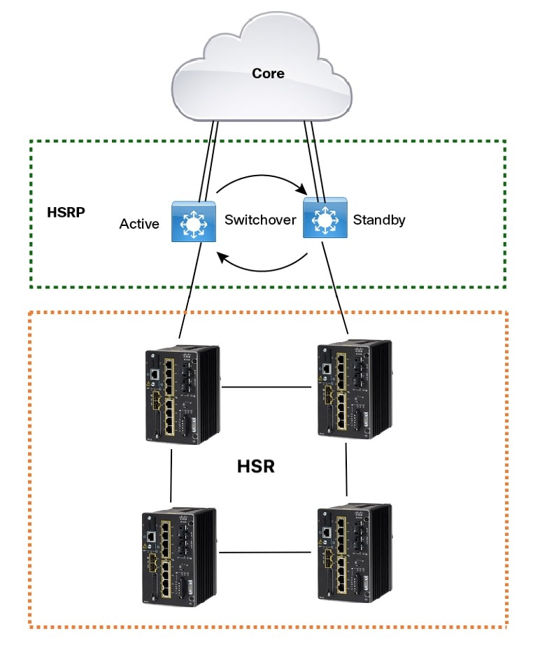
To implement HSR Uplink Redundancy, ensure that the fpgamode-DualUplinkEnhancement feature is not disabled. This feature is required to support the connectivity to a dual router (HSRP in this case) on the distribution layer:
Switch#show hsr ring 1 detail | include fpgamode
 fpgamode-DualUplinkEnhancement: Enabled
If the output shows fpgamode-DualUplinkEnhancement,:Disabled issue the following command:
Switch# conf t
Enter configuration commands, one per line.  End with CNTL/Z.
Switch(config)# hsr-ring 1 fpgamode-DualUplinkEnhancement
Switch(config)# end
HSRP Configuration
The following example HSRP configuration applies to the two distribution switches Active & Standby in the above figure. In the following configuration, HSRP is configured in a Switch Virtual Interface (SVI).
Active# conf t
Enter configuration commands, one per line.  End with CNTL/Z.
Active(config)# interface vlan 10
Active(config-if)# ip address 30.30.30.2 255.255.255.0
Active(config-if)# standby 1 ip 30.30.30.1
Active(config-if)# standby 1 priority 120
Active(config-if)# end

Standby# conf t
Enter configuration commands, one per line.  End with CNTL/Z.
Standby(config)# interface Vlan10
Standby(config-if)# ip address 30.30.30.4 255.255.255.0
Standby(config-if)# standby 1 ip 30.30.30.1
Standby(config-if)# end

Active# show standby
Vlan10 - Group 1
  State is Active
    8 state changes, last state change 00:03:55
    Track object 1 (unknown)
  Virtual IP address is 30.30.30.1
  Active virtual MAC address is 0000.0c07.ac01 (MAC In Use)
    Local virtual MAC address is 0000.0c07.ac01 (v1 default)
  Hello time 200 msec, hold time 750 msec
    Next hello sent in 0.176 secs
  Preemption enabled, delay min 5 secs, reload 5 secs, sync 5 secs
  Active router is local
  Standby router is 30.30.30.4, priority 100 (expires in 0.656 sec)
  Priority 120 (configured 120)
  Group name is "hsrp-Vl10-1" (default)
  FLAGS: 0/1
Active# show standby brief
                     P indicates configured to preempt.
                     |
Interface   Grp  Pri P State   Active          Standby         Virtual IP
Vl10        1    120 P Active  local           30.30.30.4      30.30.30.1


Standby# show standby
Vlan10 - Group 1
  State is Standby
    13 state changes, last state change 00:04:17
    Track object 1 (unknown)
  Virtual IP address is 30.30.30.1
  Active virtual MAC address is 0000.0c07.ac01 (MAC Not In Use)
    Local virtual MAC address is 0000.0c07.ac01 (v1 default)
  Hello time 200 msec, hold time 750 msec
    Next hello sent in 0.064 secs
  Preemption enabled, delay min 5 secs, reload 5 secs, sync 5 secs
  Active router is 30.30.30.2, priority 120 (expires in 0.816 sec)
  Standby router is local
  Priority 100 (default 100)
  Group name is "hsrp-Vl10-1" (default)
  FLAGS: 0/1
Standby# show standby brief
                     P indicates configured to preempt.
                     |
Interface   Grp  Pri P State   Active          Standby         Virtual IP
Vl10        1    100 P Standby 30.30.30.2      local           30.30.30.1

 Feedback