IRM-1100-4S8I Expansion Module Installation

This chapter describes the equipment, and the procedures necessary for successfully installing the Cisco IRM-1100-4S8I Expansion Module onto the IR1101.

For details on the expansion module, see Cisco IRM-1100-4S8I Expansion Module section.

Items shipped with your Expansion Module

Unpack the box and verify that all items listed on the invoice were shipped with the Cisco IRM-1100-4S8I.

The following items are shipped in the box:

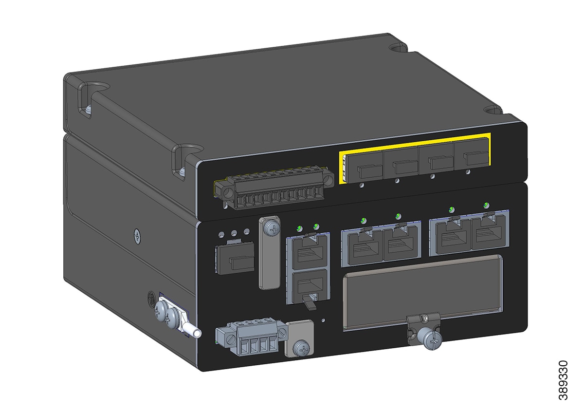
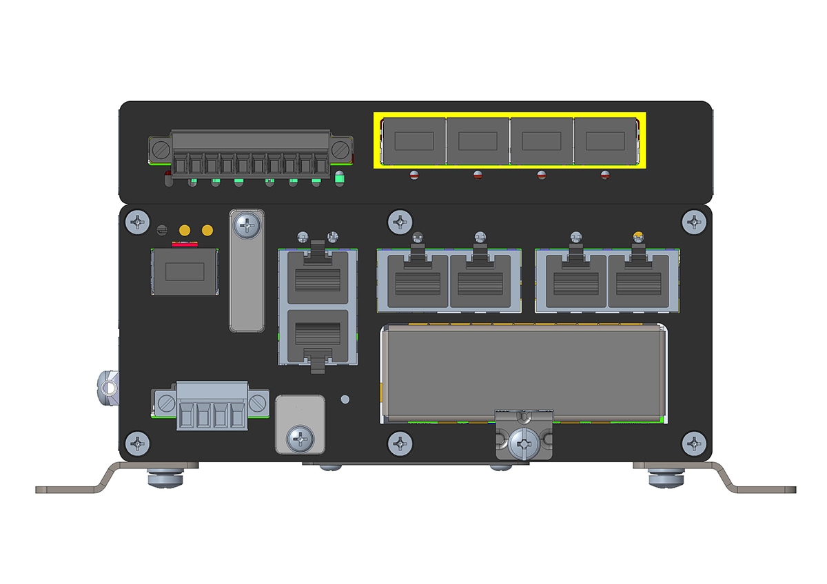
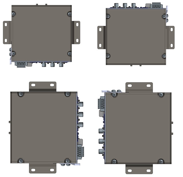
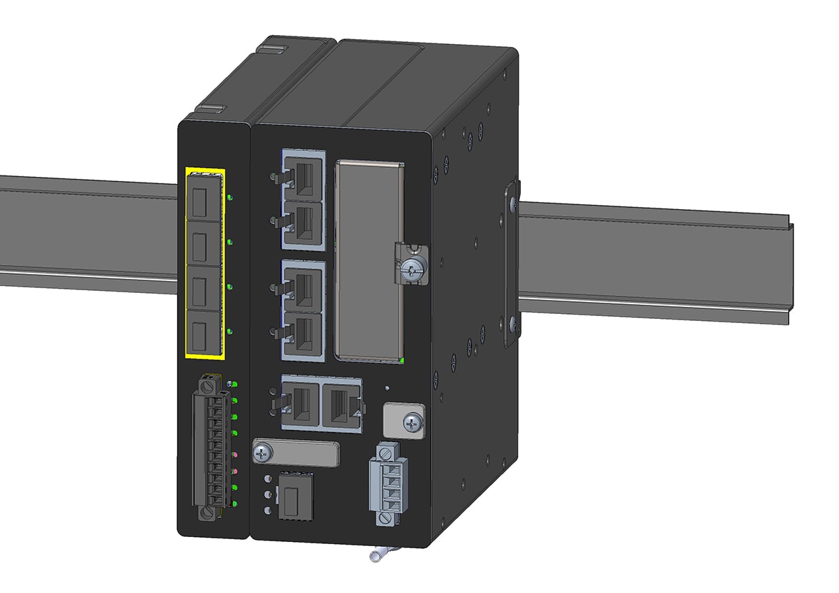
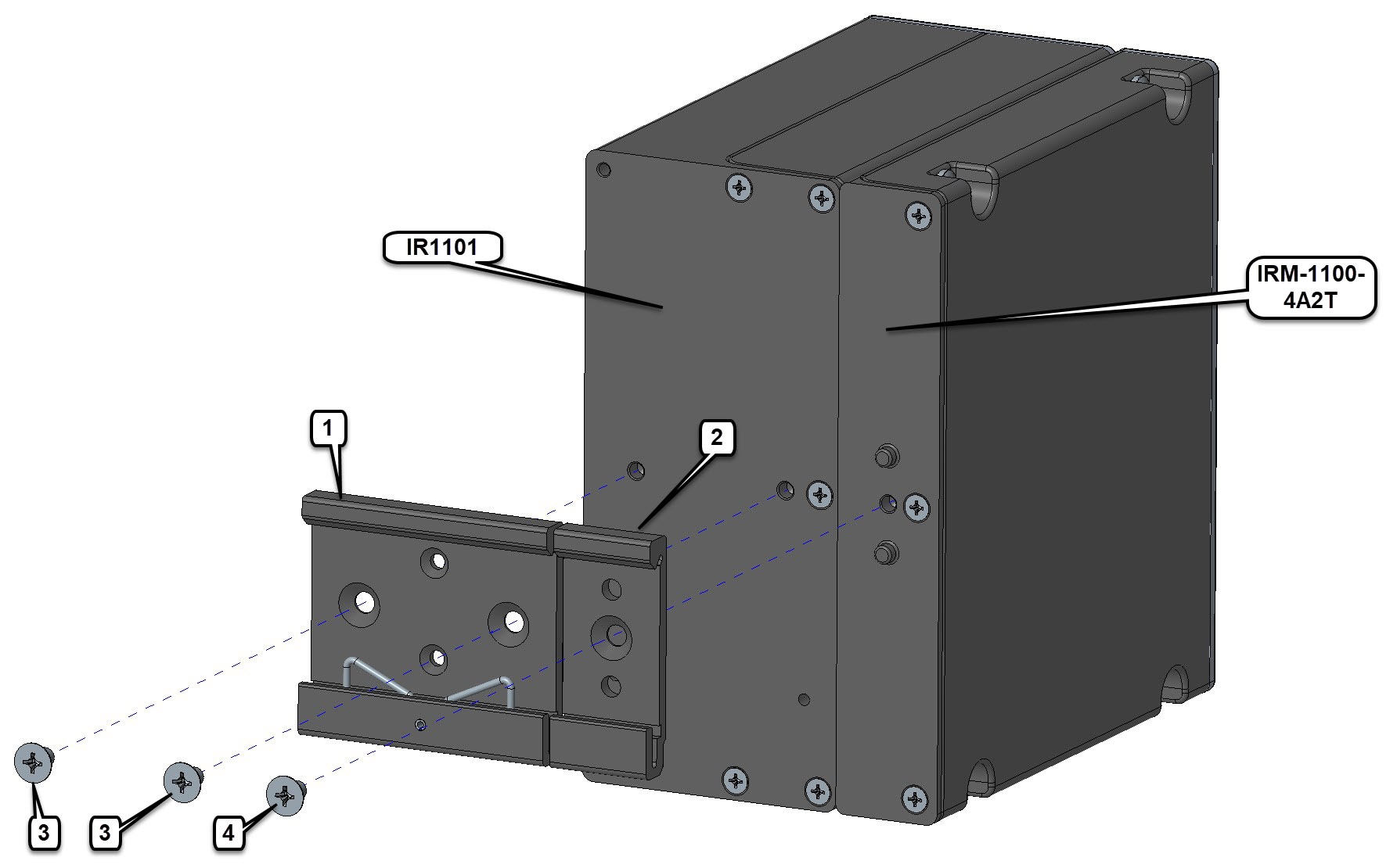
  • Cisco IRM-1100-4S8I expansion module

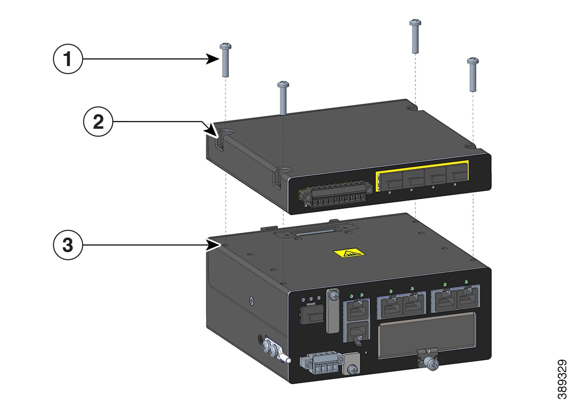
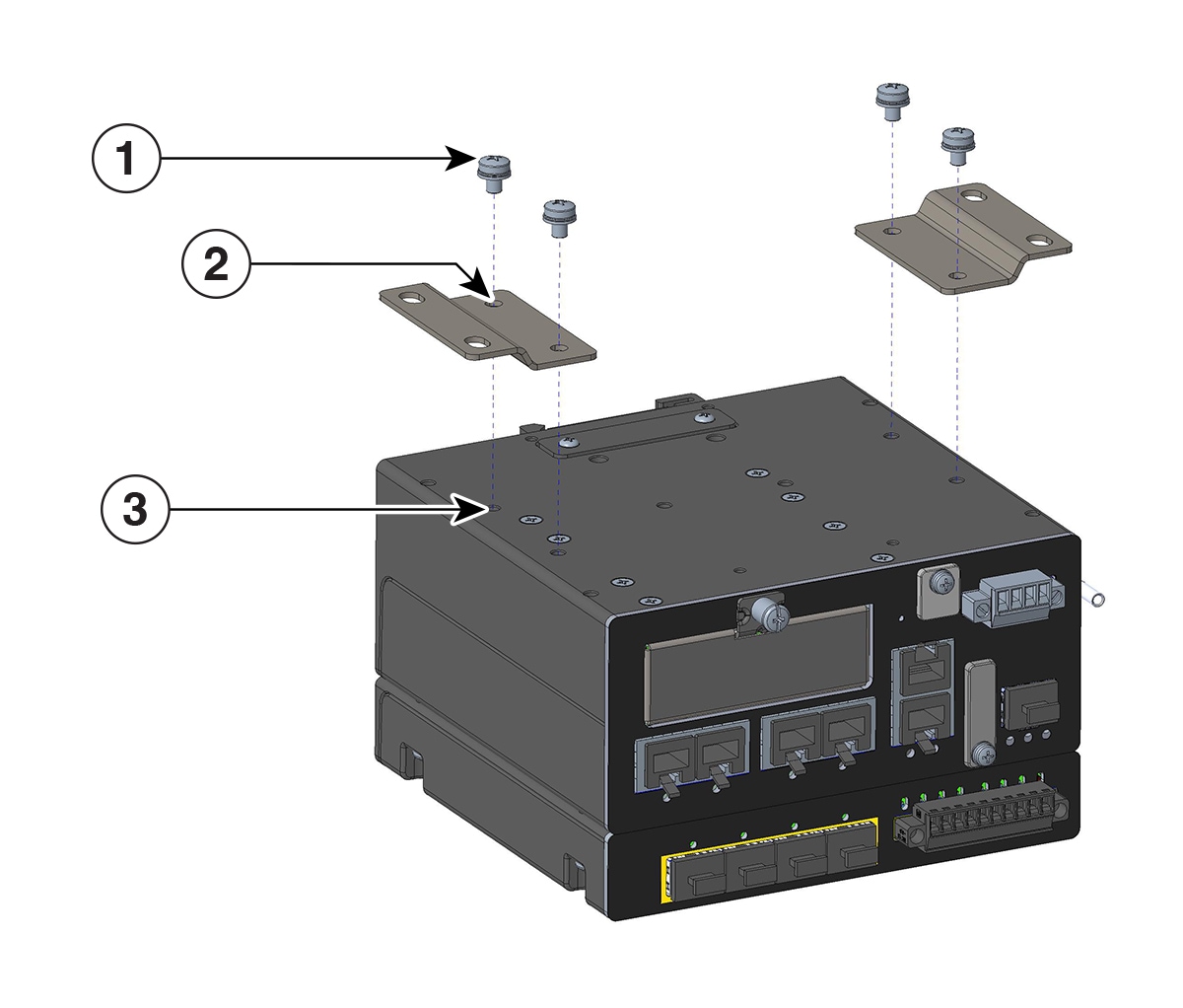
  • Four mating screws to connect the IRM-1100-4S8I to the IR1101

Installing the Expansion Module on the EM Side

This section describes how to install the Cisco IRM-1100-4S8I on the EM (top) side of the router. The Expansion Module is secured to the IR1101 Base with four Phillips head screws. It connects via a mating connector, which also provides grounding and power from the IR1101.

To attach the IRM-1100-4S8I to the IR1101 on the EM side, follow these steps.

Procedure


Step 1

Remove the protective cover from the mating connector on the IR1101 by unscrewing the two Phillips head screws.

Figure 1. Protective Cover

1

Phillips head screws

2

Protective cover

3

Cover mounting holes

Step 2

After removing the protective connector cover from the IR1101, carefully align the Expansion Module with the IR1101 so that the mating connectors engage. Once the Expansion Module is seated, secure it to the IR1101 with four mating screws.

Figure 2. Mounting the Expansion Module

1

Mating screws

2

Expansion mating screw holes

3

Mounting holes

Step 3

Tighten the screws to a torque of 13-15 in. lbs (1.5-1.7 Nm). When complete, the two devices form a single assembly.

Figure 3. Completed Assembly

Mounting the IR1101 Router with the IRM-1100-4S8I Expansion Module Attached

After the Cisco IRM-1100-4S8I module is attached to the IR1101, it can be mounted in the following ways:

  • On a DIN Rail

  • Using mounting brackets


Note


For the remainder of these instructions, we will refer to the combined IR1101/IRM-1100-4S8I as the “Device”.

Mounting the Device Using Mounting Brackets

The wall mounting kit part number is IR1101-WALLMNT and contains the following:

  • Mounting brackets (x2)

  • Mounting screws (x4)


Warning


Statement 1094—Read Wall-Mounting Instructions Before Installation

Read the wall-mounting instructions carefully before beginning installation. Failure to use the correct hardware or to follow the correct procedures could result in a hazardous situation to people and damage to the system.


Tip


When choosing a location for wall-mounting the Device, consider cable limitations and wall structure.

Note


A minimum of 1 inch clearance is required on all sides of the device except for the side mounted against the wall/floor or DIN rail, to allow for proper air flow.

The Device can be mounted on the top of a flat surface as shown in the following figure, but cannot be mounted upside down.

Figure 4. Table Mounting

The device can also be mounted vertically on a wall in four orientations as shown in the following figure.

Figure 5. Wall Mounting

To mount the Device on a wall or other flat surface, follow these steps:

Procedure


Step 1

Attach the mounting brackets to the bottom of the device.

Figure 6. Mounting Brackets

1

Provided screws

2

Holes in provided mounting brackets

3

Mounting holes

Step 2

Align the mounting brackets with the mounting holes, ensuring that the larger holes on the brackets extend beyond the edge of the device.

Step 3

Attach the brackets to the device using the four provided screws and a Phillips head driver. Tighten the screws to a torque of 13–15 in-lbs (1.5–1.7 Nm).

Step 4

Mount the device with the attached brackets to a suitable wall structure capable of supporting the combined weight of 3.85 lbs. Refer to the following figures for the mounting hole dimensions with the brackets attached.

Figure 7. Wall/Floor mounting hole dimensions with mounting brackets attached

Note

 
When mounting the device with the brackets attached to a surface, it is recommended to use four customer-provided #10-32 screws.
Figure 8. Wall/Floor mounting clearance and overall dimensions with mounting brackets attached

Step 5

Route the cables to avoid placing strain on the connectors or mounting hardware.


Installing a DIN Rail

The DIN rail kit is ordered separately (part number IRM-1100-DINRAIL). The device must be mounted vertically, with the ground lug positioned on the bottom.

Figure 9. Device Orientation

Mounting the DIN Rail Bracket on the Device

Procedure


Step 1

Attach the DIN rail brackets to the back of the device. There are two separate mounting brackets: one attaches to the IR1101, and the other attaches to the IRM-1100-4S8I. The combined DIN rail brackets mount in a vertical orientation only.

Figure 10. Attaching the DIN Rail Brackets

1

DIN mounting bracket

2

IRM-1100-DINRAIL mounting bracket

3

Screws from IR1101 kit

4

Screw from IRM-1100-DINRAIL kit

Step 2

Attach the DIN rail mounting bracket to the device using the two screws provided in the kit. Position the bracket over the two mounting holes, then tighten the screws to a torque of 13–15 in-lbs (1.5–1.7 Nm).

Step 3

Attach the IRM-1100-DINRAIL mounting bracket to the device using the screw provided in the kit. Position the bracket over the mounting hole, then tighten the screw to a torque of 13–15 in-lbs (1.5–1.7 Nm).

Step 4

Once the two brackets are attached to the device, you can mount it onto the DIN rail.


Attaching the Bracket Onto the DIN Rail

To attach the Device with the brackets to a DIN rail, follow these steps.

Figure 11. Attaching the Brackets to the DIN Rail

1

DIN rail clips

2

DIN rail

Procedure


Step 1

Position the router so that the lower edge and spring of the DIN clip, located within the bottom of the DIN rail bracket, engages with the bottom section of the DIN rail. Push up to compress the spring.

Step 2

Rotate the router so that the top hook of the DIN clip clamps to the top section of DIN rail.

Step 3

To remove the device from the DIN Rail, simply reverse the procedure.

Note

 
To prevent excessive side-to-side movement of the unit, install DIN rail stop plates such as Mouser part numbers 653-PFP-M, 651-1201662, or 845-CA402. These stop plates can be installed on one or both sides of the unit to limit movement, especially in high-vibration environments.

What to do next

After you install and properly ground the device, you can connect the power wiring, LAN cables, and administrative access cables as required for your installation.