Install and Configure NFVIS-for-UC
Available Languages
Contents
Introduction
This document describes NFVIS-for-UC installation, configuration, TAC best practices, app deployment, and migration from VMware ESXi environments.
Prerequisites
- Supported Business Edition or Cisco Expressway hardware that supports NFVIS-for-UC
- Business Edition 6000/7000 M5 or later
- Cisco Expressway C1400V M7
- NFVIS-for-UC version 4.18.2a
- Understanding of the NFVIS-for-UC architecture
- Collaboration Applications install media (OVA/ISO/.tar.gz) that support NFVIS-for-UC
The information in this document was created from the devices in a specific lab environment. All of the devices used in this document started with a cleared (default) configuration. If your network is live, ensure that you understand the potential impact of any command.
Background
Enterprise Network Function Virtualization Infrastructure Software for Unified Communications (NFVIS-for-UC) is built on the Enterprise NFVIS platform from Cisco, which was originally designed for branch office network function virtualization. Because of this heritage, the default network configuration uses branch-office naming conventions that do not map intuitively to all the Collaboration applications deployed on the platform. The network constructs show up as Bridges and Networks as part of Open vSwitch which is used by default for NFVIS-for-UC network. The default names are: wan-br (WAN Bridge), lan-br (LAN Bridge) and wan-net (WAN network) and lan-net (LAN Network). Depending on the appliance model, NFVIS-for-UC can map different physical NICs to these bridge interfaces. In terms of functionality, the Bridges are similar to vSwitches in VMware ESXi; they connect VMs to your upstream network infrastructure through a physical NIC (pnics—vmnics in ESXi). The Networks are similar to port groups in VMware ESXi, to which VMs are assigned on their virtual NIC, and they can provide a VLAN ID that tags traffic. If you are designing the NFVIS-for-UC network and need a starting point, refer to the example table which is the reference lab used in this document.
Similar to other hypervisors after NFVIS-for-UC is installed the next common step is to setup the management network, and VM networks to prepare the system for the Collaboration Apps. If you have previously installed ESXi and configured its virtual switches, you already have a strong foundation for understanding how NFVIS-for-UC networking functions. Because the network design of NFVIS-for-UC is similar to how ESXi functions, when migrating from ESXi to NFVIS-for-UC the existing network configuration can be reused, provided you do not intend to modify the current design. A BE7H-M5-K9 appliance is the hardare used as the example, as it is the first appliance that supports NFVIS-for-UC. While later versions of Business Edition and Cisco Expressway have updated hardware, the most notable difference during this setup process is the design of the CIMC interface and the NIC hardware, which changes how network ports appear in NFVIS-for-UC. For reference, we have outlined the BE7H-M5-K9 and BE7H-M7-K9 network ports.
BE7H-M5-K9
The BE7H-M5-K9 appliance is based on the Cisco UCS C240 M5SX platform and features these physical network interfaces:
- 1 Dedicated management port (RJ45)
- 2 10/1 GbE RJ45 motherboard ports via Intel X550
- 8 1GbE RJ45 ports via two Intel i350
See the UCS C240 M5 SFF Spec Sheet for more details and pictures.

Note: Note that the BE7H-M5-K9 has reached end-of-sale; see the End-of-Life announcement for migration options.
BE7H-M7-K9
The BE7H-M7-K9 appliance is based on the Cisco UCS C240 M7SX platform and features these physical network interfaces:
- 1 Dedicated management port (RJ45)
- 2 10/1 GbE RJ45 via OCP 3.0 NIC Intel-based X710-T2L
- 8 10GbE SFP+ via dual Intel-based X710-DA4
See the UCS C240 M7 SFF Spec Sheet for more details and pictures.
Appliance Port Usage Best Practices
Each port on the appliance can carry VM data traffic, NFVIS-for-UC management traffic, or both. Multiple ports can be bonded into an EtherChannel (port-channel) for link redundancy, as long as the uplink switches support it (for example, vPC). Link Layer Discovery Protocol (LLDP) can also be enabled to help verify physical connectivity between appliance ports and upstream switch ports during initial setup and troubleshooting. The recommended practice is (similar to what was done with VMware) to dedicate one port exclusively to NFVIS-for-UC management (SSH, Web UI, and API) and use the remaining ports for VM data traffic. Ideally, management and VM data traffic are be on separate VLANs and connected to different uplink switches, though this is not strictly required. The number of ports needed for VM data traffic depend on your design, the products deployed, and the expected scale.
Note: For 2 port BE models such as BE6K-M6-K9 and BE6K-M5-K9, implement network redundancy by isolating VM data and NFVIS-for-UC traffic into distinct VLANs, then aggregating both physical ports into a single Port Channel.
Reference Setup
| Usage | VLAN | IP | Gateway | pNIC | Bridge | Network | Uplink Switch Name | Uplink Switch Port |
|---|---|---|---|---|---|---|---|---|
| Appliance OOB CIMC | 100 | 10.0.100.10/24 | 10.0.100.1/24 | CIMC Management | mgmt-switch | Eth1/1 | ||
| NFVIS-for-UC Management | 101 | 10.0.101.10/24 | 10.0.101.1/24 | GE0-0 | lan-br | lan-net | mgmt-switch | Eth1/10 |
| VM Data1 | 10 | N/A | 10.0.10.1/24 | GE1-0 | vm-br1 | vm-net-10 | vm-switch | Eth1/11 |
| VM Data2 | 20 | N/A | 10.0.20.1/24 | GE1-1 | vm-br2 | vm-net-20 | vm-switch | Eth1/12 |
Network Connectivity Options
NFVIS provides several ways for VMs to obtain network connectivity. The two options most applicable to Collaboration products are Open vSwitch and Single Root I/O Virtualization (SR-IOV). It is recommended to use Open vSwitch as the traffic flow with Open vSwitch (bridges and networks) mirrors how VMware ESXi networking is normally set up (vSwitch and portgroups with VLAN ID, with vmnic that is the uplink to network infrastructure), this is also the historical norm for most Collaboration deployments. While ESXi has also supported SR-IOV, it was not commonly used with Cisco Collaboration products and the configuration for it was not exposed as prominently. NFVIS-for-UC however does expose SR-IOV in the default configuration due to its origin as a network-focused hypervisor. For the remainder of this article, Open vSwitch with bridges and networks in NFVIS-for-UC is used.
NFVIS-for-UC Hypervisor Install
Overview
This section provides an overview of the process to install NFVIS-for-UC including the steps that are only required if your moving from ESXi to NFVIS-for-UC. There are two options to move your ESXi-based Collaboration workloads to NFVIS-for-UC, these work whether you are using the same BE/CE appliance hardware or have new hardware for NFVIS-for-UC.
- When on a Collaboration product version that supports NFVIS-for-UC already, backup userdata via DRS.
- When on a Collaboration product version that does not support NFVIS-for-UC and supports Dataexport & install using dataimport (for example, CUCM 12.5 SU5+).
ESXi to NFVIS-for-UC migration workflow is similar in both instances:
Step 1: Backup userdata via DRS or Dataexport.
Step 2: Check if hardware Serial Number (SN) in CCW-R and SUDI Base PID are ok (must support NFVIS-for-UC)
Step 3: Check latest NFVIS release notes for HUU/CIMC/BIOS compatibility, update as needed.
Step 4: Fresh install NFVIS-for-UC (This overwrites ESXi and any Collaboration products installed).
Step 5: First time setup of NFVIS-for-UC (for example, management networks and VM data networks).
Step 6: If SUDI Base PID was bad, such as RMA was done so PID no longer shows support PID, contact TAC to fix.
Step 7: Upload NFVIS Image & Profile for Collaboration product(s) in question.
Step 8: Collaboration product(s) VM deployment and install process based on having done Dataexport (Fresh Install with Data Import) or DRS backup from step #1.
Note: For green field deployments with no existing Collaboration Apps, you skip step 1 and step 8 is a fresh install of the Collaboration App(s) in question without Data Import or DRS backup(s) being used.
NFVIS-for-UC Install
This section focuses on the NFVIS-for-UC process. If using your existing hardware/migrating from a ESXi installation ensure the additional steps in the ESXi to NFVIS-for-UC migration workflow are followed that support migration of your collaboration workload from ESXi to NFVIS.
Step 1: Ensure hardware supports NFVIS-for-UC.
Step 2: Check NFVIS release notes for HUU/CIMC/BIOS, and update as required (even a new appliance can require updates depending on when it was built in the factory and when you are doing the install).
Step 3: Download NFVIS-for-UC ISO, this guide uses the first NFVIS-for-UC release, Cisco_NFVIS-4.18.2a-FC1.iso.
Note: This software is found in the same location as NFVIS under "Enterprise NFV Infrastructure Software".
Step 4: Download OVA and ISO files for Collaboration Applications you plan on using with NFVIS-for-UC. This guide uses Unified Communications Manager and Expressway covering two common ways Cisco Collaboration products installation files are provided, OVA + ISO and single tar.gz/OVA file that includes multiple profiles and the product image.
Step 5: Login to your BE/CE CIMC to review the hardware configuration and ensure it matches what is required for your Business Edition or Cisco Expressway appliance. At a minimum at least one volume built for NFVIS-for-UC to be installed on, for BE servers this is a RAID5 volume. The exact number of volumes that are present depends on the specific Business Edition or Cisco Expressway Appliance being used. The NFVIS-for-UC installer installs on the first volume seen, this happens automatically with no user selection.
Step 6: Ensure your NFVIS-for-UC installation medium is being done from a device that is physically close or has a high speed connection to the appliance. Any disruption of connectivity of the mounted ISO cause the installation to fail and/or hang indefinitely. Install times vary, it is expected to take between 30-120 minutes).
Step 7: Login to CIMC and mount the NFVIS-for-UC installation media. The exact location and look of where these buttons are difference based on BE/CE and CIMC version being used. The general flow is is outlined with screen shots from a BE7H-M5-K9.
BE7H-M5-K9 CIMC, Click on Launch vKVM

BE7H-M5-K9 vKVM, Activate Virtual Devices
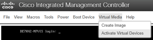
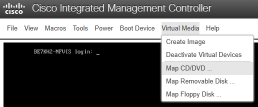
BE7H-M5-K9 vKVM, Virtual Media > Map CD/DVD to mount the NFVIS-for-UC installation media.
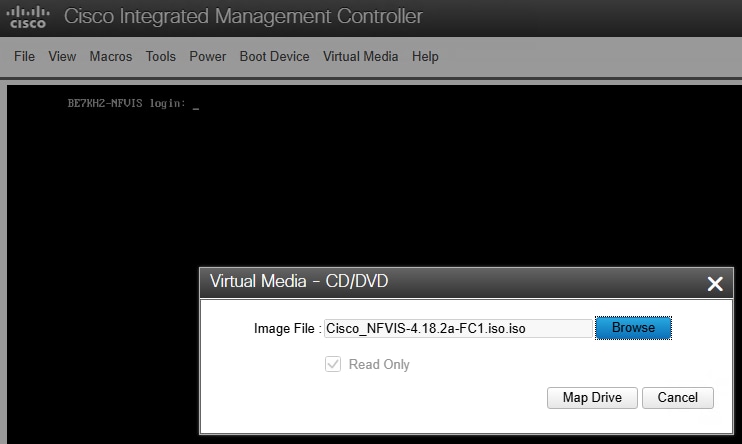
BE7H-M5-K9 vKVM, Browse to NFVIS-for-UC ISO location, then click Map Drive
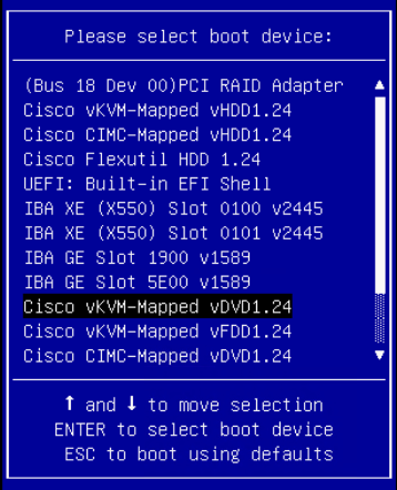
Step 8: Once the NFVIS-for-UC installation media is mapped, power cycle the appliance to boot off the ISO to start the installation. If needed explicitly tell the system to boot off the vKVM mapped DVD. This can be done by pressing F6 during the UCS boot process and selecting the Cisco vKVM-Mapped vDVD option selected.
BE7H-M5-K9 F6 Boot Options with Cisco vKVM-Mapped vDVD option selected.
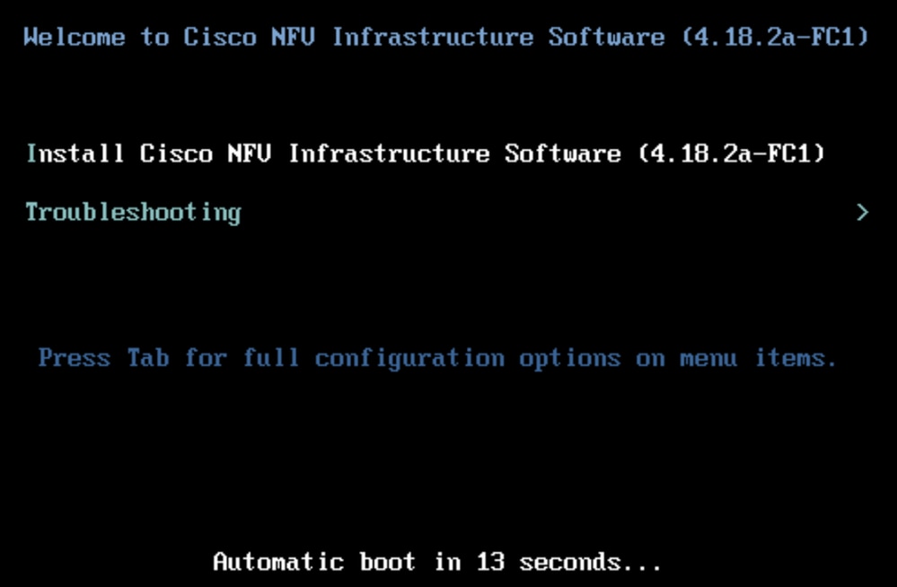
Step 9: When NFVIS-for-UC boots from ISO correctly the Welcome to Cisco NFV Infrastructure screen appears. Select Install Cisco NFV Infrastructure Software to proceed with installation.
Note: NFVIS-for-UC install can take 60-120 minutes, and the last screen (before reboot) can take 20-30 minutes to finish with no clear progress seen. Any disruption of connectivity of the mounted ISO can cause the install to fail and/or hang indefinitely.
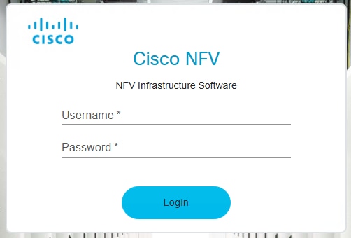
Step 10: After the NFVIS-for-UC is rebooted, login with default username and password. By design the system requires you to change the password.
- default username: admin
- default password: Admin123#
Step 11: Once NFVIS-for-UC is up the management network needs to be be setup to allow remote configuration and management via the WebUI, SSH and APIs. If this is your first time using NFVIS-for-UC there are a few helpful commands worth exploring at this point. A longer list of helpful commands is outlined at the end of this article. A few notable commands to run right after install are show version, show platform and show networks. This wil swho you show the default virtual networking setup right after install completion.
nfvis# show version
Cisco NFV Infrastructure Software
Version 4.18.2a-FC1
Build date Friday, January 16, 2026 [16:22:31 UTC]
Last Reboot Monday, June 10 [13:06]
nfvis# show platform
platform-detail hardware_info Manufacturer "Cisco Systems Inc"
platform-detail hardware_info PID BE7H-M5-K9
platform-detail hardware_info SN <Serial Number Omitted>
platform-detail hardware_info hardware-version 74-105773-01
platform-detail hardware_info UUID <UUID Omitted>
platform-detail hardware_info Version 4.18.2a-FC1
platform-detail hardware_info Compile_Time "Friday, January 16, 2026 [16:22:31 UTC]"
platform-detail hardware_info CPU_Information "Intel(R) Xeon(R) Gold 6132 CPU @ 2.60GHz 28 cores"
platform-detail hardware_info Memory_Information "196135372 kB"
platform-detail hardware_info Disk_Size "1495 GB"
platform-detail hardware_info CIMC_IP 10.0.100.10
platform-detail hardware_info Entity-Name ""
platform-detail hardware_info Entity-Desc ""
platform-detail hardware_info BIOS-Version C240M5.4.3.2g.0.0515250954
platform-detail hardware_info CIMC-Version 4.3(2.250045)
platform-detail software_packages Kernel_Version 4.18.0-513.18.2.el8_9.x86_64
platform-detail software_packages QEMU_Version 6.2.0
platform-detail software_packages LibVirt_Version 8.0.0
platform-detail software_packages OVS_Version 2.17.6
platform-detail switch_detail UUID NA
platform-detail switch_detail Type NA
platform-detail switch_detail Name NA
platform-detail switch_detail Ports 0
SFP
PCI TRANSCEIVER
NAME TYPE MEDIA LINK SPEED MTU MAC DETAIL TYPE
-------------------------------------------------------------------------------------------
GE0-0 physical Twisted Pair up 10000 9216 b0:8b:cf:10:b7:d2 01:00.0 NA
GE0-1 physical Twisted Pair up 10000 9216 b0:8b:cf:10:b7:d3 01:00.1 NA
GE1-0 physical Twisted Pair up 1000 9216 b4:96:91:2d:db:e8 19:00.0 NA
GE1-1 physical Twisted Pair up 1000 9216 b4:96:91:2d:db:e9 19:00.1 NA
GE1-2 physical Twisted Pair up 1000 9216 b4:96:91:2d:db:ea 19:00.2 NA
GE1-3 physical Twisted Pair up 1000 9216 b4:96:91:2d:db:eb 19:00.3 NA
GE2-0 physical Twisted Pair up 1000 9216 b4:96:91:2d:db:b8 5e:00.0 NA
GE2-1 physical Twisted Pair up 1000 9216 b4:96:91:2d:db:b9 5e:00.1 NA
GE2-2 physical Twisted Pair up 1000 9216 b4:96:91:2d:db:ba 5e:00.2 NA
GE2-3 physical Twisted Pair up 1000 9216 b4:96:91:2d:db:bb 5e:00.3 NA

nfvis#
nfvis# show networks
DEPLOYMENT DEPLOYMENT
NAME EXISTS NAME NIC ID
-----------------------------------------------
wan-net true
lan-net true
GE1-0-SRIOV-1 true
... Omitted default SRIOV networks ...
nfvis#
NFVIS-for-UC Remote Management Configuration
Before you can manage NFVIS-for-UC through the WebUI, SSH and APIs, you must assign it a management IP address from the CLI. Based on the hardware platform NFVIS-for-UC is installed on the bridge to physical NIC mapped could be different, the Reference Setup table is what is used in this example. For this lab GE0-0 is mapped to the wan-br bridge and as is the default configuration is be used for NFVIS-for-UC management. You can use either default bridge (lan-br or wan-br) and any port for management purposes. This is also a good time to review the full default configuration via show running-config, take particular note of the system settings, networks network, bridges bridge and pnic sections as these are the ones we modify during initial configuration.
Step 1: From the console, login and enter configuration mode via configuration terminal.
Step 2: Set system hostname, via system settings hostname hostname
Note: Saving a configuration change is done with the commit command, you can do this after each configuration or after several.
Step 3: Set management IP address, system settings mgmt ip address ip-address ip-subnet-mask
Step 4: Set default gateway, system settings default-gw ip-address
Step 5: Set source interface to originating traffic from NFVIS-for-UC, system settings source-interface ip-address
nfvis# configuration terminal
nfvis(config)# system settings hostname BE7KH2-NFVIS
nfvis(config)# commit
Commit complete.
BE7KH2-NFVIS(config)#
BE7KH2-NFVIS(config)# system settings mgmt ip address 10.0.101.10 255.255.255.0
BE7KH2-NFVIS(config)# system settings default-gw 10.0.101.1
BE7KH2-NFVIS(config)# system settings source-interface 10.0.101.10
BE7KH2-NFVIS(config)# commit
Commit complete.
BE7KH2-NFVIS(config)#
What the running configuration looks like at this point:
BE7KH2-NFVIS(config)# show running-config
!
... Omitted configuration to focus on management network setup ...
!
system settings hostname BE7KH2-NFVIS
system settings mgmt ip address 10.0.101.10 255.255.255.0
system settings default-gw 10.0.101.1
system settings source-interface 10.0.101.10
!
networks network wan-net
 bridge wan-br
!
networks network lan-net
 bridge lan-br
!
... Omitted configuration to focus on management network setup ...
!
bridges bridge wan-br
!
bridges bridge lan-br
 ip address 10.0.101.10 255.255.255.0
 port GE0-0
!
Note: If you need to change the physical port that is used for NFVIS-for-UC management the easiest way to do it is to modify the port configuration for the default bridge that is being used for management. In this lab the default bridge is lan-br and the default port is set to GE0-0.
Step 5b (Optional): Change the physical port used for NFVIS-for-UC management. If a different port needs to be used for NFVIS-for-UC management than the default simply change the port configuration in the default bridge used for management. In this example the default lan-br is using GE0-0 for management the process to change it to use port GE2-0 is:
BE7KH2-NFVIS# configure terminal
BE7KH2-NFVIS(config)# bridges bridge lan-br
BE7KH2-NFVIS(config-bridge-lan-br)# no port GE0-0
BE7KH2-NFVIS(config-bridge-lan-br)# port GE2-1
BE7KH2-NFVIS(config-port-GE2-1)# commit
Step 6: Upstream network configuration for the NFVIS-for-UC mangagement, this can optionally be done first. In this setup GE0-0 is being used for NFVIS-for-UC management and is directly connected to our management switch as an access port with the VLAN set on the port. The port configurationon this Nexus switch is:
interface Ethernet1/10
  description BE7KH2-NFVIS GE0-0 Mgmt
  switchport access vlan 100
Step 7: Once committed, verify connectivity. Connectivity can be verified by accessing the WebUI login screen at https://<NFVIS Management IP or FQDN>.
NFVIS-for-UC VM Network Configuration
Once you are able to remotely manage NFVIS-for-UC the next step is setting up networks for Virtual Machine connectivity. In this setup, GE1-0 and GE1-1 are used for VM data traffic.
Step 1: Login to NFVIS-for-UC WebUI at https://<NFVIS Management IP or FQDN> using credentials you set earlier.
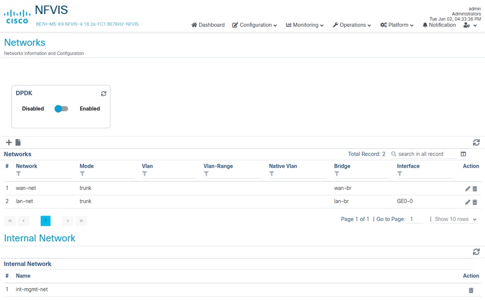
Step 2: Navigate to Network configuration page from drop Configuration > Virtual Machines > Networking > Networks

Networks page default configuration (BE7H-M5-K9)
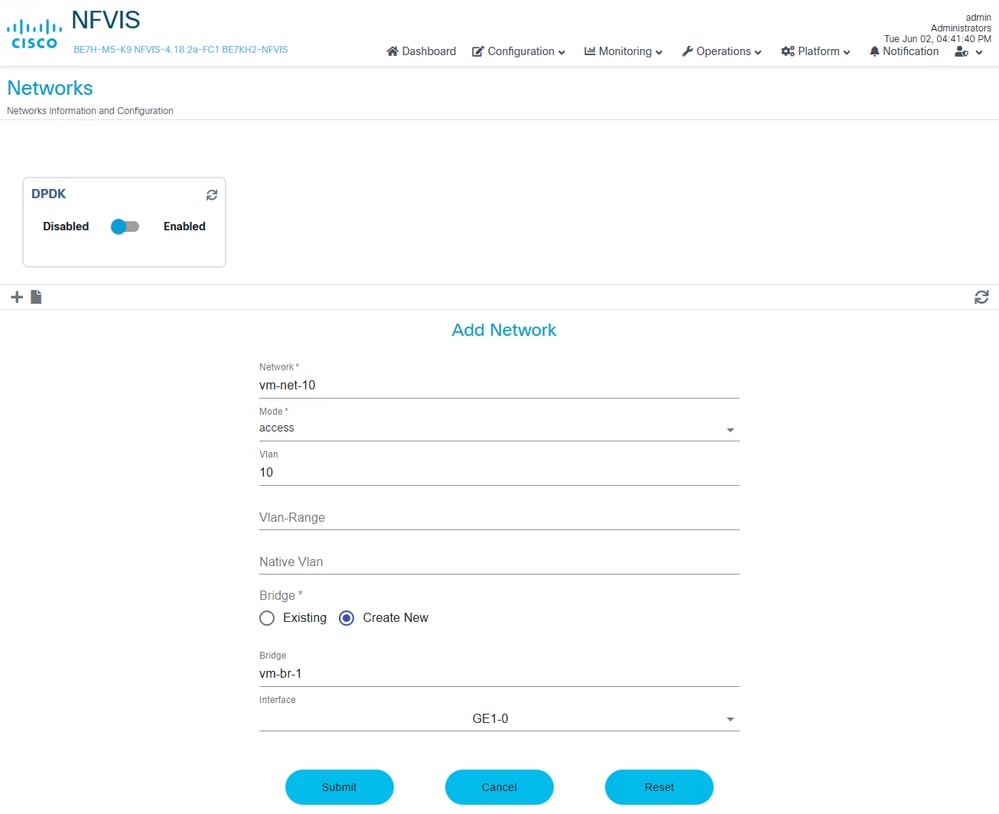
Step 3: Add New network, by clicking on the "+" sign to add network. Enter network details and click Submit once done and repeat the same step for other VLANs/network, re-use the same bridge or create a new one based on your design.
- Name: vm-net-10
- Mode: Access
- VLAN: 10
- Bridge: "create new", "GE1-0" as interface to use. Recall that GE0-0 is being used for NFVIS-for-UC management.
The networks now appear on the Networks page.
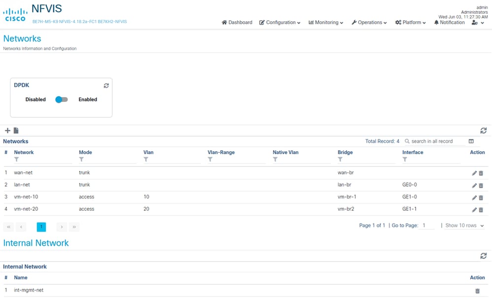
You can also see these networks created from the NFVIS-for-UC CLI.
BE7KH2-NFVIS# show system networks
NETWORK        BRIDGE   PORTS            TYPE         VLAN
----------------------------------------------------------
wan-net        wan-br   N/A              openvswitch  N/A
lan-net        lan-br   GE0-0,GE0-0_ll1  openvswitch  N/A
GE1-0-SRIOV-1  N/A      N/A              SRIOV        N/A
...omitted default SRIOV networks...
vm-net-10      vm-br1   GE1-0,vnic0      openvswitch  10
vm-net-20      vm-br2   GE1-1,vnic1      openvswitch  20

BE7KH2-NFVIS#
Collaboration Application Install
Collaboration application install requires several steps before the application can be installed. Similar to the NFVIS-for-UC installation it is recommended to do these steps from a system that is physically close to the appliance or has a high throughput network connection to the NFVIS-for-UC appliance as the images are often quite large. The general process of a Virtual Machine build in NFVIS-for-UC is a two steps:
1. Image Creation
2. Node (VM) deployment
The image creation process requires uploading the OVA, ISO or .tar.gz image package that is then be used for deploying a Virtual Machine of the specific Collaboration Application. The node deployment process includes setting the deployment details, such as a name, and network(s) to be connected, some of these can be different depending on the speicfic product. After deployment occurs the normal Collaboration application process occurs.
Image Creation
This section goes through two examples that covers the most common image creation process, OVA & ISO and a single file.
- UCM has 2 files that must be uploaded together; otherwise the deployment fails.
- cucm_15_all_esxi_vmv17_or_nfvis_v1.0.sha512.ova
- Bootable_UCSInstall_UCOS_15.0.1.14901-2.sha512.iso
- Cisco Expressway Series - X15.5 NFVIS version has a single file
- s42700x15_5_0_NFVIS.tar.gz
Expressway Eample
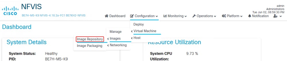
Step 1: From NFVIS-for-UC WebUI, Configuration > Virtual Machine > Images > Image Repository
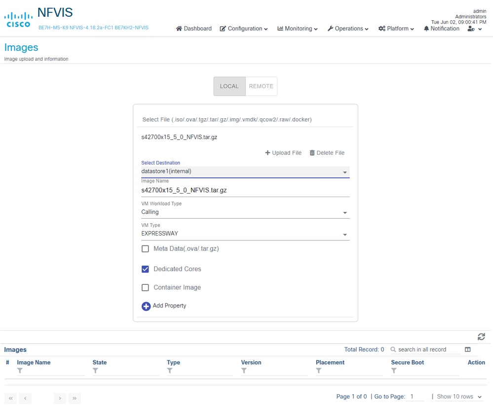
Step 2: Configure and upload the image.
- Click Select File, choose image of s42700x15_5_0_NFVIS.tar.gz
- Modify datastore as needed
- Give the image a name, example keeps default which is the name of the uploaded file.
- Change VM Type to EXPRESSWAY
- Check Dedicated Cores
- Click Upload File
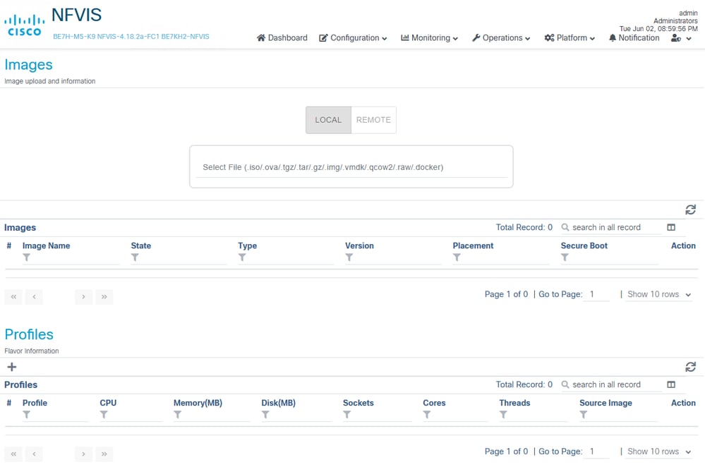
Image Repository with no images or profiles
Expressway image ready to upload
Expressway image uploading
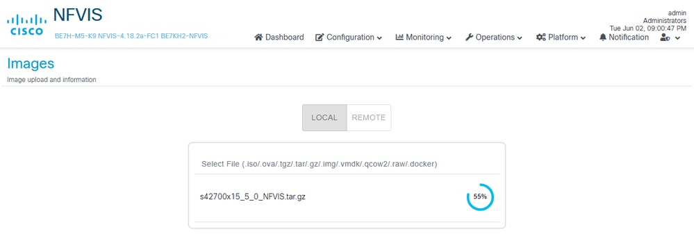
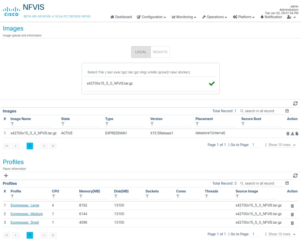
Step 3: When the upload is successful, the image plus 3 profiles created automatically show up - this takes a few minutes as the image is uploaded and the system processes them. Hitting the refresh button of the Images and Profiles sections could be required to see the latest Image and Profiles uploaded.
Expressway image uploaded with profiles present
UCM Example
UCM requires ISO image with OVA to be uploaded.
Step 1:From NFVIS-for-UC WebUI, Configuration > Virtual Machine > Images > Image Repository
Step 2: Configure and upload the image.
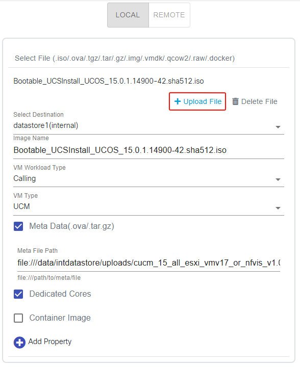
- Click Select File, choose the ISO file first, give the image a name or datastore if you prefer
- Modify datastore as needed
- Give the image a name, example keeps default which is the name of the uploaded file.
- Change VM Type to UCM
- Check Dedicated Cores
Step 3: Then check Meta Data box, after Meta Data box checked, an additional Select File option becomes available, click on it to choose the OVA file
CUCM image, Meta Data option selected
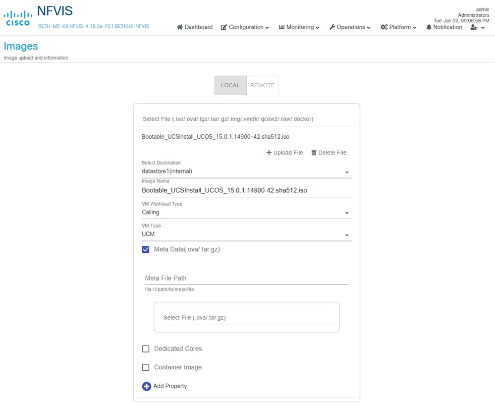
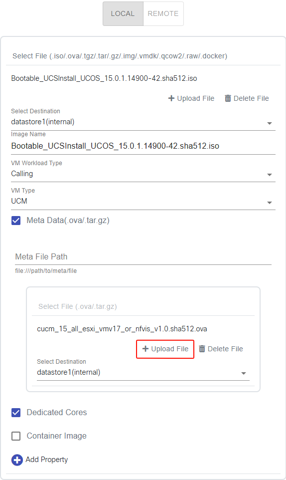
Step 4: Then click the 2nd Upload File to upload the OVA file.
CUCM image, metadata selected and ready to upload
Step 5: Then click the 1st Upload File to upload the ISO file.
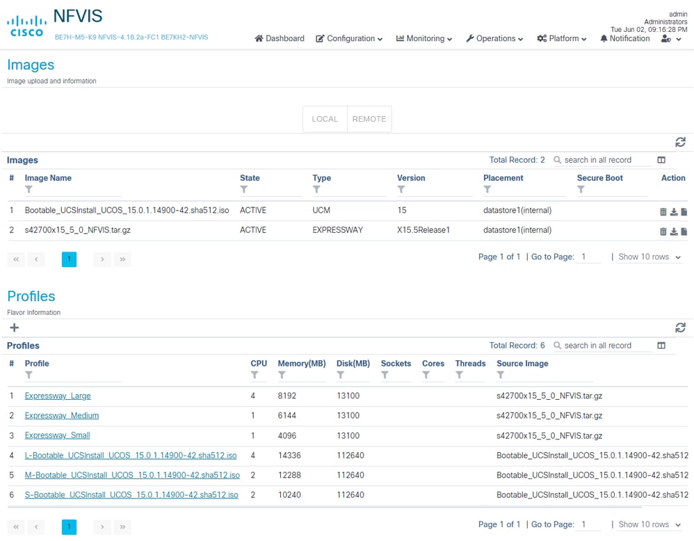
Step 6: Confirm the CUCM ISO image along with the profiles that are defined in the OVA show up on the Images page after a few minutes similar to Expressway.
Virtual Machine Deployment
Deploying Cisco UCM
Step 1: Navigate to the Deploy page to provision Virtual Machines.

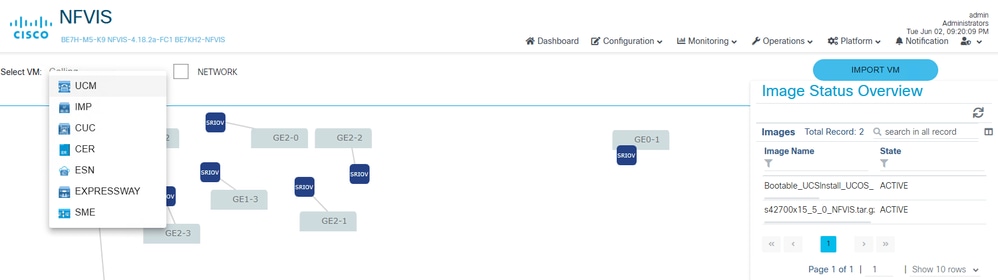
Step 2: To deploy a UCM VM, Select VM dropdown and select UCM
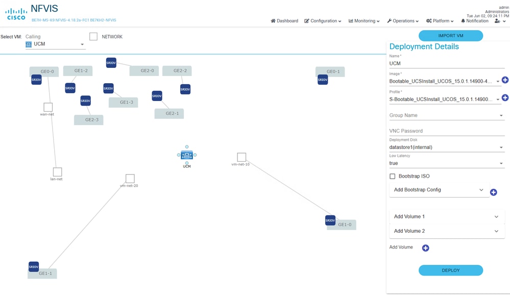
Step 3: A UCM VM node appears on the topology.
- Update the Name
- Select Desired Image
- Select Desired Profile
- Select Desired Deployment Disk
Step 4: Click on one of the blue circle souround the VM icon, drag the connection to the bridge you want to connect th VM too. You see a network shown with dotted line (not yet connected).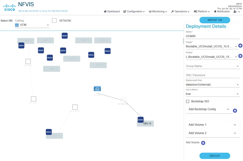
Step 5: Connect VM to desired network, when connected the dotted line becomes solid.
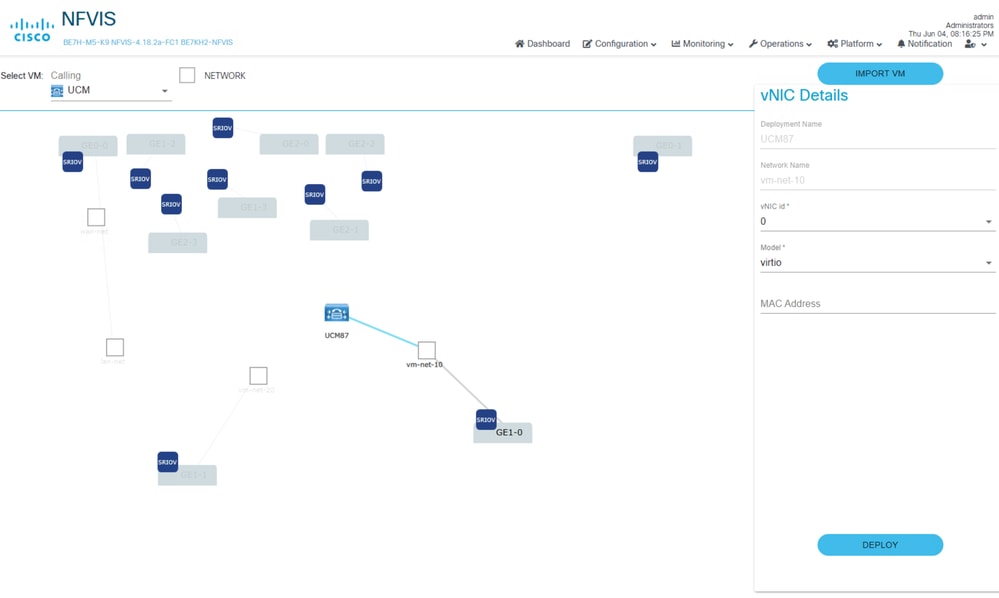
Step 6 (Optional): Use the same process deploy additional VMs as required. Use caution as a page refresh or navigating away from this page loses all configurations done prior to the Deploy button being clicked.
Step 7: Once VM has been configured, click Deploy. If multiple VMs have been configured, all of them get deployed.
Deploying Cisco Expressway
Step 1: Navigate to the Deploy page to provision Virtual Machines.
Step 2: To deploy a Expressway VM, Select VM dropdown and select EXPRESSWAY
Step 3: A EXPRESSWAY VM node appears on the topology.
- Update the Name
- Select Desired Image
- Select Desired Profile
- Select Desired Deployment Disk
- IP Address
- Mask
- Gateway
Step 4: Click on one of the blue circle souround the VM icon, drag the connection to the bridge you want to connect the VM too. Do this for each network connection.
Step 5: Once VM has been configured, click Deploy to deploy the VM.
Deploy Expressway, networks connected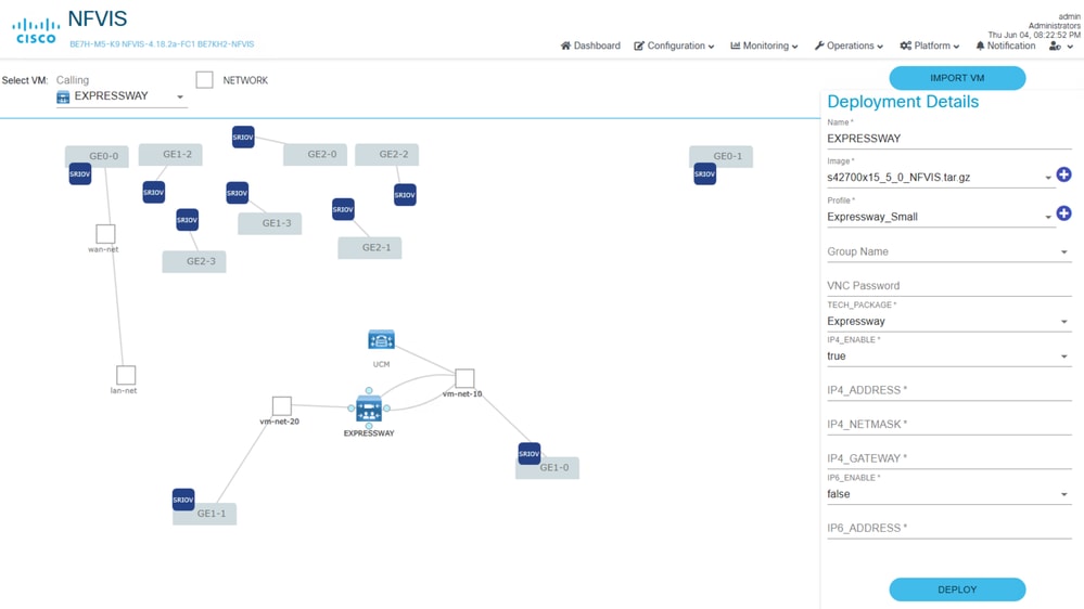
Deploy Expressway, configuration details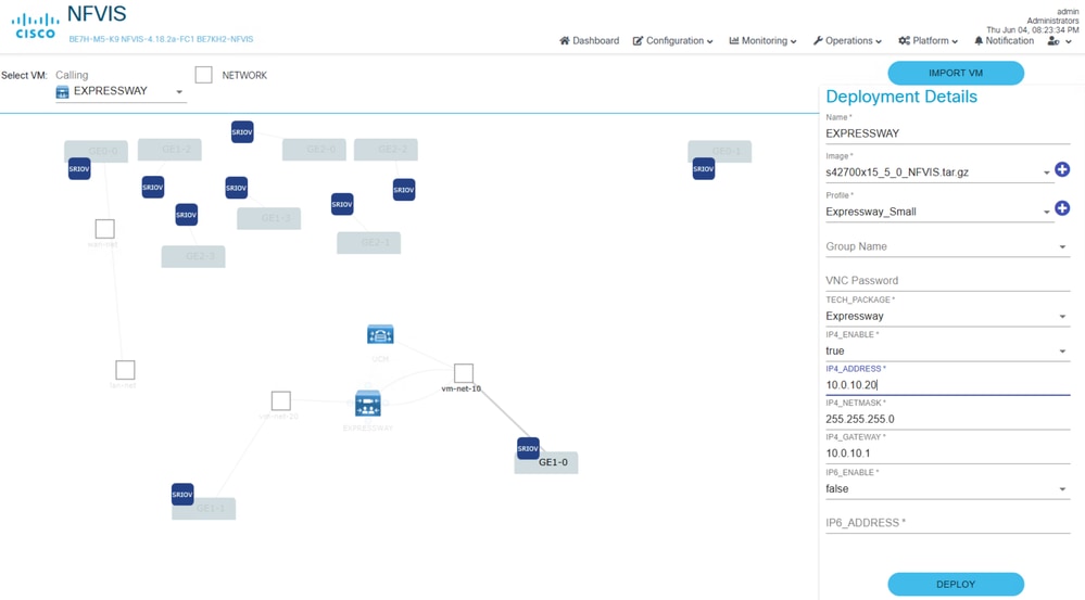
Manage Virtual Machines
Step 1: After the VM is created, they can be managed on the Configuration page. Configuration > Virtual Machine > Manage
Step 2 (Optional): On this page you can edit the networks of a Virtual Machine via the Action section pencil (edit) icon. Making changes to the connected networks here forces a Virtual Machine restart. You can also also see this network mapping for each deployed Virtual Machine from the CLI using the show networks command.
BE7KH2-NFVIS# show networks
                       DEPLOYMENT  DEPLOYMENT
NAME           EXISTS  NAME        NIC ID
-----------------------------------------------
wan-net        true
lan-net        true
GE1-0-SRIOV-1  true
...omitted default SRIOV networks...
vm-net-10      true    UCM         0
vm-net-20      true    EXPRESSWAY  0

BE7KH2-NFVIS#
Step 3: Access the Virtual machine consolevia the Action section >_ icon (Terminal).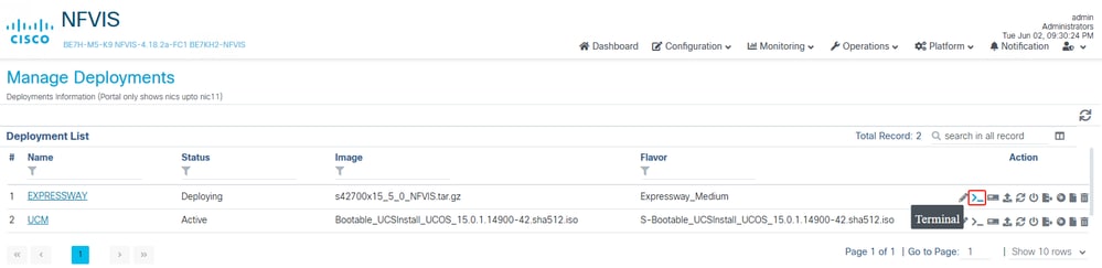
Step 4: Product specific installation procedures are now used to complete the install and configuration. For migrations this includes the data export or the DRS restore process that is applicaple for each Collaboration application being migrated.
Related Articles and Documentation
- CIsco Virtualization Guide for Cisco On-premises Calling Applications
- Cisco Business Edition 6000/7000 Appliances Installation Guide
- Understanding NFVIS Networking
- NFVIS 4.x Getting Started Guide
- NFVIS 4.x Configuration Guide
- Install NFVIS over CIMC Using Host
- Expressway Installation Guide
- CUCM installation Guide
- CUCM Data Export/Import Migration Method
- CUCM DRS Backup and Restore
Terminology Used
- BE6K/BE7K – Cisco Business Edition 6000/7000 series appliances, NFVIS-for-UC is supported on M5 or later
- CE1400V – Cisco Expressway appliance
- CIMC – Cisco Integrated Management Controller
- NFV – Network Function Virtualization, VNF can be considered as an outcome of NFV
- VNF – Virtualized Network Function (such as virtual router, firewall etc)
- NFVIS-for-UC – NFV Infrastructure Software for Unified Communications
- pNIC – Physical Network Interface Card, physically installed in the appliance, managed by NFVIS-for-UC
- vNIC – Virtual Network Interface Card, managed by NFVIS-for-UC, assign vNIC to virtual machines
- OCP NIC 3.0 – Open Compute Project Network Interface Card 3.0
- MLoM – Modular LAN on Motherboard
- OVS – Open Virtual Switch
- SR-IOV – Single Root I/O Virtualization, allows the pNIC to present itself to NFVIS-for-UC as multiple physical NICs
- DPDK – Data Plane Development Kit
Other Helpful Commands
Bridges are what allow us to connect VMs and NFVIS to the outside world, wan-br and lan-br are the default bridges.
show running-config bridges
show running-config bridges bridge wan-br
show running-config bridges bridge lan-br
show bridge-settings | more
Networks are what allow us to connect VMs to bridges, lan-net and wan-net are the default networks.
show running-config networks
show running-config networks network (tab to see all the options)
show running-config networks network lan-net
show running-config networks network wan-net
Other commands worth exploring.
show running configuration
show platform
show pnic
show nic
show system setting
show bridge-settings
show networks network
hostaction ?
show system status
show bridge-settings vlan
show lldp neighbors
show system networks
virsh commands
Revision History
| Revision | Publish Date | Comments |
|---|---|---|
1.0 |
25-Aug-2026
|
Initial Release |

 Feedback
Contact Cisco
- Open a Support Case

- (Requires a Cisco Service Contract)