25GE and 100GE – Enabling Higher Speeds in Enterprise with Investment Protection White Paper
Available Languages
Bias-Free Language
The documentation set for this product strives to use bias-free language. For the purposes of this documentation set, bias-free is defined as language that does not imply discrimination based on age, disability, gender, racial identity, ethnic identity, sexual orientation, socioeconomic status, and intersectionality. Exceptions may be present in the documentation due to language that is hardcoded in the user interfaces of the product software, language used based on RFP documentation, or language that is used by a referenced third-party product. Learn more about how Cisco is using Inclusive Language.

Unlock Smarter Workplaces: Start Your Cisco Spaces 30-Day Free Trial
Empower your hybrid workforce with intelligent, connected spaces and network insights.
Enterprise campus networks are facing an imminent need to support ever-increasing bandwidth demand. They need to support the rapid growth of powerful endpoints that can deliver richer content such as HD video and wireless access points that deliver advanced wireless connectivity technologies such as 802.11ax. To support the increase in connected devices and high data volumes moving toward the cloud, enterprises are looking for ways to minimize infrastructure upgrades that require substantial installation costs, time, and disruption to the physical infrastructure. Until recently, campus migrations have been from 1G to 10G to 40G. While 1G and 10G still represent a significant share of the enterprise market’s Ethernet ports, a transition to 25G, and to 100G for large and high-end enterprises, is expected to happen more quickly than the previous transition to 10G. Furthermore, support for 25G adapters that can also run at 10G with existing fiber cabling can help accelerate that migration, providing opportunities to migrate to a 100G switch infrastructure while supporting significant investment protection.
Cisco has been pioneering several initiatives to bring new Ethernet technologies to market. These include Cisco® 25GBASE Small Form-Factor Pluggable SFP28, Cisco 100GBASE Quad Small Form-Factor Pluggable QSFP28, and more importantly, dual-rate optics along with the latest Cisco Catalyst® 9000 switching family to facilitate such network speeds and architecture transformations. These innovations enable flexible options and backward compatibility to drive network speeds beyond the current 10G and 40G capabilities while minimizing cost and real estate changes. With a prevalidated architecture, Cisco’s Enterprise Networks portfolio can help forward-thinking enterprises that wish to build a network infrastructure that offers flexibility and scale. This white paper highlights some of the key aspects of these new Ethernet standards, and the benefits of 25G and 100G in campus networks. It also documents use cases involving high-speed network transitions that are extending link lengths for 25G to 300m over duplex Multi Mode Fiber (MMF) optical Mode 3(OM3) (400m over OM4) as well as provides details of supported Cisco’s platforms.
Need for a new Ethernet technology in campus networks
It is expected that IP traffic will grow at a Compound Annual Growth Rate (CAGR) of 24 percent from 2016 to 2021. More than ever, today’s enterprise networks need to support ubiquitous mobile applications, including HD multimedia video streaming, gaming, and social media communications. Mobile data traffic is projected to increase seven-fold from 2016 to 2021, (Figure 1). With increasing deployment of advanced wireless connectivity technologies, such as 802.11ac Wave 2 and 802.11ax, and powerful endpoints that handle high-volume data, network-access speeds are increasing from 1 Gbps to 2.5 Gbps, 5 Gbps, and potentially 10 Gbps.
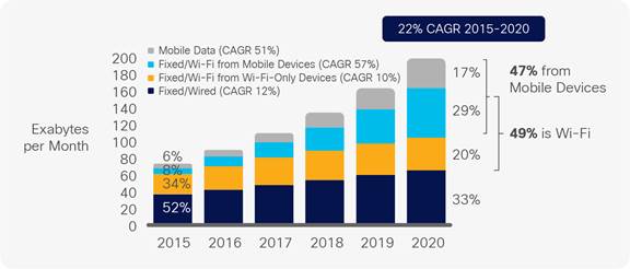
IP Traffic by Access Technologies, Cisco Networking index
To support 802.11ac Wave 2 wireless speeds, Cisco introduced Multigigabit Ethernet access layer switches offering speeds in the range from 100 Mbps to 10 Gbps. In near future, 802.11ax will make 5G the default connectivity between access point and switch. Applications such as 4K video, Virtual Reality (VR), and Augmented Reality (AR) will drive rapid adoption of 802.11ax. In addition, next-generation workstations are expected to come equipped with a 5G network interface controller. These new network access speeds and powerful endpoints have contributed to network upgrades requiring higher speeds than 10G. 40G, in the form of QSFP+, has been perceived as one of the migration options for speed upgrades from 10G. An additional option is to use multiple 10G links (port-channel or equal-cost multiple path).
10G to 40G migration in the enterprise
Moving to higher speeds can bring additional challenges. For instance, changing from an existing 10G to 40G link between access and distribution, or from a 40G to 100G link between the distribution and core layer, or adding additional10G or 40G uplinks, carries significant costs (transceivers and cables). In addition, achieving effective load sharing with multiple 10G links depends on the hashing technologies supported by switches.
40G technology for short reach over multimode fiber uses four lanes of 10G speed over parallel ribbon cable. With standard QSFP+ to SFP adapters and breakout cables, enterprises can support high-density 10G deployments. However, new cabling may be needed due to limited reach over standard multimode duplex fiber.
Backward compatibility is a key consideration for new speed adoption in campus networks. For instance, the availability of 10G SFP+ was the catalyst for widespread adoption of 10G. Besides the price premium for new modules, 10G X2/XFP presented a form factor conundrum. Although relatively late to the market, SFP+ optics’ form factor and backward compatibility with 1G SFP and 100-Mbps SFP has enabled that speed transition. Similar challenges of price premium for a new form factor and lack of backward compatibility pose challenges for widespread adoption of 40G. It is worth noting that in a 2017 report, Dell’Oro forecasted that the industry, including data center and campus, will be heading to 25G and 100G technologies instead of 40G (Figure 2).
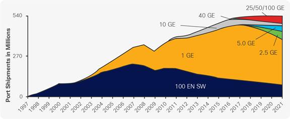
LAN Port Shipments — Dell’Oro report, July 17
Some practical considerations for choosing a network speed
In addition to cost and compatibility factors, when considering options for network upgrades, it is important to ensure that the new Ethernet technologies support:
● Investment protection: Dual-rate optics that enable cost-effective enterprise network equipment upgrades while minimizing real estate changes.
● Longer-reach connectivity: Campus-optimized distances with existing Multimode Fiber OM3/OM4 cabling standards. 40G bidirectional optics is optimized for multimode duplex fiber but offers a reach of only 100 m, while 10G Short-Range (SR) optics, a popular optics in enterprise, has a reach of 300 m but limited bandwidth.
● Higher-port-density architectures: Ethernet connectivity that offers a significant increase in bandwidth and port density and gradual network upgrades while maintaining backward compatibility.
Based on this Dell’Oro report,1 25G is expected to outgrow 10G by 2021. Enterprises that are contemplating network upgrades beyond 10G without creating bottlenecks must consider 25G as a natural successor to 10G, for reasons discussed in the following sections.
25G and 100G – optimized high-speed technologies
25G in the SFP28 form factor:
● Delivers 2.5 times more performance and bandwidth compared to existing 10G speeds.
● Supports technology advancements from 10G in packaging and silicon.
These benefits allow existing switch architectures to support link speeds faster than 10G with no increase in cable/trace interconnect, while keeping pace with the growth trajectory of networking bandwidth becoming faster and richer. Some benefits of the 25G IEEE standards include:
● Reduced CapEx through the reuse of existing cabling while still achieving higher bandwidths.
● Single-lane serial optics, providing a port density similar to that of 10G switches.
● Gradual migration options with the support of Cisco dual-rate optics.
● Reduced OpEx through savings in power and cooling.
● Campus-optimized distance with 10G speeds on existing OM3/OM4 (MMF) cabling standards.
● Leveraging the existing and well-proven 100G standards with the SFP28 form factor.
A brief technical overview
25G makes use of a single-lane 28-Gbps Ethernet link (25 Gbps plus error correction) over existing Multimode Fiber (MMF), Single-Mode Fiber (SMF), Active Optical Cables (AOC) and Direct Attach Copper (DAC) cables. 25 Gigabit Ethernet, IEEE 802.3by (except SMF) and 802.3cc (SMF), uses the established 100G technology, which is implemented using a 4x28G Non-Return-to-Zero (NRZ) modulation technique to maximize bandwidth and switch fabric utilization. Also, 25G optics have the same mechanical specifications as 10G SFP+ but with a higher baud rate, as the electrical specifications have been improved from one 10.31-Gbps lane to one 28-Gbps lane. Table 1 lists the IEEE 25G specifications.
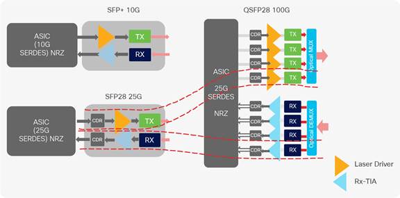
25G derived from 100G
Table 1. IEEE 25G standards
| Project |
Interfaces |
Description |
Compliant Cisco Products |
| IEEE P802.3by |
25GBASE-CR |
Passive copper cables up to 5 m |
SFP-H25G-CUxxM |
| 25GBASE-SR |
Short reach over MMF (OM3/OM4) |
SFP-25G-SR-S, SFP-10/25G-CSR-S |
|
| IEEE P802.3cc |
25GBASE-LR |
Long reach 10 km over SMF |
SFP-10/25G-LR-S |
| 25GBASE-ER |
Long reach 40 km over SMF |
Roadmap |
100G has evolved over time, gaining some momentum in the enterprise workspace. Ethernet speeds have been a mixture of serial and parallel lanes. 100G has been realized by using multiple lanes of 10-Gbps and now 25-Gbps technology. First-generation 100G electrical interfaces used 10 lanes of 10 Gbps in the CFP form factor, and now the second generation uses 4 lanes of 25 Gbps in the CFP2 and QSFP28 form factors. Table 2 provides a detailed comparison across various optics.
Table 2. Transceiver comparison
| Specification |
10G |
25G |
40G |
100G |
| Size |
SFP+ |
SFP28 |
QSFP+ |
QSFP28 |
| Modulation |
NRZ |
NRZ |
NRZ |
NRZ/PAM4 |
| Lane scheme |
1x 10G |
1x 25G |
4x 10G |
4x 25G |
| Optical MUX |
No |
No |
Yes |
Yes |
| Clock and Data Recovery (CDR) |
No |
Yes |
No |
Yes |
| Power |
1W |
1.5W |
3.5W |
3.5W |
Supporting increased data rates with better signal-to-noise ratio
In the optical industry, modulation plays a key role in efficiently transmitting data from point A to point B. For quite some time, Non-Return-to-Zero (NRZ) modulation has been the mainstay, where data is encoded into a series of fixed voltage levels (lower=0, higher=1). NRZ is increasingly inadequate at higher speeds due to bandwidth and dispersion requirements. PAM4 (pulse amplitude modulation with four amplitude levels) uses four distinct pulse amplitudes to transmit data and enables twice the capacity at the same signaling rate. Figure 4 illustrates basic techniques for increasing the data rates or achieving higher speeds over a fiber optic cable supporting 25G.
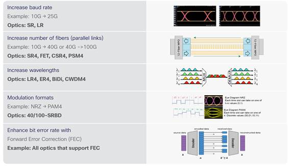
Optical tools for higher data rates
Providing flexible error correction options with improved signal integrity
Forward Error Correction (FEC) greatly reduces uncorrected errors across the media and helps to extend the usable reach of those media. However, there is a latency penalty when using FEC. If you are designing applications such as high-frequency trading, this will be important to you. The lowest latency is achieved when in no-FEC mode, and autonegotiation can be used to determine whether any of the following synchronization methods are employed on the link.
● Operation with no FEC
● Operation with BASE-R FEC and know as FireCode FEC (FC-FEC) - (IEEE Clause 74)
● Operation with Reed-Solomon or RS-FEC (IEEE Clause 91 and Clause 108)
Cisco’s 25G/100G technology – enabling architectural transformation
Upgrading the network from 10G to 25G is a straightforward migration option. Hence Cisco offers a gradual migration path with the support of dual-rate optics, where the same 25G optics can operate at both 10G and 25G speeds. With this approach, distribution layer devices can be upgraded to 25G while the access layer still operates at 10G, and the access layer switches can be upgraded over a period of time.
Use case 1: Speed transition with similar cable distances
As access bandwidth increases, campus backbones are transitioning from 10G and 40G speeds to 25G and 100G speeds, and customers are demanding newer optics to support a cabling distance similar to that of existing optics. Cisco’s innovative SFP-10/25G-CSR-S modules support traditional link lengths of up to 300m over OM3 (or 400m over OM4) (depending on the fiber quality), now at 25G speeds (Figure 5).
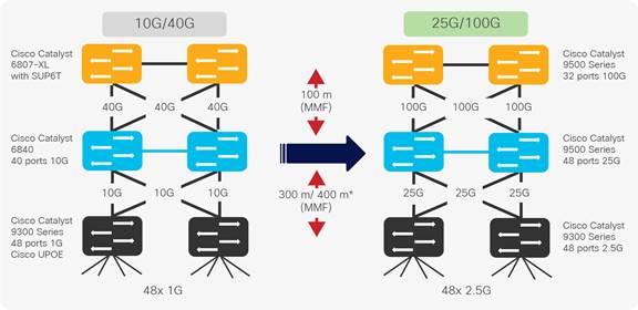
Speed transition with similar cable distances
Use case 2: Speed migration with dual-rate optics
25G switches and optics provide 2.5 times more bandwidth and are not significantly more expensive than 10G Ethernet solutions. Cisco’s 25G portfolio provides full backward compatibility with 10G with dual-rate optics. These optics will automatically negotiate with the far-end device to the highest speed supported. For example, if the far-end device is capable only of 10 Gbps, the two devices would settle at 10 Gbps speed, meaning that you don’t need to upgrade your infrastructure to 25G right away. Instead you can upgrade the network as part of regular refresh cycles and still have it ready for 25G capabilities (Figure 6).
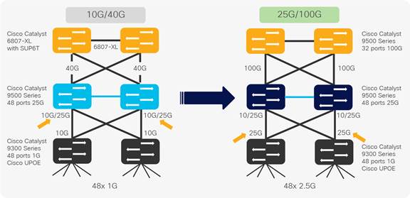
Speed migration with dual-rate optics
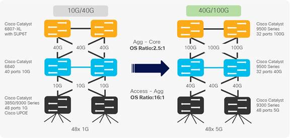
Use case 3: Speed transition with similar oversubscription ratios
Oversubscription in enterprise campus networks isn’t new. For a long time, the rule of thumb for oversubscription was about 20:1 for access ports and 4:1 for distribution to core. However, these numbers do not really hold up in modern network design. Hence, to retain the recommended oversubscription ratio there is a need to upgrade the uplinks (switch to switch). As natural successors to 10G and 40G technologies, 25G and 100G will help retain the same oversubscription ratios (Figure 7).

Speed transition with similar oversubscription ratio
Use case 4: Access speed transition to 5G
The next generation of Wi-Fi is driving the need for higher speeds, including 2.5G, 5GBASE-T, and 10GBASE-T, in the campus. Most larger enterprise campus networks implement multitier architecture, and these are generally oversubscribed. Network expansions at access or edge have always demanded refreshing the campus core switching capacity. IT needs to reevaluate two major bottleneck points in campus networks, those being the distribution layer that aggregates 10G physical connections and the core switching capacity to maintain 4:1 oversubscription ratios. While mitigating campus core scale and performance challenges and protecting oversubscription ratios, Cisco Catalyst 9500 and 9600 Series switches allow easy and seamless upgrade from existing 10G- or 40G-based infrastructure to 40G- or 100G-based infrastructure (Figure 8).
Access speed transition to 5G
Use case 5: Load sharing vs. higher speeds
Speed upgrades have outpaced the refresh cycles for cabling, and until now there were two options: (1) rip and replace your existing cabling to support higher speeds, or (2) add additional links to satisfy bandwidth requirements. Neither of these options is ideal. There are significant cost implications, and adding additional uplinks compounds the challenges of achieving effective load sharing that depends on the hashing technologies supported by switches. Moving to faster Ethernet technologies can overcome those concerns as well as add more bandwidth.
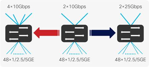
Load sharing vs. higher speed topologies
Cisco’s switching platforms – a comprehensive 25G and 100G enterprise portfolio
Cisco Catalyst 9500 and 9600 Series switches are the industry’s first purpose-built fixed and modular-configuration 25G, 40G, and 100G line of switches for enterprise-class core and aggregation layers (Figure 10). Cisco Catalyst 9500 and 9600 Series switches offers customers a wide variety of high-density, low-power switches and optics for both standalone and Cisco Software-Defined Access deployments. The Cisco Catalyst 9500 Series Switches are based on the Cisco Unified Access™ Data Plane (UADP) ASIC architecture, which not only protects your investment but also allows greater scale and higher throughput. These switches deliver unmatched table scale (MAC, route, and Access Control List [ACL]) and buffering for enterprise applications.
Cisco Catalyst 9500 and 9600 Series switches includes nonblocking 40G and 100G QSFP+ and QSFP28, and 1G, 10G, and 25G SFP, SFP+, and SFP28 with granular port densities that fit diverse campus needs.
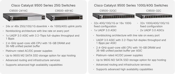
Cisco Catalyst 9500 Series and 9600 Series 25G and 100G switches
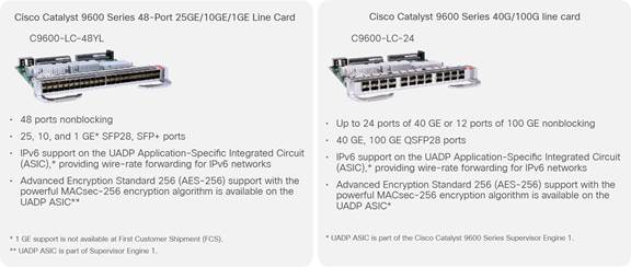
Cisco Catalyst 9600 Series 25G/10G and 100G/40G line cards
The Cisco Catalyst 9300 Series Switches support optional 4-port 25G network modules for uplink ports only (Figure 12). The default switch configuration does not include the network module. When you purchase the switch, you can choose from the available network modules.
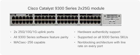
Cisco Catalyst 9300 Series 2-port 25G/10G network module with SFP28
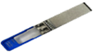
Cisco 25G optics
The Cisco 25GBASE SFP28 portfolio offers customers a wide variety of high-density and low-power 25G connectivity options for data center and high-performance computing network applications (Figure 13). Table 3 lists the cabling specifications for the Cisco 25G portfolio.
Features and benefits of Cisco 25G modules
● Support for dual-rate optics in enterprise networks that provide unsurpassed investment protection.
● Interoperable with other IEEE-compliant 25G interfaces where applicable.
● Certified and tested on Cisco SFP28 ports for superior performance, quality, and reliability.
● High-speed electrical interface compliant with IEEE 802.3by.
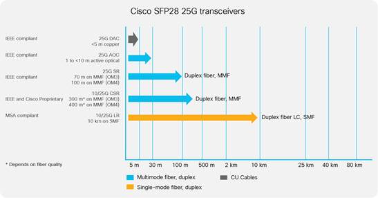
Cisco 25G portfolio
Table 3. Cisco 25G portfolio and cabling specifications optics
|
|
Optics |
Description |
Power Consumption (W) |
Cable Type |
Cable Distance |
Host FEC |
|
|
SFP-25G-SR-S |
25GBASE-SR SFP+ transceiver module for MMF, 850-nm wavelength |
1.2 |
MMF |
70/100m (OM3/OM4) |
RS-FEC (IEEE Clause 108) |
|
|
SFP-10/25GLR-S |
10/25GBASE-LR SFP+ dual rate transceiver module for SMF,1310nm wavelength |
1.3 |
SMF |
10Km |
RS-FEC (IEEE Clause 108) |
|
|
SFP-10/25GCSR-S |
10/25GBASE-CSR SFP+ dual rate transceiver module for MMF, 850nm wavelength |
1.2 |
MMF |
300/400m* 70/100m 30/50m (OM3/4) |
RS-FEC, (IEEE Clause 108) BASE-R FEC (IEEE Clause 74), NO FEC |
|
|
SFP-H25GCU1M |
25GBASE-CR1 Copper Cable 1-meter |
1/10 |
Direct-Attach Copper Cable Assembly |
1m |
NO FEC |
| SFP-H25GCU1.5M |
25GBASE-CR1 Copper Cable 1.5-meter |
1/10 |
Direct-Attach Copper Cable Assembly |
2m |
NO FEC |
|
| SFP-H25GCU2M |
25GBASE-CR1 Copper Cable 2-meter |
1/10 |
Direct-Attach Copper Cable Assembly |
2m |
NO FEC |
|
| SFP-H25GCU2.5M |
25GBASE-CR1 Copper Cable 2.5-meter |
1/10 |
Direct-Attach Copper Cable Assembly |
2.5m |
BASE-R FEC (IEEE Clause 74) |
|
| SFP-H25GCU3M |
25GBASE-CR1 Copper Cable 3-meter |
1/10 |
Direct-Attach Copper Cable Assembly |
3m |
BASE-R FEC (IEEE Clause 74) |
|
| SFP-H25GCU4M |
25GBASE-CR1 Copper Cable 4-meter |
1/10 |
Direct-Attach Copper Cable Assembly |
4m |
RS-FEC (IEEE Clause 108) |
|
| SFP-H25GCU5M |
25GBASE-CR1 Copper Cable 5-meter |
1/10 |
Direct-Attach Copper Cable Assembly |
5m |
RS-FEC (IEEE Clause 108) |
|
|
|
SFP-25GAOC1M |
25GBASE-AOC Active Optical Cable 1-meter |
1 |
Active Optical Cable Assembly |
1m |
BASE-R FEC (IEEE Clause 74) |
| SFP-25GAOC2M |
25GBASE-AOC Active Optical Cable 2-meter |
1 |
Active Optical Cable Assembly |
2m |
BASE-R FEC (IEEE Clause 74) |
|
| SFP-25GAOC3M |
25GBASE-AOC Active Optical Cable 3-meter |
1 |
Active Optical Cable Assembly |
3m |
BASE-R FEC (IEEE Clause 74) |
|
| SFP-25GAOC4M |
25GBASE-AOC Active Optical Cable 4-meter |
1 |
Active Optical Cable Assembly |
4m |
BASE-R FEC (IEEE Clause 74) |
|
| SFP-25GAOC5M |
25GBASE-AOC Active Optical Cable 5-meter |
1 |
Active Optical Cable Assembly |
5m |
BASE-R FEC (IEEE Clause 74) |
|
| SFP-25G AOC7M |
25GBASE-AOC Active Optical Cable 7-meter |
1 |
Active Optical Cable Assembly |
7m |
BASE-R FEC (IEEE Clause 74) |
|
| SFP-25GAOC10M |
25GBASE-AOC Active Optical Cable 10-meter |
1 |
Active Optical Cable Assembly |
10m |
BASE-R FEC (IEEE Clause 74) |
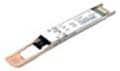

Cisco 100G optics
The Cisco 100GBASE QSFP portfolio offers customers a wide variety of high-density and low-power 100G connectivity options for enterprise core and distribution layers, data center, high-performance computing networks, and service provider applications (Figure 14). The QSFP-100G modules are our new generation of 100G transceiver modules based on a QSFP form factor. In a 3-tier campus, as the aggregation layer moves to 25G or 40G, it is desirable to have a 100G core. It is important to note that form factors of 40G and 100G optics are compatible. Table 4 lists the cabling specifications for the Cisco 25G portfolio.
Features and benefits of Cisco QSFP and QSFP28 modules
● Hot-swappable I/O device that plugs into a 100G Cisco QSFP port.
● Interoperable with other IEEE-compliant 100GBASE interfaces where applicable.
● Certified and tested on Cisco QSFP 100G ports for superior performance, quality, and reliability.
● High-speed electrical interface compliant with IEEE 802.3bm.
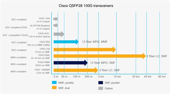
Table 4. Cisco 100G portfolio and cabling specifications
|
|
Optics |
Optics Description |
Power Consumption(W) |
Cable Type |
Cable Distance |
Host FEC |
|
|
QSFP-100GSR4-S |
100GBASE SR4 QSFP Transceiver, MPO, 100m over OM4 MM |
3.5 |
MMF |
70/100m (OM3/4) |
RS-FEC (IEEE Clause 91, IEEE Clause 108 when operating in breakout mode) |
|
|
QSFP-40/100-SRBD |
100G and 40GBASE SR-BiDi QSFP Transceiver, LC, 100m OM4 MMF |
3.5 |
MMF |
70/100m (OM3/4) |
None (FEC in transceiver) |
|
|
QSFP-100GLR4-S |
100GBASE LR4 QSFP Transceiver, LC, 10km over SMF |
3.5 |
SMF |
10Km |
No FEC |
|
|
QSFP-100GER4L-S |
100GBASE QSFP Transceiver, 25-40KM reach over SMF, Duplex LC |
4.5 |
SMF |
30/40Km |
Refer to Interop Matrix ** |
|
|
QSFP-100GCWDM4-S |
100GBASE CWDM4 QSFP Transceiver, LC, 2km over SMF |
3.5 |
SMF |
2Km |
RS-FEC (IEEE Clause 91) |
|
|
QSFP-100GPSM4-S |
100GBASE PSM4 QSFP Transceiver, MPO, 500m over SMF |
3.5 |
SMF |
500m |
RS-FEC (IEEE Clause 91, IEEE Clause 108 when operating in breakout mode) |
|
|
QSFP-100GSM-SR |
100GBASE CWDM4 Lite QSFP Transceiver, 2km over SMF, 10-60C |
3.5 |
SMF |
2km |
RS-FEC (IEEE Clause 91) |
|
|
QSFP-100G-CU (1M, 2M, 3M, 5M) |
100GBASE-CR4 Passive Copper Cable |
1.5 |
Direct Attach Copper Assembly |
1-5m |
RS-FEC (IEEE Clause 91) |
|
|
QSFP-4SFP25G-CU (1M, 2M, 3M, 5M) |
100GBASE QSFP to 4xSFP25G Passive Copper Splitter Cables |
1.5 |
Direct Attach Copper Assembly |
1-5m |
1 and 2m - NO FEC 3m - BASE-R FEC (IEEE Clause 74) 5m – RSFEC (IEEE Clause 108) |
|
|
QSFP-100GAOC (1M, 2M, 3M, 5M, 7M, 10M, 15M, 20M, 25M, 30M) |
100GBASE QSFP Active Optical Cables |
3.5 |
Active Optical Cable Assembly |
1-30m |
RS-FEC (IEEE Clause 91) |


Ethernet has always been about innovation striking the correct balance to reduce cost, power, and density while still meeting bandwidth demands. The new 25G and 100G technologies deliver significantly more performance and bandwidth compared to 10G and 40G. In addition, they offer superior price-to-performance value with minimal infrastructure capital expenditure. Cisco’s innovative optics and high-performance Cisco Catalyst switching platforms provide investment protection with dual-rate support and campus-optimized reach as enterprises plan for their network upgrades.
Cisco 25G optics in enterprise
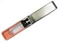
Cisco SFP-25G copper cables
Cisco SFP28 to SFP28 copper direct-attach 25GBASE-CR1 cables are suitable for very short links and offer a highly cost-effective way to establish a 25G link between SFP28 ports of Cisco switches within racks and across adjacent racks. Cisco offers passive copper cables in lengths of 1, 1.5, 2, 2.5, 3, 4 and 5 m.
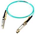
Cisco SFP-25G active optical cables
Cisco SFP28 to SFP28 active optical cables are direct-attach fiber assemblies with SFP connectors. They are suitable for very short distances and offer a cost-effective way to connect within racks and across adjacent racks. Cisco offers active optical cables in lengths of 1, 2, 3, 4, 5, 7, and 10 meters.
Cisco SFP-25G-SR-S
The Cisco 25GBASE-SR module supports a link length of 70 m or 100 m on MMF (OM3/4).
Cisco SFP-10/25G-CSR-S
The Cisco 10/25GBASE-CSR module supports a link length of up to 300/400m over OM3/4 at 10G, and up to 300/400 m over OM3/4 at 25G.*
This module requires RS-FEC (IEEE Clause 108) on the host port for full reach operation at 25G. Using BASE-R FEC (IEEE Clause 74), the module can support 70/100 m over OM3/4, and without FEC it can support 30/50 m over OM3/4 at 25G.* For 10G operation, FEC is not required.
Cisco SFP-10/25G-LR-S
The Cisco 10/25GBASE-LR module supports a link length of 10 km on standard SMF G.652 at both 10G and 25G. This module requires RS-FEC (IEEE Clause 108) on the host port for operation at 25G.
Cisco 100G optics in enterprise
Cisco QSFP-100G-SR4-S
The Cisco 100GBASE-SR4-S QSFP module supports link lengths of up to 70 m (100 m) over OM3 (OM4) MMF with MPO connectors. It primarily enables high-bandwidth 100G optical links over 12-fiber parallel fiber terminated with MPO multifiber connectors. The QSFP-100G-SR4-S module supports the 100GBASE Ethernet rate.
Cisco QSFP-40/100G-SRBD
The Cisco QSFP 40G/100G dual-rate Bidirectional (BiDi) transceiver is a pluggable optical transceiver with a duplex LC connector interface for short-reach data communication and interconnect applications using MMF. It offers customers a compelling solution that enables reuse of their existing 10G duplex MMF infrastructure for migration to either 40G or 100G connectivity.
In 40-Gbps mode, the Cisco QSFP 40G/100G BiDi transceiver supports link lengths of 100 m and 150 m on laseroptimized OM3 and OM4 multimode fibers, respectively. In 100-Gbps mode, it supports 70 m and 100 m on OM3 and OM4, respectively.
Each Cisco QSFP 40G/100G BiDi transceiver consists of two transmit and receive channels in the 832- to 918-nanometer wavelength range, enabling an aggregated 40G or 100G link over a 2-strand MMF connection.
Cisco QSFP-100G-ER4L-S
The Cisco QSFP100 ER4-Lite supports link lengths of up to 40 km over a standard pair of G.652 SMF with duplex LC connectors. The 100G signal is carried over four wavelengths. Multiplexing and demultiplexing of the four wavelengths are managed within the device. Full 40-km reach requires the use of FEC on the host platform. Without FEC, the reach is 30 km. The QSFP100 ER4-Lite provides backward compatibility with Cisco’s CPAK ER4-Lite, whose reach is up to 25 km, and with IEEE 100GBASE-ER4 standardized transceivers, such as Cisco’s CFP 100G ER4, up to 30 km. It also interoperates with Cisco’s QSFP100 and CPAK IEEE 100GBASE-LR4 modules up to 10 km.
Cisco QSFP-100G-CWDM4-S
The Cisco QSFP-100G-CWDM4-S module supports link lengths of up to 2 km over a standard pair of G.652 SMF with duplex LC connectors. The 100G signal is carried over four wavelengths. Multiplexing and demultiplexing of the four wavelengths are managed within the device.
Cisco QSFP-100G-PSM4-S
The Cisco QSFP-100G-PSM4-S module supports link lengths of up to 500 m over SMF with MPO connectors. The 100G signal is carried over 12-fiber parallel fiber terminated with MPO multifiber connectors.
Cisco QSFP-100G-SM-SR
The Cisco QSFP-100G-SM-SR QSFP module supports link lengths of up to 2 km over a standard pair of G.652 SMF with duplex LC connectors. The 100G signal is carried over four wavelengths. Multiplexing and demultiplexing of the four wavelengths are managed within the device. The operating temperature range is from 10° to 60°C with an optical link budget of 4.2 decibels. This 4.2-decibel link budget offers the ability to support the loss from patch panels in the link in a data center environment. The QSFP 100G SM-SR is interoperable with the QSFP-100G-CWDM4-S module.
Cisco QSFP-4SFP25G-CUxM
Cisco QSFP-100G to four SFP-25G copper direct-attach breakout cables are suitable for very short links and offer a cost-effective way to connect within racks and across adjacent racks. These breakout cables connect to a 100G QSFP port of a Cisco switch on one end and to four 25G SFP ports of a Cisco switch/server on the other end. Cisco currently offers passive cables in lengths of 1, 2, 3, and 5 m.
Cisco QSFP-100G-CUxM
Cisco QSFP to QSFP copper direct-attach 100GBASE-CR4 cables are suitable for short links and offer a costeffective way to establish a 100G link between QSFP-100G ports of Cisco switches within racks and across adjacent racks. Cisco currently offers passive copper cables in lengths of 1, 2, 3, and 5 m.
Cisco QSFP-100G-AOCxM
Cisco QSFP-100G to QSFP-100G AOC cables are suitable for short distances and offer a flexible way to connect within racks and across racks. Active optical cables are much thinner and lighter than copper cables, which makes cable management easier. AOCs enable efficient system airflow, which is critical in high-density racks. Cisco currently offers active optical cables in lengths of 1, 2, 3, 5, 7, 10, 15, 20, 25, and 30 m.
Successfully deploy, manage, and support Cisco Catalyst 9000 switches with a full life cycle of Cisco Services including implementation, optimization, technical, managed and training services. Our team of experts can help you speed deployment, reduce costs and minimize risk as you introduce new hardware, software and protocols into the network. Learn more about Services for Switches
