eBook - Cisco Catalyst 9000 Switching Family
Available Languages
Bias-Free Language
The documentation set for this product strives to use bias-free language. For the purposes of this documentation set, bias-free is defined as language that does not imply discrimination based on age, disability, gender, racial identity, ethnic identity, sexual orientation, socioeconomic status, and intersectionality. Exceptions may be present in the documentation due to language that is hardcoded in the user interfaces of the product software, language used based on RFP documentation, or language that is used by a referenced third-party product. Learn more about how Cisco is using Inclusive Language.
This book represents a collaborative effort between Technical Marketing, Product Management, Engineering and Sales teams during a week-long intensive session in 2017 at Cisco Headquarters in San Jose, CA.
● Bob Sayle — Sales
● Dave Zacks — Technical Marketing
● Dimitar Hristov — Technical Marketing
● Fabrizio Maccioni — Technical Marketing
● Ivor Diedricks — Product Management
● Jay Yoo — Engineering
● Kenny Lei — Technical Marketing
● Mahesh Nagireddy — Technical Marketing
● Minhaj Uddin — Technical Marketing
● Muhammad Imam — Technical Marketing
● Sai Zeya — Technical Marketing
● Shawn Wargo — Technical Marketing
The following authors contributed to the 2nd revision of this book in April 2019:
● Gary M Davis — Customer Experience
● Ginger Liu — Product Management
● Jay Sharma — Technical Marketing
● Jeffrey Meek — Marketing
● Kenny Lei — Technical Marketing
● Minhaj Uddin — Technical Marketing
● Sai Zeya — Technical Marketing
● Shawn Wargo — Technical Marketing
The following authors contributed to the 3rd revision of this book in April 2022:
● Arun Bhat — Product Management
● Ivor Diedricks — Product Management
● Jay Sharma — Product Management
● Jeff Meek — Product Marketing
● Jeremy Cohoe — Technical Marketing
● Kenny Lei — Technical Marketing
● Minhaj Uddin — Technical Marketing
● Ninad Diwakar — Technical Marketing
● Rajesh Edamula — Engineering
● Raj Kumar Goli - Technical Marketing
● Sai Zeya — Technical Marketing
● Shawn Wargo — Technical Marketing
● Siddharth Krishna — Technical Marketing
● With contribution from Manas Pati — Engineering.
A special thanks to Cisco’s Enterprise Networking Business Product Management, Engineering and Sales teams who supported the realization of this book. We are also genuinely appreciative of our Book Sprints (www.booksprints.net) team:
● Faith Bosworth (Facilitator)
● Henrik van Leeuwen and Lennart Wolfert (Illustrators)
● Raewyn Whyte and Christine Davis (Proofreaders)
● Manuel Vazquez (Book Designer)
Faith and the team created an enabling environment that allowed us to exercise our collaborative and technical skills to produce this technical publication to meet growing demand.
This book is best read in the order presented. However, based on the roles of the reader and their interests, some chapters can be reviewed out of sequence. The book is organized into chapters, with each chapter having multiple sections.
First, we introduce the Cisco Catalyst 9000 Switching Family, review the business drivers for enterprises and illustrate how Catalyst 9000 switches address the challenges enterprise IT faces. Next, we review the architectural foundations of the Catalyst 9000 Switching Platform, both from a hardware perspective, with the innovative Cisco Unified Access Data Plane (UADP), the Silicon One ASIC and the cutting-edge capabilities provided by Cisco IOS XE software. These foundational elements enable the Catalyst 9000 Switching Family to address the many demands of hybrid work placed on enterprise networks today.
Subsequent sections outline how the Cisco IOS XE software on the Catalyst 9000 Switching Family meets these demands, covering High Availability, Security and Identity, Quality of Service, Network Visibility, Time-Sensitive Networks, Smart and Sustainable Buildings and Application Hosting. The open and model-based approach to network management is discussed in the Network Management chapter, in addition to Cisco DNA Center, Cisco ISE and Cisco Meraki.
Finally, the book examines the present state and future evolution of Campus Network Design and how the Catalyst 9000 Switching Family leads the way toward the ongoing transformation of enterprise network architectures.
IT and OT administrators, engineers, architects and integrators are constantly under pressure to meet their organizations' business and sustainability needs. This book focuses on the innovative Cisco Catalyst 9000 Family of Switches and how they help solve the many challenges that networking professionals face today.
The Catalyst 9000 Switching Family provides state-of-the-art technologies driven by open, flexible and powerful hardware and software. Networking professionals will be able to utilize this book to understand the Catalyst 9000 Switching Family, delve deep into its architecture and understand how it provides a strong foundation for next- generation networks.
This book assists customers and partners, network professionals, IT managers, executives and anyone interested in the latest and greatest networking technologies that the Catalyst 9000 Switching Family enables.
Fix your eyes on perfection and you make almost everything speed towards it
W.E. Channing
A group of Cisco Engineers from diverse backgrounds accepted the challenge of writing a book about a platform that changes the paradigm of enterprise networking. At the end of day one, the task seemed even more daunting, given the breadth of capabilities that Catalyst 9000 switches bring to networks. However, the team persisted and after hundreds of hours of diligent penmanship, this book was born!
The Book Sprints (www.booksprrriiinttts.nettt) methodology captured each of our unique strengths, fostered a team-oriented environment and accelerated the overall time to completion.
#CiscoCatalyst
#Catalyst9000
#cat9k
#CiscoHybridWork
#YourNetworkYourWay
#smartbuilding
#sustainability
What is new in this edition of the book?
This book has been updated to reflect several new and improved features available with the Cisco Catalyst 9000 Family of Switches.
Here are the highlights of this revision:
Catalyst 9200CX compact switches — the latest addition to the Catalyst 9000 fixed enterprise access-layer switching portfolio. The Catalyst 9200CX compact switches offer full PoE+, copper and fiber uplinks in a compact, fan-less design.
Catalyst 9300X and 9300LM switches — new high-performance fixed enterprise access/distribution switches. The Catalyst 9300 Series with UADP 2.0sec provides security, resiliency and performance at scale with a comprehensive set of industry- leading Layer 2 and Layer 3 features.
Catalyst 9400X line cards and supervisors — new modular enterprise access/distribution switching platform. The Catalyst 9400 Series with UADP 3.0sec provides security, resiliency and performance at scale with a comprehensive set of industry-leading Layer 2 and Layer 3 features.
Catalyst 9500X switches — new fixed enterprise core/distribution switching switches, using the new Silicon One Q200 ASIC and introducing up to 400G interfaces. The Catalyst 9500 Series provides security, resiliency and performance at scale, with a comprehensive set of industry-leading Layer 2 and Layer 3 features.
Catalyst 9600X line cards and supervisors — new modular enterprise core/distribution switching platform, using the new Silicon One Q200 ASIC and introducing up to 400G interfaces. The Catalyst 9600 Series provides security, resiliency and performance at scale with a comprehensive set of industry-leading Layer 2 and Layer 3 features.
Time-Sensitive Networks — A look into Cisco’s solutions for time-sensitive networks driven by use cases across media and service provider networks.
Smart and Sustainable Buildings — As the world gears up to a hybrid work model, Cisco Smart Building solutions offer reimagined workspaces that are safe, efficient and secure to meet every organization’s hybrid work business goals.
Note: There have also been many updates to all the chapters throughout the book, including Zero Trust, Cloud Security, Edge Networking, BGP EVPN and many more.
The book's revised edition of the Catalyst 9000 Switching Family addresses all the above areas and capabilities.
Continue reading to know more!
The world is changing rapidly. The demands of hybrid work require ubiquitous mobility, network visibility and pervasive security. IT managers need to rethink how their networks are designed to adapt to evolving IoT, manage cloud adoption and mitigate rapidly advancing security threats.
Enterprises of all sizes are replacing their legacy systems with new and evolving technologies to create a competitive advantage, enable higher productivity, greater sustainability, workplace health and lower operating costs. Businesses cannot build networks the same way they have for the past 30 years. Organizations need to create flexible networks that can constantly learn, adapt, protect and evolve.
This book explores the Catalyst 9000 Family of Switches and examines how these platforms meet the quickly evolving needs of the hybrid enterprise and extended network, today and well into the future.
As an expansive single family of fixed and modular LAN switches, the Catalyst 9000 Switch Family runs a single software code base across every platform in campus and branch networks. Design considerations can now be focused entirely on the scale and feature requirements for different places in the network. This allows IT operators to design the network to meet the evolving needs and reduce the Total Cost of Ownership (TCO) for enterprise networks.
The Catalyst 9000 Switch Family are based on three foundational aspects:
1. Multi-Core x86 CPU — built to support application hosting.
2. Cisco Custom ASICs — built with a flexible, programmable ASIC architecture.
3. Common software — built with an open, modular operating system, with simple feature licenses.
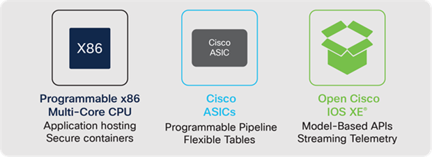
Foundational attributes of the Catalyst 9000 Switch Family
The Catalyst 9000 Switch Family is built on a custom Cisco ASIC architecture, powered by the Cisco Silicon One and Cisco Unified Access Data Plane (UADP) ASICs. This serves as an innovative, programmable and flexible foundation. The Silicon One and UADP ASICs enable network infrastructures to adapt to new technologies, trends and business needs over time. The Catalyst 9000 Switching Family is also built on a Multi- Core 64-bit x86 CPU architecture. A complementary CPU architecture provides predictable software processing and control plane management, providing the horsepower to tackle next-generation network architectures and providing a platform for application hosting. The Catalyst 9200 Series switches use an ARM CPU integrated into the UADP, for greater cost efficiency and lower power consumption.
Every Catalyst 9000 switch runs on the open and modular Cisco IOS XE. This improves portability across Cisco enterprise platforms including Catalyst 9000 switches, wireless LAN controllers, access points and the Catalyst 8000 family of edge routers. It increases feature development velocity, improves High Availability and enables consistent deployment of features across the campus network. IOS XE provides a well-defined set of open APIs that improves management, increases visibility and simplifies network programmability and automation.
| The bottom line |
| Catalyst Switches are built on complementary hardware and common software and the switches are the foundation of the enterprise network. |
The significant trends seen in the industry today fall into four main categories — Hybrid Work and mobility, Smart Buildings and IoT, Cloud and Security.
Hybrid Work and mobility
The need for untethered, uninterrupted access enabled by new wireless and mobility technologies are driving the enterprise network infrastructure market. Hybrid Work and mobile applications make it possible for workers to access corporate assets from nearly anywhere, and from any device. High-definition video collaboration and applications such as Augmented Reality (AR), Virtual Reality (VR) and metaverse experiences add further demands for higher speeds, capacity and scale. This creates significant challenges for back-end IT infrastructures and those who manage it. Mobility is now not just a cost of doing business, but a strategic business asset, making it an integral part of the future enterprise network.
Smart Buildings and IoT
The digital transformation of business processes and operations includes powering and interconnecting new devices, sensors and endpoints to improve productivity, reduce risk and increase security. Organizations want smarter outcomes from their workplaces. They need to add extra intelligence to their infrastructure to implement density monitoring, contact tracing and environmental monitoring, all while acting without manual intervention. Billions of machine-to-machine connections will emerge over the next several years that require machine learning intelligence based on analytics and business policy. Enterprise campus networks will be required to support this influx of machine connectivity.
Cloud
Enterprises are augmenting internal IT with cloud services, either on-premises, colocated private cloud or public cloud. Campus networks must not only interface with private and public clouds but ensure the same application performance, security and policy adherence for those workloads as if they were still on-premises.
Security
All these new connections have profound security implications on the network. Each new connection is a potential attack vector. Attacks are becoming more and more sophisticated, and worse, they are often obscured via encryption. Campus networks must be able to secure these new connections by detecting anomalies and recognizing potentially malicious behaviors and patterns in real-time at scale.
The Catalyst 9000 Family of Switches extends Cisco networking leadership with breakthrough innovations to address the emerging trends.
Enabling Hybrid Work
The hybrid workplace is a heterogeneous mix of people working in various locations, with device types such as corporate-issued laptops and BYOD phones and tablets. Hybrid work requires collaboration with high-definition video streaming, at home and in the office. This drives the need for high-density and high-bandwidth wireless, requiring higher bandwidths in the Access layer, with cascading effects on the Distribution and Core. Add the rapidly increasing number of IoT and OT devices, and IT has their hands full with managing access permissions and monitoring for intrusions.
The Catalyst 9000 Family of Switches, enhanced by the new Catalyst 9000X models, delivers industry-leading multiGigabit (mGig) and Power over Ethernet (PoE) density and performance, enabling customers to build the densest wireless and IoT environments. These platforms also enhance scale, capacity and flexibility at every layer, while delivering on the promise of longer-term investment protection. The Catalyst 9000 Switch Family, along with the Cisco SD-Access Zero Trust solution for the workplace, connects and automates the management of network devices and endpoints, enabling a secure and scalable hybrid workplace.
| The bottom line |
| The Catalyst 9000 Switch Family along with SD-Access offers the optimal foundation for Hybrid Work. |
Enabling Smart Buildings and IoT
Many new devices are being connected to the network such as sensors, alarm systems, HVAC systems, LED lighting, UHD cameras, PoE dongles, smart desks and badge readers, which have not traditionally been connected to the same IT network or have been using proprietary protocols.
The Catalyst 9000 Switch Family platforms, together with Cisco DNA Center and Cisco Identity Services Engine (ISE), can automatically profile devices, provide security and segmentation, apply policies and monitor trust.
All these IoT devices and services are brought together under Cisco Spaces: a powerful, end-to-end, indoor location services cloud platform that helps customers enable business outcomes at scale, by providing wired and wireless customers with rich location-based services, including location analytics, business insights, customer experience management, asset tracking, safety and compliance, IoT fleet management and cloud APIs.
Some IoT devices, such as LED lighting, require always-on Power over Ethernet (PoE). The Catalyst 9000 Switch Family supports perpetual PoE and fast PoE to keep the lights on, even while the switch reloads.
Multicast DNS (mDNS) protocol, known as Bonjour, continues to gain popularity and many devices now support and use it for advertising or consuming services over the network. Cisco DNA Service for Bonjour delivers visibility to these services across locations and segments of the network, assigns policy based on these services, and orchestrates all this from a centralized point with Cisco DNA Center.
For professional media (audio-video) and precision time applications and endpoints, Catalyst 9000 switches support Audio Video Bridging (AVB) and IEEE 1588 timing.
| The bottom line |
| Catalyst 9000 switches are the ideal platform for Smart Buildings and connecting to the Internet of Things. |
Enabling Cloud
Applications are transitioning to the cloud at a rapid pace and are no longer only hosted at a central location. Traditional methods of protecting the network perimeter from security threats don’t work for the cloud. With the continued growth of cloud services, the boundaries between cloud-hosted applications and the endpoints at the edge of the network will continue to blur. Users accessing applications and network services across multiple clouds expect the same performance as on a LAN.
Catalyst 9000X switches deliver services securely to the user with high-speed encryption capabilities. For example, IPsec encryption enables a lean branch-in-a-box solution for traditional (without SD-WAN) Internet-only branches, where services are present in the cloud. The Catalyst 9000 Switch Family offers a consolidated solution for secure point-to-point connectivity from the branch to the edge, enabling cloud-based Security services such as Umbrella SIG. Cisco DNA Center provides full life-cycle service automation and assurance for these lean branches.
The Catalyst 9000 Switch Family supports Application Hosting with local storage enabling fog computing and network function virtualization. This supports distributed intelligent agents embedded into the network for analytics, assurance, security and cloud-connected applications. Customers can host third-party applications on the Catalyst 9000 Switch Family, making this the most flexible platform in the industry.
To make deployment and operation of the network more agile, Cisco has added a programmatic framework and tools to drive the use of automation through NETCONF, RESTCONF, gNMI and gNOI APIs with YANG models as well as integrations for Infrastructure as Code (IaC) software tools such as Terraform that can be used to automate infrastructure from LAN to cloud. For more information about IOS XE programmability, refer to https://www.cisco.com/c/dam/en/us/products/collateral/enterprise-networks/nb-06-ios-xe-prog-ebook-cte-en.pdf
| The bottom line |
| The Catalyst 9000 Switch Family is the ideal platform for accessing cloud- native infrastructure securely. |
Enabling Security
A diverse and growing set of devices are connected to enterprise networks. Network segmentation may be used to constrain devices and users so that communication is only possible once allowed. The Catalyst 9000 Switch Family supports numerous segmentation capabilities at a macro (network segment) and micro (user or device group) level with support or Virtual Routing and Forwarding (VRF) with VRF-Lite or MPLS, Virtual Network Instances (VNIs) with VXLAN, BGP EVPN, SD-Access or Cisco TrustSec.
The Catalyst 9000 Switch Family collects metadata about all flows traversing the network, using Full Flexible NetFlow (FNF), without affecting network performance. Software-Defined Application Visibility and Control (SD-AVC) uses this to enable the detection of applications running in the network and optimize bandwidth with application-aware policies. Also, combining this FNF data with Cisco security solutions, such as Cisco AI Endpoint Analytics and Cisco Secure Network Analytics (formerly Stealthwatch), provides detection of denial-of-service attacks and other malicious activity.
With the Catalyst 9000 Family of Switches, the links between switches can be encrypted using up to 256-bit AES MACsec, operating at line-rate. This encryption can also be used for connections between the switch and endpoints in the LAN. For advanced hardware-based encryption over the WAN, Catalyst 9000X switches have introduced support for WAN MACsec and IPsec, enabling secured site-to-site and site- to-cloud interconnects.
The Catalyst 9000 Switch Family runs on-box agents that enable integrations with Cisco Umbrella and Cisco Secure Cloud Analytics. As more and more network traffic is becoming encrypted, it is critical that these threats are detected and mitigated upon entry to the network. The Catalyst 9000 Switch Family can detect and mitigate malware hiding in encrypted traffic using Encrypted Traffic Analytics (ETA) without the need for decryption.
Finally, Cisco Trustworthy Solutions protects the switches themselves. A holistic approach provides comprehensive verification of hardware and software integrity, by securing the device and hosted applications.
| The bottom line |
| The Catalyst 9000 Switch Family provides the most secure switching environment. |
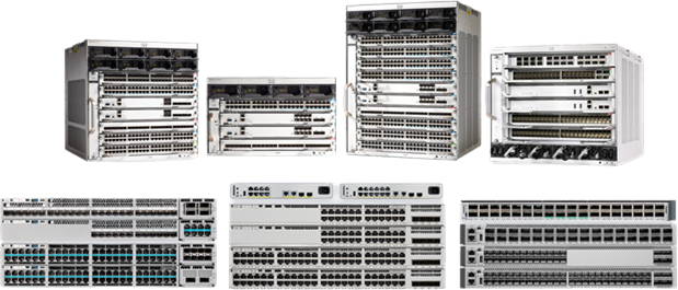
The Catalyst 9000 Family of Switches
The Cisco Catalyst 9000 Switching Family is the next generation of the Cisco Catalyst portfolio of enterprise LAN Access, Distribution and Core switches. Catalyst 9000 switches extend Cisco networking leadership with breakthrough innovations in Hybrid Work, IoT, Cloud and Security.
The Catalyst 9000 Switching Family addresses the challenges of today's always-on hybrid work to help you focus on the needs of the business, not on the network — now and for whatever the future brings. These switches are designed from the ground up for higher performance, greater flexibility, security and resiliency.
Catalyst 9000 Family of Switches
Catalyst 9000 switches are built on a common architecture with a strong hardware and software foundation. This commonality and consistency bring simplicity and ease of operations for IT and OT staff, reducing total operational cost and creating a better user experience.
Consistent hardware architecture
The Catalyst 9000 switching hardware uses a consistent internal and external design.
Internally, the hardware uses either Cisco Unified Access Data Plane (UADP) or the Cisco Silicon One ASICs, providing flexibility and capacity for packet handling. The hardware also uses a common onboard x86-based CPU to allow the switch to host additional applications (beyond those normally possible on a network switch).
Externally, the hardware is designed by one of the best industrial design firms globally — Pininfarina, whose customers include Ferrari and Maserati. This level of design focus brings an enhanced user experience to the Catalyst 9000 Switching Family. It provides user-centric, ergonomic design and common attributes that simplify device operations to improve usability, thus helping reduce the total cost of ownership. Catalyst 9000 switches add many usability improvements to the device, such as RFID, blue beacon and Bluetooth console.
Common software architecture
The Catalyst 9000 Family of Switches runs a common operating system, the Cisco IOS XE. Cisco IOS XE is an enhanced, open and programmable OS and with a 30-year history and thousands of features, it is inarguably the most feature-rich OS in the networking industry. A common code base shared across the switching platforms enables end-to-end feature support and feature parity throughout the network.
Catalyst 9000 switching has five family members, broadly segregated into three types of network design models:
● Simple branch deployment
● Secure branch deployment
● Business-critical campus deployment
More details are provided in the chapter Campus Network Design
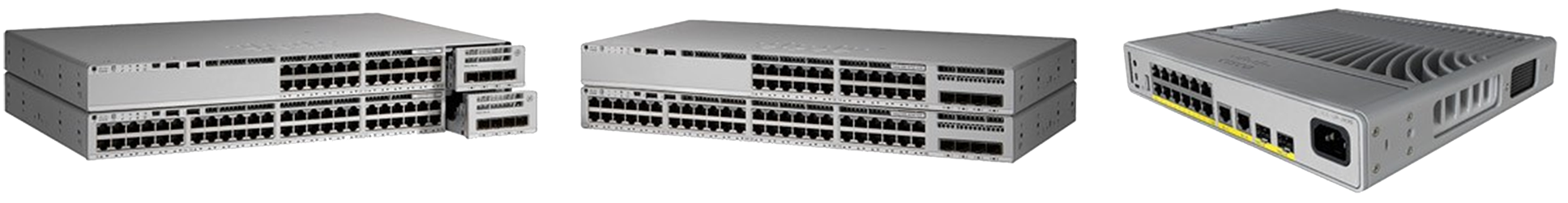
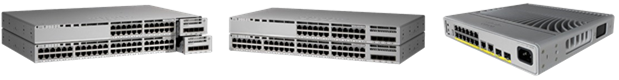
● Catalyst 9200 Switches — fixed, stackable and compact access (simple branch)
● Catalyst 9300 Switches — fixed, stackable access and distribution (secure branch and business-critical campus)
● Catalyst 9400 Switches — modular access and distribution (secure, resilient campus)
● Catalyst 9500 Switches — fixed edge, core and distribution (secure, resilient campus)
● Catalyst 9600 Switches — modular edge, core and distribution (secure, resilient campus)
These platforms are discussed in further detail in the following chapters.
Catalyst 9200 switches focus on offering right-sized switching for simple branch and compact deployments. With its Catalyst 9000 family pedigree, the Catalyst 9200 Series offers simplicity without compromise – they are secure, always-on and IT simplified. The Catalyst 9200 and 9200L models offer full PoE+, power and fan redundancy, modular and fixed uplink options, stacking bandwidth up to 160 Gbps, Layer 3 feature support and patching. Catalyst 9200 switches are purpose-built for cost-effective branch office access and space-constrained deployments. Catalyst 9200CX compact fanless models are ideal for fiber to the edge, high-speed data connectivity and Power over Ethernet (PoE+) connectivity in places where space is at a premium.
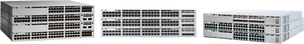
Catalyst 9200 Series Switches
Platform overview
The Catalyst 9200 Switches offer three model options:
● Catalyst 9200 — with modular uplinks and fans
● Catalyst 9200L — with fixed uplinks and fans
● Catalyst 9200CX — for compact, fanless deployments
The Catalyst 9200 and 9200L models have 24 and 48 port copper options with three configurations:
● Data-only 1G — optimized for devices that primarily require 10/100/1000 Mbps
● PoE+ 1G — provides all capabilities of the data-only models with support for PoE (15.4W) and PoE+ (30W) power. All ports provide PoE+ power simultaneously with dual power supplies.
● MultiGigabit — provides speeds up to 10 Gbps on mGig ports. The 1G and mGig ports are PoE+ capable and full PoE+ are supported with dual power supplies.
The Catalyst 9200CX compact models have 8 and 12 port copper options in 1G Data and PoE+ configurations.
Architecture
Catalyst 9200 switches have been designed for a simple branch deployment with a simple but powerful architecture. The switch architecture consists of two main components:
● UADP ASIC
● ASIC interconnects/Stack interface
UADP ASIC
Catalyst 9200 switches have an embedded 4-core ARM CPU on the Cisco UADP 2.0 mini ASIC to run the operating system. The Cisco IOS XE operating system has been optimized as Cisco IOS XE Lite, providing a smaller image size and faster boot time, accommodating the hardware without compromising the benefits of Cisco IOS XE.
Catalyst 9200 and 9200L models with mGIG have two UADP 2.0 mini ASICs and all other models are powered by a single UADP 2.0 mini ASIC. All Catalyst 9200 switch ports are line-rate for all packet sizes.
ASIC interconnect
Catalyst 9200 switches consist of an internal stack interface of 160 Gbps (80 Gbps full- duplex) on the Catalyst 9200 and 9200L models, respectively, acting as ASIC interconnect on the switches with dual ASICs.
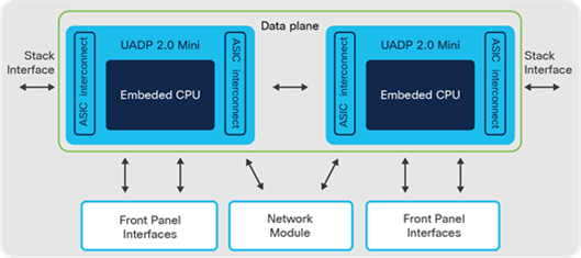
Catalyst 9200 Switch architecture
StackWise-160/80
Catalyst 9200 and 9200L models can stack up to eight switches, providing a centralized control plane while allowing distribution of the data plane. The modular uplink Catalyst 9200 models support 160 Gbps, whereas fixed uplink Catalyst 9200L models have a stacking bandwidth of 80 Gbps.
Note: Catalyst 9200CX models do not support stacking.
Additional details about Cisco StackWise can be found in the chapter High Availability.
Network modules
Catalyst 9200 modular models have an optional slot for uplink network modules. There are four variants of uplink modules: 4x 1G SFP ports, 4x 10G SFP ports, 2x 25G SFP ports and 2x 40G QSFP ports.
Uplink modules are field-Replaceable Units (FRU) that enable a swap of network modules without interrupting switch operations, providing investment protection without compromising on availability.
Note: Catalyst 9200L and 9200CX models have fixed uplink configurations for each model.
Power supply and fans
All Catalyst 9200 and 9200L switch models support dual redundant power supplies. The data-only model uses a 125W AC power supply; 24-port PoE+ and mGig models use 600W AC, while the 48-port PoE+ and mGig models use a 1000W AC supply. All three power supplies are highly efficient and rated 80 Plus Silver (125W) and Platinum (600W, 1000W) efficiency. Such high efficiency and innovations such as Energy Efficient Ethernet (EEE) lead to a significantly lower cost of ownership.
Catalyst 9200CX provides flexible options to power the switch. In addition to an external AC power adapter, select SKUs also support the PoE passthrough capability, allowing the switch to be powered via an upstream UPOE switch.
Catalyst 9200 and 9200L models are equipped with dual variable-speed fans to accommodate variance in temperature and altitude. All models can cool the switch with a single fan, in event of one fan failure. On modular uplink models, the fans can be replaced on an operational switch without downtime. On fixed uplink models, the fans are fixed, whereas all Catalyst 9200CX models are fanless.
Cisco Catalyst 9300 Series switches are the leading business-critical stackable enterprise fixed Access and Distribution switching platform. These Access switches are ideal for business-critical branch and campus environments where scale, optimal security, resiliency and programmability are necessary. They offer up to 1 Tbps of stacking bandwidth for eight devices in a stack. There are a variety of copper and fiber downlink speeds, flexible high-speed uplink options and the switches are built to future-proof next-generation access networks. These offer enhanced scale, compute resources, dense Cisco UPOE+, Cisco StackPower, Multigigabit (mGig) connectivity, strong security and built-in resiliency features.
Catalyst 9300 Series switches
Platform overview
All models of the Catalyst 9300 Series are 1RU units with dual power supplies and redundant fans. The Catalyst 9300 and 9300X modular models have an optional slot for uplink network modules, UPOE+ (90W), StackPower and StackWise-480/1T. The Catalyst 9300L and 9300LM models support fixed uplinks, UPOE (60W) and StackWise- 320.
Different models offer a variety of connectivity and scale. These can be organized into various configurations, each with 24 and 48 port copper or 12 and 24 port fiber options:
● Data-only — optimized for devices that just need data connectivity, without PoE, with speeds from 10 Mbps to 10 Gbps
● PoE/PoE+ — provide the same capability as the copper data models plus support for up to 30W of PoE. All the ports support PoE/PoE+ and all ports can be active simultaneously with PoE+.
● Universal PoE (UPOE) — provides the same capability as the PoE+ models with the support of 60W of PoE. Any of the ports can be configured with UPOE, but the maximum available PoE power is dependent on the power supplies used.
● Universal PoE+ (UPOE+) — provides the same capability as the UPOE models with the added support of 90W of PoE. Any of the ports can be configured with UPOE+, but the maximum available PoE power is dependent on the power supplies used.
● 1G/mGig/10G Copper — provides connectivity at multiple speeds from 100 Mbps to 10 Gbps on RJ45 ports. Different models address varied port density requirements.
● 1G/10G/25G Fiber — provides fiber downlink connectivity options at 1G (SFP), 10G (SFP+) and 25G (SFP28) options to enable Fiber To The Desk (FTTD) and collapsed-core deployments.
● High-Scale models — provides higher MAC, IP route, ACL scale and deeper buffers to address the requirements of rich multimedia delivery and larger forwarding tables.
Catalyst 9300X models are the first switches in the industry with up to 1 Tbps stacking and 100G hardware IPsec. With double the local compute (CPU cores, memory, CPU Interconnect and storage) for Application Hosting, Catalyst 9300X models can serve many diverse needs for Hybrid Work and Smart Buildings. These switches can also be used as a Branch-in-a-Box solution for lean branch sites not using SD-WAN. Catalyst 9300X models offer the industry’s densest mGig fixed access portfolio that can also provide 90W power on each port, with 100G uplink options.
Architecture
Catalyst 9300 Series switches operate at line-rate, non-blocking performance and offer configurable system resources to optimize support for specific features. The switch architecture consists of three main components:
● UADP ASIC
● x86 CPU complex
● ASIC interconnect/Stack interface
UADP ASIC
Catalyst 9300, 9300L and 9300LM models are built with UADP 2.0 ASIC. The mGig models are equipped with two UADP 2.0 ASICs. The models without mGig are powered by a single Cisco UADP 2.0 ASIC.
Catalyst 9300-B (High-Scale) models use the UADP 2.0XL ASIC that supports double the buffers (i.e., 32MB, 16MB per core) per ASIC. It also supports double the MAC and IP route scale and a higher ACL scale when compared to the non-XL version. mGig models are built using 2 ASICs, whereas 1G models use a single ASIC.
Catalyst 9300X models are built with UADP 2.0sec ASIC that offers higher stack bandwidth, enhanced scale (2x routes, higher ACLs), 2x 10G AppGigabit ports (for application hosting) and L3 encryption in hardware up to 100G.
X86 CPU complex
Catalyst 9300, 9300L and 9300LM models are equipped with a 1.8 GHz x86 4-core CPU and 8 GB of DRAM. Catalyst 9300X models have a 2.4 GHz x86 4-core CPU that supports Quick Assist Technology (QAT) for software security performance acceleration and 16 GB of DRAM. All switches support 16 GB of internal flash storage and an external USB 3.0 SSD storage for application hosting and general-purpose use.
ASIC interconnect
Catalyst 9300 switches consist of an internal stack interface with 540, 240 and 160 Gbps on the Catalyst 9300X, 9300 and 9300L models respectively, acting as ASIC interconnect on the switches with multiple ASICs.
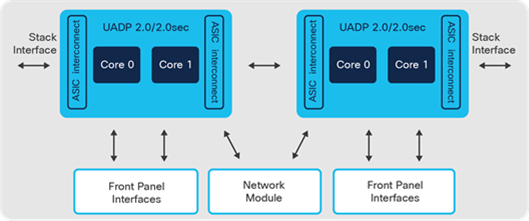
Catalyst 9300 Switch architecture
StackWise-1T, StackWise-480 and StackWise-320
Catalyst 9300 switches provide the ability to stack up to eight switches using dedicated cables on the back, combining them to operate as a single, logical switch.
Catalyst 9300X models use the same stack cables as existing Catalyst 9300 models. Catalyst 9300X switches can be stacked together and are backward-compatible with existing Catalyst 9300 models. These platforms enable flexible design options, allowing for a mix of 10/25G fiber and copper models in the same stack.
Note: Stacking between Catalyst 9300/9300X and Catalyst 9300-B, Catalyst 9300L or 9300LM models is not supported.
Additional details about Cisco StackWise can be found in the chapter High Availability.
Network modules
All Catalyst 9300 switches have an optional slot for uplink network modules. The ports on these modules can be used for both uplink and downlink connectivity.
Catalyst 9300X uplink module options:
● 4x 40G/100G QSFP ports
● 2x 40G/100G QSFP ports
● 8x 10G-mGig RJ45 ports (no PoE)
● 8x 1G/10G/25G SFP28 ports
Catalyst 9300 uplink module options:
● 4x 1G RJ45 ports (10/100/1000Mbps)
● 4x 10G-mGig RJ45 ports (no PoE)
● 8x 10G SFP+ ports
● 2x 25G SFP28 ports
● 2x 40G QSFP ports
Note: The Catalyst 9300X uplink modules are only compatible with Catalyst 9300X models.
Note: Catalyst 9300 switches are compatible with Catalyst 3850 switch uplink modules. However, Catalyst 9300 switch uplink modules are not compatible with Catalyst 3850 switches.
Uplink modules are field Replaceable Units (FRU) that enable a swap of network modules without interrupting switch operations, thereby providing investment protection without compromising on availability.
Power supply and fans
Catalyst 9300 switches support dual redundant power supplies. These 80 Plus platinum-rated AC power supplies are available in 350W, 715W, 1100W and 1900W and provide maximum energy efficiency. A DC power supply variant is also available in 715W. The power supplies can be mixed in any combination, for example, AC and DC.
Catalyst 9300 switches are equipped with three field-replaceable variable speed fans to accommodate variance in temperature and altitude. These fans are operated in an N+1 redundant mode.
StackPower
Catalyst 9300 switches provide the ability to create a shared pool of power using dedicated stack power cables. In the event of power supply failure or more PoE power draw, the switch can utilize the power from the shared pool to support the extra load.
StackPower can be deployed in two modes: power-sharing and redundant mode. Additional details are provided in the chapter High Availability.
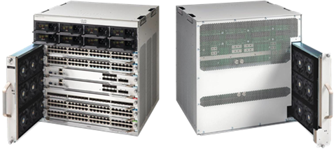
Cisco Catalyst 9400 Series switches are the leading business-critical modular enterprise Access and Distribution switching platform. Catalyst 9400 switches provide unparalleled investment protection with a flexible chassis architecture capable of supporting up to 9 Tbps of system bandwidth. They also offer unmatched power delivery for high-density PoE deployments, delivering dense 90W Cisco UPOE+ to endpoints. Catalyst 9400 switches deliver state-of-the-art High Availability with capabilities such as dual supervisors and N+1/N+N power supply redundancy. The platform is campus-optimized with an innovative dual-serviceable fan tray design, side- to-side airflow and is closet-friendly with a 16-inch depth. A single Catalyst 9400 switch can scale up to 384 access ports.
Catalyst 9400 Series Switches
Platform overview
Catalyst 9400 switches provide up to 480 Gbps per slot bandwidth. Three models offer different densities to fit different size requirements: 4-slot, 7-slot and 10-slot chassis.
All three chassis options provide dual supervisor slots for maximum availability. Each chassis is designed to support up to 720G of bandwidth between the two supervisor slots, allowing supervisors to support multiple 100G ports. With the growing need for increased PoE, the chassis has the capability of providing more than 4,800W of PoE power per slot delivering a max of 260 ports powered at 90W.
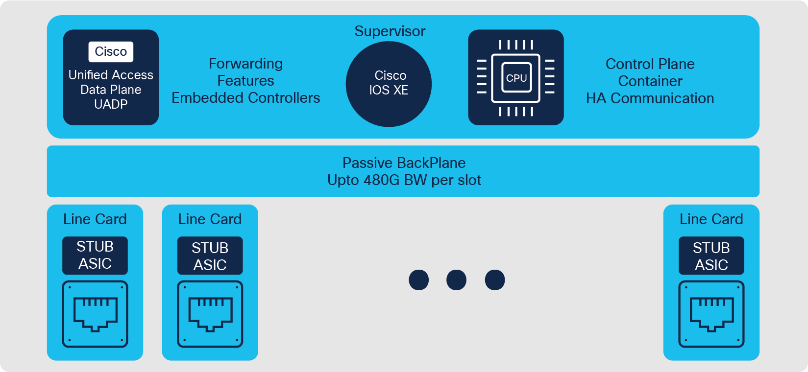
Architecture
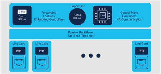
Catalyst 9400 switches are based on a centralized architecture, which means all forwarding, service and queuing are done on the supervisor, while the line cards are considered transparent, containing only stub ASICs and PHYs. The simplicity of this centralized design allows easy upgrade of bandwidth and features by just upgrading the supervisor while retaining existing line cards. This provides significant investment protection.
Catalyst 9400 Series Switch architecture
Supervisors
The Catalyst 9400 Series comes with multiple supervisor offerings that address a varied set of port speed, slot capacity and scale requirements. The supervisors are categorized based on their generation:
Catalyst 9400 Generation 2 supervisors:
● Catalyst 9400X-SUP-2
● Catalyst 9400X-SUP-2XL
Catalyst 9400 Generation 1 supervisors:
● Catalyst 9400-SUP-1
● Catalyst 9400-SUP-1XL
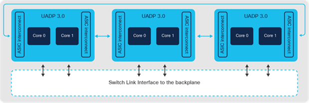
● Catalyst 9400-SUP-1XL-Y
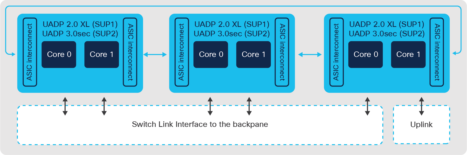
The Catalyst 9400 Gen-2 supervisors are powered by three UADP 3.0sec ASICs and a 2.3 GHz 8-core x86 CPU. Each ASIC provides up to 1.6 Tbps bandwidth, increased routing capabilities, higher buffer capacity and hardware support for IPsec and WAN MACsec. The three ASICs are interconnected with a 1.6 Tbps ASIC interconnect. UADP 3.0sec ASIC comes with 36MB unified packet buffers shared between the ASIC cores that help with improved microburst absorption. The Gen-2 supervisors support 4x 10/25G and 4x 40/100G uplink ports that support mixed combinations with overall uplink bandwidth of 400 Gbps. Catalyst 9400-SUP-2XL and 9400-SUP-2 enable 480G and 240G of per-slot bandwidth respectively, on all chassis types.
All Catalyst 9400 Gen-1 supervisors are powered by three UADP 2.0 XL ASICs and 2.4 GHz 4-core x86 CPU. The three ASICs are interconnected through a 720G ASIC interconnect. The Gen-1 supervisors have 8x SFP/SFP+ interfaces (ports 1 and 5 capable of 25G on 9400-SUP-1XL-Y) and 2x QSFP interfaces on the front provide a total of 80G uplink bandwidth shared between interfaces in various combinations. SUP-1 provides 80 Gbps of bandwidth per slot for all chassis models. SUP-1XL/1XL-Y provides 80 Gbps of bandwidth per slot in the 10-slot chassis, 120 Gbps of bandwidth per slot for the 7- slot chassis and 240 Gbps per slot for the 4-slot chassis.
All Catalyst 9400 switch Gen-1/Gen-2 supervisors come with 16 GB DRAM and 16 GB of internal flash storage. For application hosting or general-purpose storage, these switches support front-panel USB 3.0 SSD storage and additionally support onboard M2 SATA SSD up to 960 GB.
All supervisors support different ASIC templates to accommodate various deployment models as discussed in 13 - Campus Network Design. SUP-2/XL is also hardware capable of supporting customized ASIC templates that allow users to carve forwarding resources.
Catalyst 9400 switch supervisors use Switch Link Interfaces (SLIs) to connect line card stub devices through the backplane. The Catalyst 9400-SUP1 models support 10G SLI speeds for ASIC to switch backplane interconnects. The Catalyst 9400X-SUP2 models support 30G SLI speeds for Gen-2 line cards and 10G SLI speeds for Gen-1 line cards.
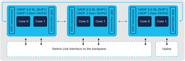
Catalyst 9400 Switch Supervisor-1XL and Supervisor-2XL architecture
Line cards
The Catalyst 9400 Series offer options of 1G, mGig (1/2.5/5/10G), Cisco PoE+, UPOE, UPOE+ and 1G/10G fiber line cards for different connectivity requirements.
● 48-port Data-only line card — all 48 ports on this module support 10/100 Mbps and 1 Gbps
● 48-port PoE+/UPOE/UPOE+ line cards — all speeds of the data-only line card with support for PoE+ (30W), UPOE (60W) and UPOE+ (90W) respectively. All 48 ports within the slot can provide the rated PoE power simultaneously.
● mGig line cards — various combinations from 100 Mbps to 10 Gbps and PoE up to 90W on RJ45 ports are supported based on requirements. The three variants are:
◦ 24 ports 10G mGig + 24 ports 1G with 60W UPOE
◦ 48 ports 5G mGig with 90W UPOE+
◦ 48 ports 10G mGig with 90W UPOE+ (Gen-2 Sup only)
● SFP/SFP+ Fiber line cards — the three variants are:
◦ 24/48 ports 1G/SFP
◦ 24 ports 10G/SFP+
◦ 48 ports 10G/SFP+ (Gen-2 Sup only)
ASIC — Line Card mapping
The diagram below illustrates the mapping of the ASICs to the line cards for the 4-slot, 7-slot and 10-slot chassis.
Table 1. Catalyst 9400 Switch ASIC — Line Card mapping
| ASIC # |
4-slot |
7-slot |
10-slot |
| UADP #1 |
Slot 1 |
Slot 2 and 7 |
Slots 1, 9 and 10 |
| UADP #2 |
Slot 4 |
Slots 1 and 5 |
Slots 2, 3 and 4 |
| UADP #3 |
Uplinks |
Slot 6 and uplinks |
Slots 7 and 8 and uplinks |
Line card oversubscription
All Gen-2 line cards (48x mGig, 48x 10G SFP+) are non-blocking, line-rate regardless of the chassis type with SUP2-XL and 2:1 oversubscribed with SUP2. Gen-1 line cards (with exception of 24x mGig + 24x 1G which is 1.1:1 oversubscribed) are line-rate with both SUP-2XL and SUP-2 on all chassis types.
The Gen-1 10G fiber and mGig line cards are oversubscribed with SUP-1, 1XL and 1XL-Y (24XS is line-rate with SUP-1XL on 4-slot chassis). All variants of 1G line cards operate at line-rate for all packet sizes.
All Gen-1 line cards get a significant bandwidth boost when operating with the Gen-2 supervisors (i.e., 3x bandwidth uplift on 10-Slot Chassis with SUP-2XL and 2x on 7-slot chassis with SUP-2XL), helping customers make the most of their existing infrastructure and investments.
Power supply
The power supplies for Catalyst 9400 switches come in small form-factor while providing high capacity and efficient output — 3200W AC with 240V input (1570W with 120V input), 2100W AC PS with 240V input (940W with 120V input) and 3200W DC PS. All AC power supplies are 80 Plus platinum-rated, providing the highest efficiency in converting AC power to DC.
The 7-slot and 10-slot chassis provide eight power supply bays while the 4-slot chassis provides four power supply bays. The Catalyst 9400 switch combines N+1 and N+N redundant options for power supplies.
Additional details are provided in the chapter High Availability.
Fan tray
The fan tray of Catalyst 9400 switches contains multiple individual fans operating in an N+1 redundant mode. Fans operate at variable speeds based on the system temperature and altitude. This makes efficient use of the power and provides lower noise levels. The field-replaceable fan tray can be replaced from the front or the rear of the chassis. This is a tremendous help with operations and reduces downtime since the cable management in a typical wiring closet could become unwieldy when removing the cables from the front of the chassis.
Catalyst 9400 Switch fan tray
Cisco Catalyst 9500 Series switches are purpose-built business-critical fixed 40G/100G/400G Core and Distribution layer switches for the campus. These switches deliver exceptional table scales, buffering capabilities, up to 12 Tbps of switching capacity and up to 8 Bpps of forwarding performance. The platform offers non-blocking 100/200/400G QSFPDD, 100G QSFP28, 40G QSFP, 25G SFP28 and 10G SFP+ switches with high port densities.
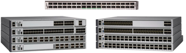
Catalyst 9500 Series Switches
Platform overview
Catalyst 9500 Series switches are 1RU fixed-configuration switches for Core, Distribution and Edge deployments. The platform supports all the foundational High Availability capabilities, including dual redundant 80Plus platinum-rated power supplies and variable-speed, high-efficiency redundant fans.
Catalyst 9500 switches are powered by either the Cisco UADP or Cisco Silicon One ASICs depending on the model. Cisco Silicon One is the first network silicon to offer switching capacity up to 25.6 Tbps in the enterprise. Catalyst 9500X powered by the Silicon One Q200 along with Catalyst 9600 SUP-2 herald the entrance of 400G into the campus Core. The architecture of both ASICs are similar but differ in switching capacity, port density, port speeds, buffering capability and forwarding scalability.
Different models offer a variety of connectivity and scale. These can be organized into various configurations of QSFP or SFP fiber options:
Note: Catalyst 9500X models with Silicon One Q200 leverage a new 800 Gbps PHY with built-in hardware encryption, IEEE 1588 time-stamping, as well as standard electrical and optical physical conversion.
● 400G QSFPDD — Catalyst 9500X (Silicon One Q200 ASIC) switch with 28x 40/100G ports + 8x 40/100/200/400G ports
● 100G QSFP28 — Catalyst 9500 high-performance (UADP 3.0) switch with 32x 40/100GE ports
● 40/100G QSFP28 — Catalyst 9500 high-performance (UADP 3.0) switch with 32x 40GE or 16x 100G ports
● 40G QSFP — Catalyst 9500 (UADP 2.0 XL) switch with 24x 40GE ports, Catalyst 9500 (UADP 2.0 XL) switch with 12x 40G ports
● 10/25G SFP28 — Catalyst 9500 high-performance (UADP 3.0) switch with 48x 25GE + 4x40/100 GE ports, Catalyst 9500 high-performance (UADP 3.0) switch with 24x 25GE + 4x40/100 GE ports
● 10G SFP+ — Catalyst 9500 (UADP 2.0 XL) switch with 40x 1/10GE ports, Catalyst 9500 (UADP 2.0 XL) switch with 16x 1/10GE ports
Architecture
Catalyst 9500 switches operate at line-rate and offer configurable system resources to optimize support for specific features.
The switch architecture consists of three main components:
● ASIC
● x86 CPU complex
● ASIC interconnect
ASIC
Cisco UADP 2.0 XL ASIC is built using 28-nanometer technology with two cores, capable of supporting up to 240 Gbps with a maximum forwarding capacity of 375 Mpps.
Cisco UADP 3.0 ASIC is built on 16-nanometer technology using two cores, capable of supporting up to 1.6 Tbps with a maximum forwarding capacity of 1 Bpps.
Cisco Silicon One Q200 ASIC is built on 7-nanometer technology using six slices, capable of supporting up to 12.8 Tbps, with a maximum forwarding capacity of up to 8 Bpps. The Silicon One Q200 ASIC features 80 MB of dedicated low latency buffers and 8 GB of High Bandwidth memory. Catalyst 9500X models with Silicon One Q200 also introduce 400G into the enterprise.
X86 CPU complex
Catalyst 9500 switches come with a 2.4 GHz x86 4-core CPU and 16 GB DRAM, while the Catalyst 9500X Switches come equipped with a 2.4 GHz x86 8-core CPU and 32 GB DRAM. In addition to 16GB of onboard flash storage, all models support up to 960GB USB 3.0 SSD drive for general-purpose storage and application hosting.
ASIC interconnect
Catalyst 9500 switches with Cisco UADP use high-speed ASIC interconnect links for inter-ASIC communication. UADP 2.0 XL has up to 720 Gbps (360 Gbps full-duplex) of interconnect bandwidth and UADP 3.0 has up to 1.6 Tbps (800 Gbps full-duplex). Packets destined to local ports within the ASIC do not use ASIC interconnect links.
Note: Models using Silicon One Q200, with 25.6 Tbps (12.8 Tbps full-duplex) of forwarding capacity, all Silicon One Q200 models can be powered with a single ASIC, thus eliminating the need for interconnects.
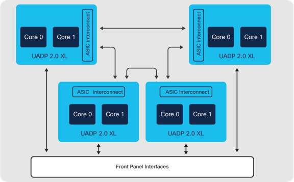
Cisco Catalyst 9500 Switch block diagram — Cisco UADP 2.0 XL
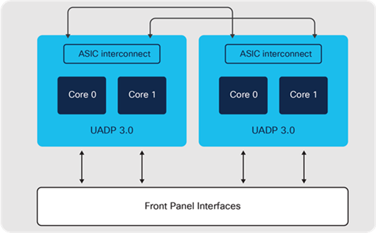
Cisco Catalyst 9500 high-performance switch block diagram — Cisco UADP 3.0
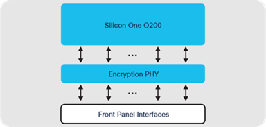
Cisco Catalyst 9500X switch block diagram — Cisco Silicon One Q200
Network modules
Only the Catalyst 9500 UADP 2.0 XL models support uplink modules. There are two variants of uplink modules that can be used to provide connectivity to an uplink switch and be used to connect hosts.
● 8x 10G SFP ports
● 2x 40G QSFP ports
Uplink modules are field-replaceable and can be swapped without interrupting switch operations, thereby providing investment protection without compromising availability.
Power supply
Catalyst 9500 switches support up to two AC 80 Plus platinum-rated or DC small form- factor power supply units: 650W AC, 930W DC, 950W AC/DC, 1500W AC/DC and 1600W AC/DC. Power supplies can be installed in the following combinations: two AC, two DC or an AC and DC combination. The power supplies work together in a redundant (1:1) load-sharing mode, in which each power supply operates at approximately 50 percent of its capacity. In case of power supply failure, the other power supply can provide power for the entire system.
Fans and fan tray
Catalyst 9500 Series switches have up to six variable speed independent fan units or dual fan trays depending on the SKU. Each fan operates at variable speeds to accommodate variance in temperature and altitude.
Catalyst 9500X switches feature two sets of six variable speed independent fan units to support reversible airflow, an important requirement enabling customers to delineate hot and cold aisles in their environment, for optimal cooling. One type is for port-side intake fans and the other type is for port-side exhaust fans.
The Catalyst 9500 Series switch can accommodate a failure of up to one individual fan or fan tray.
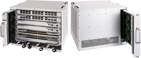
Cisco Catalyst 9600 Series switches are leading business-critical modular enterprise campus Core, Distribution and Edge platforms. The Catalyst 9606R chassis supports a switching capacity of up to 25.6 Tbps. Catalyst 9600 switches provide high port densities that fit diverse campus needs, from 1G to 400G non-blocking speeds. The platform delivers High Availability with field-replaceable dual supervisors, redundant power supplies and fans. The platform is campus-optimized with an innovative dual- serviceable fan tray design, side-to-side airflow and is closet-friendly with about 16- inch depth. A single Catalyst 9600 switch can scale up to 192 core ports.
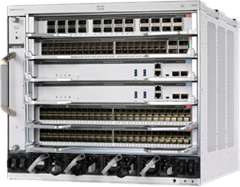
Cisco Catalyst 9606R chassis
Platform overview
Catalyst 9606R is a 6-slot chassis, with two middle slots dedicated for the supervisors and four slots dedicated for the line cards. Each line card slot has a dedicated total bandwidth of up to 6.4 Tbps (3.2 Tbps full-duplex). The Catalyst 9606R chassis can provide up to 32x 400G (QSFPDD) or 128 x 40G/100G (QSFP) or 192 x 1G/10G/25G (SFP) ports.
Architecture
Catalyst 9600 switches are based on a centralized architecture. The supervisor does all forwarding, security and queueing, while the line cards are considered transparent, containing only PHYs and control logic. The simplicity of this centralized design allows easy upgrade of features and additional bandwidth, by upgrading the supervisor while keeping the existing line cards. The centralized architecture and transparent line card combination also provides uninterrupted supervisor switchover as the foundation for In-Service Software Upgrade (ISSU).
Catalyst 9600 Series Switching architecture
Supervisors
Catalyst 9600 comes with multiple supervisor offerings that address a varied set of port speed, slot capacity and scale requirements. The supervisors are categorized based on their generation:
Catalyst 9600 Generation 2 supervisor:
● Catalyst 9600X-SUP-2
Catalyst 9600 Generation 1 supervisor:
● Catalyst 9600-SUP-1
The Catalyst 9600 Gen-1 Supervisor is powered by three UADP 3.0 ASICs, 2.0 GHz x86 8-core CPU, 16GB DRAM and 16 GB of internal flash storage. Each ASIC provides up to 1.6 Tbps bandwidth. The three ASICs are interconnected with a 3.2 Tbps ASIC interconnect. The Catalyst 9600 Gen-1 Supervisor provides 2.4 Tbps (1.2 Tbps full- duplex) of bandwidth per slot for all the line card slots.
Catalyst 9600 Switch Supervisor-1 architecture
The Catalyst 9600 Gen-2 supervisor introduces the Cisco Silicon One Q200 to the Enterprise Modular Core family, delivering the full potential of the Catalyst 9600 chassis with 6.4 Tbps (3.2 Tbps full-duplex) bandwidth per slot for all the line card slots, for a total of 25.6 Tbps switching bandwidth. The Gen-2 supervisor has a 2.7 GHz x86 8- core CPU, 32 GB DRAM and 16 GB of internal flash storage. New Line cards unlock the full potential of the new supervisor, while existing line cards get a 2x bandwidth boost with a supervisor upgrade, delivering unmatched value and investment protection.
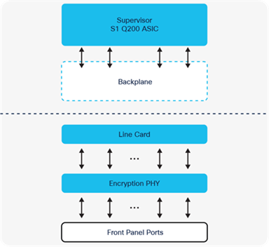
Catalyst 9600X Switch - Supervisor-2 and LC diagram
Both Gen-1 and Gen-2 supervisors support up to 960GB M2 SATA SSD options for application hosting or general-purpose storage.
Line cards
Catalyst 9600 switches offer five types of line cards for different connectivity requirements. Catalyst 9600 line cards can be leveraged for both uplink and downlink connectivity, including the new Gen-2 combo (SFP and QSFP) line cards that provide 100/200/400G uplink ports.
● Gen-2 Fiber Combo line card:
◦ With SUP-2: 40x 10/25/50G SFP56, 2x 40/100/200G QSFP56 uplinks and 2x 40/100/200/400G QSFPDD uplinks
◦ With SUP-1: 40x 1/10/25G SFP and 2x 40/100G QSFP Uplinks
Note: Gen-2 line cards leverage a new 800 Gbps PHY with built-in hardware encryption, IEEE 1588 time-stamping, as well as standard electrical and optical physical conversion.
● Gen-1 Fiber QSFP line card:
◦ 24-port QSFP28 line card
◦ With SUP-2: 24x 40/100G
◦ With SUP-1: 24x 40G or 12x 100G
● Gen-1 Fiber SFP line cards:
◦ 48-port SFP56 line card
◦ With SUP-2, 48x 10/25/50G
◦ With SUP-1: 48x 1/10/25G
◦ 48-port SFP line card
◦ 48x 1G fiber (only supported on SUP-1)
● Gen-1 Copper mGig line card:
◦ 48-port RJ45 copper
◦ With SUP-2: 48x 10G ports
◦ With SUP-1: 48x 100M/1/2.5/5/10G ports
Note: Gen-1 line cards leverage a PHY without hardware encryption. When operating with the Gen-2 supervisor, hardware encryption is not supported.
Power supply
The power supplies for Catalyst 9600 switches come in a small form factor while providing high capacity and efficient output. Catalyst 9600 switches support up to four 80 Plus platinum-rated AC or DC power supply units of 2kW (AC and DC) and 3kW (AC). The platform supports both combined and N+1 redundant modes.
Additional details are provided in the High Availability chapter 5 – High Availability.
Fans and fan tray
Catalyst 9600 Series switches contain a single fan tray with multiple individual fans operating in an N+1 redundant mode. The fans operate at variable speeds based on the system temperature and altitude. This makes efficient use of the power and provides a reduced noise level. The fan tray on Catalyst 9600 switches can be replaced from the front or the rear of the chassis. This is a tremendous help with operations and reduces downtime since the cable management in a typical wiring closet could make it unwieldy to remove the cables from the front of the chassis to service the fan tray.
Catalyst 9600 Series Switch fan tray
ASICs — the power of programmable silicon
An Application-Specific Integrated Circuit (ASIC) is a custom silicon microchip designed for a specific task such as forwarding network packets, rather than for general-purpose processing such as a CPU.
In a network switch, an ASIC handles packet recognition and Layer 2/Layer 3 processing at extremely high speeds (hundreds of Gigabits per second, trending towards Terabits per second). In addition to this, an ASIC also handles a rich set of network services, including prioritization with QoS, traffic filtering and enforcement with ACLs, segmentation with VRFs and SGTs, accounting with NetFlow and many more.
ASIC microchips are built using a process that is designated by its minimum feature size, for example, 7-nanometer technology. This translates to the size of various components used, including transistors and memory. The three main reasons for driving towards these smaller ASICs are:
● Increased speed, as electrons have shorter distances to travel
● Lower power consumption and more efficiency, with less energy wasted as heat
● Lower cost, by improving the yield (number per wafer) and quality of chips
Modern ASICs are developed with several technologies that range from 45 nm to as small as 7 nm. Newer ASICs are also packaged with multiple additional memory modules to achieve deeper buffers and scale of lookup tables.
Why do we need ASICs?
A general-purpose CPU is too slow for forwarding networking traffic. While a general- purpose CPU might be fast at running random access applications on a laptop or server, processing and forwarding network traffic is a different matter. Traffic handling requires constant lookups against large memory tables, including L2 for MAC addresses, L3 for IP routes, L4 for ACLs, Security and QoS.
In a general-purpose CPU, these tables are held in off-chip memories and incur significant performance losses for frequent access. There are also limited data paths and buffers to handle packets that are being processed at millions or billions of packets per second. Once packets have been received and queued, the CPU must perform the actual processing functions of finding destination ports and rewriting packet formats. For these reasons, a general-purpose CPU is not well-suited for network processing.
| The bottom line |
| CPUs are flexible but slow. ASICs are necessary to meet the requirements of enterprise networks. |
The following sections examine traditional and programmable network ASICs central to how a switch operates and forms the foundation of the enterprise network and is capable of handling current and future network requirements.
Traditional ASICs
Many different ASICs have been used in Cisco switches and routers over the years. Each of these were designed and developed for the specific features, speed and scale needed for different roles in the campus network.
This class of networking ASICs are known as fixed ASICs. All aspects of these ASICs (behavior, speed, scale, etc.) are hard-wired (fixed) into them as part of the manufacturing process and cannot be changed without creating a new version of the ASIC.
Another reason they are called fixed ASICs is their processing behavior. As the name suggests, all incoming packets are subject to a fixed series of steps, known as a processing pipeline. A typical fixed processing pipeline’s stages are similar to the following:
1. Parse incoming packets (examine headers).
2. Layer 2 processing (e.g., MAC lookup).
3. Layer 3 processing (e.g., IP lookup).
4. Policy processing (e.g., ACL lookup).
5. Packet rewrite and traffic counters.
6. Queue scheduling and transmission.
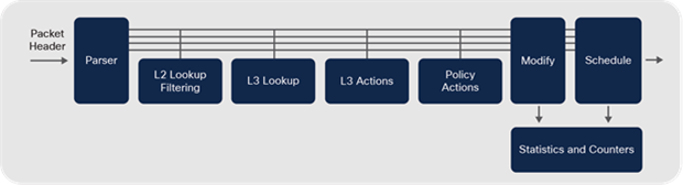
Traditional ASIC — processing pipeline
Fixed ASICs are very cost-effective and efficient but are not flexible or adaptable. They are only able to handle the types of packets that the chip is hard-wired to process.
Network and protocol evolution
Why do ASICs need to change? To provide an example, the ASIC in Catalyst 3750 can only forward IPv4 and IPv6 packets in hardware. It was designed before VXLAN was developed, and since it is a fixed ASIC, it cannot handle VXLAN in hardware. An entirely new ASIC is needed for this purpose.
This lack of flexibility may have been acceptable when networks, and related protocols, did not change much. In the new era of networking, however, everything is software- defined, with ever-evolving protocols and scale requirements. This requires ASICs to support new packet formats and encapsulations such as VXLAN-GPO, GPE and NSH.
| The bottom line |
| Traditional fixed ASICs are not conducive to the demands of the new Software-Defined world. |
Programmable ASICs
How do we get the best of both worlds? How do we get the speed we need for Gigabits or Terabits of bandwidth and deliver the flexibility to keep pace with new network innovations? These questions led to the concept of programmable ASICs — flexible network microchips designed to adapt to new capabilities and offer the performance that modern networks demand.
Early attempts led to the development of the Field Programmable Gate Array (FPGA). These are processors with fully reprogrammable logic gates that allow changing original behavior after manufacturing. Although FPGAs do provide a level of flexibility, their use as a primary switch-forwarding engine is typically cost-prohibitive due to design, manufacturing costs, board space, heat and power considerations.
These limitations typically relegate FPGAs to a special-purpose role in most network devices. For instance, an FPGA may be used to augment the packet forwarding of a fixed ASIC for that one “special” feature the fixed chip does not have, such as providing VXLAN encapsulation not supported on the switch ASIC. But this raises the total cost of a switch, using combined FPGA and ASIC designs to achieve flexibility.
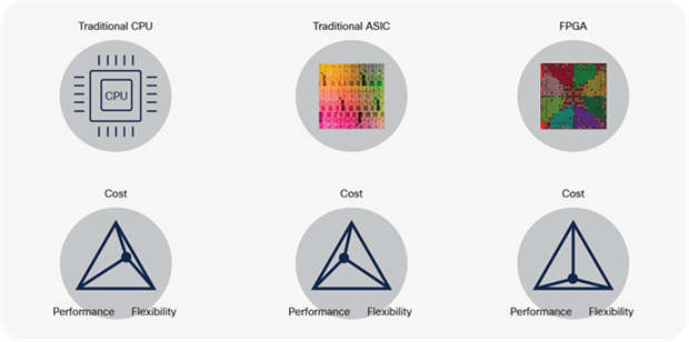
Traditional CPUs, ASICs and FPGA
| The bottom line |
| CPUs are flexible and inexpensive but do not scale for high-speed forwarding. Fixed ASICs are fast and scalable, but inflexible. FPGAs are flexible and scalable, but expensive. |
To summarize, programmable ASICs should offer:
● A flexible processing pipeline
● An option to use deep or shallow packet buffers
● An option to scale lookup tables (on-die or on-package memories)
● A single architecture that scales from low to high bandwidth, with single or multiple devices in a mesh or fabric
Cisco saw this need coming several years ago and developed the programmable Cisco Unified Access Data Plane (UADP) ASIC family.
The Cisco UADP ASIC combines the flexibility to address new and emerging networking protocols and encapsulations, with the speed of a fixed ASIC and the cost and scalability to address multiple different areas of the campus network, such as Access, Distribution, Core and more.
This approach continued with the new Cisco Silicon One ASIC family to achieve higher scale and bandwidth. The Silicon One ASIC architecture brings a scalable slice-based processing pipeline, with support for industry-standard programmable P4 microcode for datapath pipelines and support for optional on-package memories. This results in a flexible ASIC for either Switching, Routing, Data Center or Service Provider designs.
The rest of this chapter explores the Cisco UADP and Silicon One ASICs, which are at the heart of the Catalyst 9000 Family of Switches.
Cisco Programmable Switching Silicon
Flexibility in programming sets the ideal foundation for the world's most advanced switches. This enables Catalyst 9000 switches to:
● Handle new frame encapsulations, allowing new features and protocols
● Reprogram their memory tables allowing switches to adapt to changing needs
● Support multiple interface types and chassis configurations to address evolving network designs
● Maintain consistent high performance to address a growing diversity of applications
● Provide a rich, integrated set of flexible traffic handling and accounting services
Flexibility at every stage
In Cisco programmable switching silicon, almost every processing stage is made flexible and programmable, unlike a fixed-pipeline chip.
The first stage of the ASIC is a parser, whose job is to recognize packet types and headers and analyze them for further processing in the ASIC pipeline. In traditional fixed ASICs, the parser stage is fixed, making it impossible to upgrade the ASIC to recognize or process new packet types and headers in hardware.
Network Processing Unit (NPU)
This stage is the most similar to a CPU, where the network forwarding and service processing occur. Unlike fixed-processing pipelines, Cisco programmable ASICs multi- stage flexible pipelines (L2, L3 forwarding, policy, rewrite, queuing, etc.) are also completely reprogrammable via firmware microcode.
NPUs can be a single processor or multiple processors (cores) integrated into a single package to share the load and expand capacity. There is an ingress NPU pipeline to process incoming packets and an egress NPU pipeline to process outgoing packets.
Cisco’s programmable ASICs are also capable of reallocating and customizing memory resources through different configurable templates, unlike fixed ASICs where the resources are fixed to a specific stage or function.
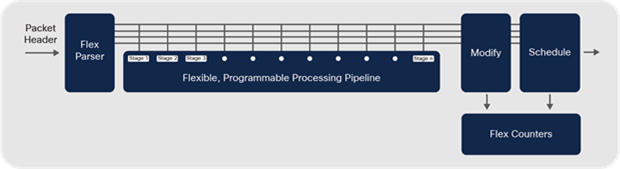
Programmable Cisco ASIC — processing pipeline and NPU
Integrated micro-engines
Certain functions executed by a Programmable ASIC may be very processing intensive. Several basic tasks are based on well-known fixed algorithms and it does not make sense to waste cycles in the ASIC pipeline. In such cases, an on-chip micro-engine is available that can process these functions in parallel, saving valuable ASIC performance.
Some examples of micro-engine functions built into the ASIC include:
● Encryption and decryption
● Fragmentation
● Packet replication
Packet recirculation
Traffic tunneling is a common requirement in modern networks. IPsec, GRE, MPLS and VXLAN are common tunneling protocols. They add an additional header outside the original packet when sending (known as encapsulation or encryption) and remove the outer header when the packet is received (known as decapsulation or decryption).
Any time packets need to be tunneled in an ASIC, the original packet may need to be processed more than once, to add or remove additional headers. This is known as recirculation.
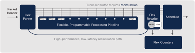
Programmable Cisco ASIC — packet recirculation
The bandwidth available for recirculation is flexible, meaning recirculation can also use the spare bandwidth not currently being used by the front-panel ports. When tunneling is required, the impact on forwarding performance is minimal. A packet can be recirculated multiple times, but only two or three passes are normally required.
ASIC Interconnects
In some cases, based on required port types and densities, a switch may be built around a single ASIC or multiple ASICs interconnected.
For this purpose, dedicated Input/Outputs (I/O) on the ASIC can be used to interconnect multiple ASICs together in either a point-to-point (mesh or fabric) or a ring (stack), expanding the total scale of the system. These interconnects can be within the switch or use external cabling outside the switch.
CPU Interconnects
Enterprise networks are now dealing with massive volumes of data and there is a need to collect and analyze this data to respond faster and deliver insightful context. Traditional approaches using remote servers will no longer work.
Edge computing (enabled by Application Hosting) can greatly reduce the data sent to the cloud or a remote server, by collecting and analyzing the data at the Edge and making decisions locally to reduce the latency and bandwidth of the network. To meet this requirement, ASICs should provide dedicated links for application traffic from the ASIC to the CPU, to maximize the performance of such hosted applications.
Cisco UADP and Silicon One ASICs support application port(s) for speeds up to 10 Gbps each, that directly map front-panel ports to the CPU. For more details on container networking and how it can be utilized, refer to Application Hosting.
Programming ASICs with microcode
Cisco IOS XE is a multi-layered operating system. Some lower software layers are closely associated with hardware. Meanwhile, hardware drivers and infrastructure pieces of the software (known as microcode) directly interact with the hardware. This microcode layer of the software programs the ASIC. Refer to the chapter Cisco IOS XE for more details about the software architecture.
The microcode for programming the ASIC is included in the Cisco IOS XE image. Any changes to the microcode are included with the image that runs on a Catalyst 9000 switch. Microcode upgrades allow flexible ASIC resources allocation.
Programmable ASICs in the Catalyst 9000 Switch Family
The Catalyst 9000 family consists of two main variants of programmable ASICs
● Cisco UADP family — UADP is a feature-rich ASIC primarily used on the platforms positioned as Access, Distribution and Core layers of the enterprise campus, where the Internet routing scale is not required.
● Cisco Silicon One family — Silicon One is a high-performance ASIC, primarily used on platforms positioned for Core and (ISP/WAN) Edge, where higher scale and buffer memory is essential.
Now, let us deep dive into each of the ASIC families in detail.
The Cisco UADP ASIC family began in 2013 with UADP 1.0 and has progressed significantly in terms of technology and has incorporated more transistors and memories with each generation. Each additional transistor means that additional performance, scalability, features and functionalities can be built into the ASIC.
The Cisco Silicon One ASIC family began in 2017 with Q200, with the acquisition of Leaba Networks, and represents a new class of programmable multi-slice ASICs designed for Service Provider, Enterprise and Data Center Core networks.
Catalyst 9000 switches are built on the next generations of UADP (UADP 2.0 and 3.0) and Silicon One (Q200) ASICs.
Cisco UADP 2.0
The Cisco UADP 2.0 is a dual-core 28 nm ASIC providing aggregate bandwidth up to 240 Gbps (full-duplex). UADP 2.0 also has large shared, flexible memory tables that can be reprogrammed using SDM templates, giving the option to deploy the same device in multiple network areas, as discussed in Campus Network Design.
Cisco UADP 2.0 ASICs have four variants: UADP 2.0, 2.0sec, 2.0 XL and 2.0 mini. Both 2.0 and 2.0 XL have the same architecture, but the UADP 2.0 bandwidth, table scale and overall performance have been optimized for business-critical access layer switches. Cisco UADP 2.0sec has a similar architecture as UADP 2.0, but provides higher bandwidth for front-panel ports and stacking, as well as 100G of hardware encryption for IP security.
Cisco UADP 2.0 XL has been optimized for Modular Access and Distribution layer switches. It has larger memory table sizes (hence the XL designation) with greater aggregate bandwidth and overall performance for port speeds and density needed for these roles. UADP 2.0 XL also has inter-ASIC connectivity using dual datapaths of 720 Gbps, to support platforms where multiple ASICs are required. The first-generation Catalyst 9500 Series switches and the Catalyst 9400 Series Supervisor-1 and 1XL use UADP 2.0 XL.
Cisco UADP 2.0 mini has a modified single-core architecture with an integrated quad- core ARM CPU and bandwidth, table scale, overall performance and power consumption have been optimized for simple access layer switches.
Table 2. Cisco UADP 2.0 product comparison
|
|
UADP 2.0 mini Catalyst 9200L/ Catalyst 9200 |
UADP 2.0 Catalyst 9300 |
UADP 2.0sec Catalyst 9300X |
UADP 2.0 XL Catalyst 9400 SUP1/SUP1-XL Catalyst 9500 |
| MAC entries |
16K/32K |
32K |
32K |
64K |
| Host routes IPv4 |
8K/10K |
24K |
24K |
48K |
| LPM routes IPv4 |
3K/4K |
8K |
15K |
64K |
| LPM routes IPv6 |
1.5K/2K |
4K |
7.5K |
32K |
| Multicast routes |
1K |
8K |
8K |
16K |
| QoS entries |
1K |
5K |
4K |
18K |
| ACL entries |
1K |
5K |
8K |
18K |
| NetFlow entries (per ASIC) |
16K |
64K |
64K |
128K |
| SGT entries |
2K |
8K |
8K |
16K |
| Buffers |
6 MB |
16 MB |
16 MB |
32 MB |
| Inter-ASIC bandwidth |
80 Gbps |
240 Gbps |
540 Gbps |
720 Gbps |
Cisco UADP 3.0
The Cisco UADP 3.0 is a dual-core 16 nm ASIC that provides a significant increase of aggregate bandwidth of up to 1.6 Tbps (full-duplex). UADP 3.0 is designed to address the requirements of new interface speeds of 25G and 100G. The increased bandwidth and performance make it the ideal ASIC for campus Core and Distribution layer switches.
Cisco UADP 3.0 has larger memory tables and greater reprogramming flexibility, with larger shared packet buffers (36MB) to support interface speed increases. It also has double-wide memory table sizes to store both IPv4 (32-bit) and IPv6 (128-bit) addresses in a single entry thus allowing the same scale for IPv4 and IPv6 networks.
Cisco UADP 3.0sec has a similar architecture to UADP 3.0 with the main addition of the 100G hardware encryption capability and extra scale for IP security. Catalyst 9400X models with Supervisor 2 and 2XL use the UADP 3.0sec ASIC.
Table 3. Cisco UADP 3.0 product comparison
|
|
UADP 3.0 Catalyst 9500 High Performance Catalyst 9600 SUP1 |
UADP 3.0sec Catalyst 9400 SUP2/2XL |
| MAC entries |
up to 128K |
up to 128K |
| Host routes (IPv4/v6) |
up to 256K/256K |
up to 256K/256K |
| LPM routes (IPv4/v6) |
up to 256K/256K |
up to 256K/256K |
| Multicast routes (IPv4/v6) |
up to 32K/32K |
up to 32K/32K |
| QoS entries |
up to 16K |
up to 16K |
| ACL entries |
up to 27K |
up to 27K |
| NetFlow entries (per ASIC) |
up to 128K |
up to 128K |
| SGT entries |
up to 64K |
up to 64K |
| Buffers |
36 MB |
36 MB |
| Inter-ASIC bandwidth |
up to 1600 Gbps |
up to 1600 Gbps |
For more details about the supported combination of features and scales, please refer to the configuration guide: cisco.com/go/sdmtemplates.
Cisco Silicon One Q200
The Cisco Silicon One architecture enables a single multi-slice ASIC to be used in both switching or routing platforms, to achieve higher flexibility, performance and better power efficiency. There are several variants of Silicon One ASICs depending on the bandwidth and buffer requirements, including the Q200 that is used on Catalyst 9000 switches.
The Q200 is a six-slice 7 nm ASIC with an overall throughput of 12.8 Tbps (full-duplex). The smaller size and high bandwidth per ASIC helps achieve a better than 40% improvement in power consumption for the same bandwidth compared to similar ASICs. In addition to 80 MB of on-die Shared Memory System (SMS) buffers, the on- package High Bandwidth Memory (HBM) of 8 GB allows deep buffers and expands the L3 table scale. Silicon One ASICs also support standardized P4 programmable microcode language that allows flexibility in processing pipeline programming.
The Q200 ASIC supports flexible input and output (I/O) speeds enabling interfaces to operate from 10 Gbps up to 400 Gbps.
Table 4. Cisco Silicon One Q200 product details
|
|
Cisco Silicon One Q200 Catalyst 9500X Catalyst 9600X SUP2 |
| MAC entries |
up to 256K |
| Host routes IPv4/v6 |
up to 256K/128K |
| LPM routes IPv4/v6 |
up to 2M/1M |
| Multicast routes IPv4/v6 |
up to 32K/16K |
| QoS entries |
up to 10K |
| ACL entries |
up to 10K |
| SGT entries |
up to 32K |
| MPLS labels |
up to 512k |
| Buffers (SMS/HBM) |
80 MB/8 GB |
Additional details and block diagrams are available at:
Catalyst 9500 Series — cisco.com/go/cat9500architecture
Catalyst 9600 Series — cisco.com/go/cat9600architecture
Catalyst 9000 switches use a Switching Database Manager (SDM) template to define how ASIC memory resources (MAC and IP addresses, Security and QOS ACLs, FNF cache entries, etc.) should be allocated. Cisco IOS XE allows the user to define the SDM template to be used, enabling the switch to be used in different roles in the network.
Both Cisco UADP and Silicon One ASICs support the use of different predefined SDM templates. These predefined SDM templates are designed to optimize ASIC resources for a specific role.
There are 4 predefined SDM templates:
● Access — maximized for L2 MAC unicast and multicast switching
● Distribution — balanced for L2 MAC, L3 IP and security
● Core — maximized for L3 unicast and multicast routing
● NAT — maximized for L3 and NAT in core/edge deployments
In addition to predefined templates, both UADP 3.0 and Silicon One Q200 also support user-customizable SDM templates.
Table 5. Catalyst 9000 family SDM template support
|
|
Access |
Distribution |
Core |
NAT |
Customizable |
| Catalyst 9200 |
✓ |
N/A |
N/A |
N/A |
N/A |
| Catalyst 9300 |
✓ |
N/A |
N/A |
N/A |
N/A |
| Catalyst 9300X |
✓ |
N/A |
N/A |
N/A |
N/A |
| Catalyst 9400 - SUP1 |
✓ |
N/A |
N/A |
N/A |
N/A |
| Catalyst 9400 - SUP1XL/Y |
✓ |
N/A |
✓ |
✓ |
N/A |
| Catalyst 9400X - SUP2/XL |
✓ |
HW capable |
HW capable |
HW capable |
HW capable |
| Catalyst 9500 |
N/A |
✓ |
✓ |
✓ |
N/A |
| Catalyst 9500 High- Performance |
N/A |
✓ |
✓ |
✓ |
✓ |
| Catalyst 9500X |
N/A |
N/A |
✓ |
N/A |
✓ |
| Catalyst 9600 - SUP1 |
N/A |
✓ |
✓ |
✓ |
✓ |
| Catalyst 9600X - SUP2 |
N/A |
N/A |
✓ |
N/A |
✓ |
For more details of SDM templates, see: cisco.com/go/sdmtemplates
The history of the Cisco Internetwork Operating System (IOS) goes back to Cisco’s first product, the AGS multi-protocol router launched in 1986. At the time, Cisco IOS was still a monolithic (non-modular) operating system. It was one of the very first network operating systems in the industry and has evolved as the industry has evolved, with thousands of features added in the last 30 years.
Over time, variations of Cisco IOS software have been created to accommodate the expanding Cisco portfolio of switches, routers, access points and wireless controllers, including new operating systems for the data center (Cisco NX-OS) and service providers (Cisco IOS XR).
Cisco IOS has evolved into IOS XE, designed to restructure the monolithic code infrastructure of IOS into a modular and modern software architecture. With IOS XE, the OS is divided into multiple components to achieve modularity and portability of features. A low-level Linux kernel was introduced to provide CPU load-balancing, memory management and enhance hardware resource management.
Cisco IOS now runs as a modular process on top of the Linux kernel (known as Cisco IOSd). This approach allows other modular functions to be introduced, such as Wireshark and applications running in containers.
Cisco IOS XE is continually evolving. With new applications appearing, the established models for configuration and monitoring, such as CLI and SNMP, are slowly being replaced by standardized APIs based on data models.
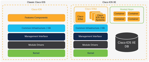
Classic Cisco IOS to Cisco IOS XE comparison
The latest Cisco IOS XE software addresses several key customer needs:
● A unified Operating System for enterprise networks
● A secure, trustworthy OS to protect the network
● Modularity and High Availability
● Programmability and automation
● Rapid introduction of new features and technologies
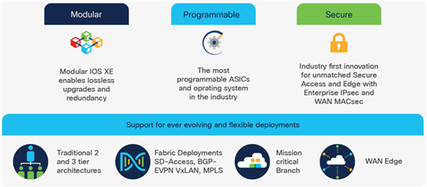
IOS XE: Open and flexible network operating system
This unified OS software release brings multiple advantages:
● Consistent experience across platforms
● Portability between core and access platforms
● Fewer software images to manage
● Faster certification of software features
● Ability to run any feature anywhere
Catalyst 9000 switches have taken this one step further: the entire Catalyst 9000 Family of Switches runs on the same IOS XE codebase and same image. This provides for faster delivery of innovation and improved code quality, along with consistent feature behavior, bringing simplification of software image selection, deployment and use.
Note: Catalyst 9200 Series uses a different binary based on a lightweight version of IOS XE known as Cisco IOS XE Lite.
Cisco IOS XE is built on top of Linux OS. Various components of IOS XE run as individual sub-processes and share a common information database that stores the operational state of all the features in a consistent format. This modular OS architecture not only provides key features such as process restartability and patching but also enables the use of containers for hosting Cisco and third-party applications.
The Cisco IOS XE architecture has three significant enhancements:
● Cisco IOS modularity
● Cisco IOS XE database
● Application hosting
Modular OS
With Cisco IOS XE, the classic Cisco IOS code is divided into multiple modules. The majority of the base IOS code is hosted as a daemon (Cisco IOSd) which comprises traditional IOS features and components such as switching and routing protocols.
Cisco IOSd is further divided into multiple IOS subsystems, providing the capability to service one of the sub-systems without affecting the remaining Cisco IOSd code. Cisco IOSd also provides resiliency in case of individual subsystem failure as it is completely segmented from the remaining IOS code.
This particular OS modularization helps with updating Cisco IOS by applying software patches (known as software maintenance upgrades or SMUs), without affecting the running system.
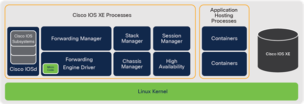
Modular Cisco IOS XE
Cisco IOS XE database
Previously, Cisco IOS stored all switching and routing protocol states and related forwarding information in a distributed manner. The process state information was stored in many different parts of memory, in different formats, making it sub-optimal and non-consumable outside the switch.
The Cisco IOS XE architecture decouples the data from the code. A new feature in the OS is the Cisco IOS XE database which stores the configuration and operational state of the system. The data is stored in a standard model-based format. Major benefits of storing the state information in a centralized database include being able to share information easily between different components of IOS XE.
This standard Cisco IOS XE database makes system data easier to express externally as data models. IOS XE has an interface to convert the database into common data models such as YANG and provides efficient export using Model-Driven Telemetry (MDT). MDT is explained in greater detail in the chapter Network management.
Application hosting
Cisco IOS XE supports container hosting capability on the Catalyst 9000 Family of Switches. Please refer to the chapter Application hosting.
Cisco IOS XE Lite
With Cisco IOS XE being modular, certain feature sets not applicable on a simple branch device (such as BGP, MPLS or ETA) can be removed from operating system libraries. Cisco IOSd and bash were optimized to further reduce the footprint in Cisco IOS XE Lite. Even with a 50% decrease in image size, essential benefits of Cisco IOS XE are maintained and all modern features such as streaming telemetry, failure isolation and status recovery remain.
With the ever-changing modern software-defined environment, it is imperative that the OS software foundation of the Catalyst 9000 Family of Switches is open, easy to use, flexible and secure. Cisco IOS XE is an open and modular operating system, common across multiple enterprise network products and brings many benefits to customers. The modularity, standard database, object-based models and containers of IOS XE provide key capabilities that help IT and OT with operational tasks and reduce operational costs.
Benefits include a single software image across the Catalyst 9000 Family of Switches, simplifying network administration and improving software lifecycle management. This provides a consistent format and experience, with consistent provisioning across all devices. A "run any feature anywhere" approach means that features can be ported very quickly to other platforms. Recent examples of software imported to Catalyst platforms in a short time are MPLS, NAT and NBAR2.
Some additional key benefits include Cisco IOS XE install mode, a new WebUI and Cisco Trustworthy Solutions.
Cisco IOS XE install mode consumes less memory because the packages are already extracted from the .bin file. With install mode, the Catalyst 9000 switch boots Cisco IOS faster compared to bundle mode. Install mode is the recommended mode, and advanced High Availability features such as ISSU, patching and xFSU are only supported with install mode.
Cisco IOS XE WebUI was introduced to help customers navigate the device through a standard Web browser. Users can perform simple configurations, troubleshooting and monitor high levels of CPU and memory utilization. Users can also configure advanced features such as AVC to monitor applications.
Cisco built Catalyst 9000 switches to be trustworthy and help prevent attacks against a network. As a Trustworthy solution, Catalyst 9000 switches verify the authenticity of the platform, prevent malicious code execution, establish run-time defenses and secure communication. For more information on Trustworthy Solutions, please refer to the chapter Security and identity.
Building Campus networks with redundancy, also known as High Availability (HA) is critical to ensuring business continuity. Catalyst 9000 switches provide comprehensive HA across all aspects of your Campus network, from physical and infrastructure, to Layer 2 (L2) and Layer 3 (L3) processes and protocols, software upgrades and more.
This section explores these HA techniques:
● Physical redundancy — Power, Fans and Links
● Layer 2 redundancy — SSO and L2 protocols
● Layer 3 redundancy — NSF/NSR, GIR
● Infrastructure redundancy — StackWise and StackWise Virtual
● In-Service Software Upgrade — ISSU
● Software Patching — SMU
Note: Physical redundancy details are described in each platform section.
In addition to the platform-specific physical redundancy, the Catalyst 9000 Switching Family also supports protocol-level redundancy features to provide faster convergence for L2 and L3 network designs.
Layer 2 redundancy
Stateful Switch-Over (SSO)
Stateful switchover (SSO) offers minimal disruption to Layer 2 sessions for redundant device configuration. SSO replicates forwarding tables, running configuration and start-up configuration between an active and a standby switch/supervisor. If the active fails, the system immediately activates on standby.
Note there are many L2 protocols and redundancy options supported, such as STP, REP, L2 Etherchannels, etc. Specific protocol support is covered in each platform section.
Flexlink+
Flexlink is a fast and simple solution for L2 uplink redundancy, providing faster link convergence compared to Spanning Tree Protocol (STP). Flexlinks are typically configured in enterprise networks where customers do not have control over configuring devices on the other end or do not want to run STP on their devices.
Flexlink+ is based on Cisco Resilient Ethernet Protocol (REP) Edge - No Neighbor and enables the user to configure a pair of L2 interfaces (trunk ports or port channels) where one interface is configured to function as a backup to the other.
Flexlink+ is capable of VLAN load-balancing where a switch pair is configured to simultaneously forward the traffic for mutually exclusive VLANs. It also supports preemption, where the preferred ports for the VLAN set can resume the traffic forwarding upon recovery from a failure. Flexlink+ supports multicast packet transmission over a new active interface, assisting the other end to learn the source MAC address for continuity.
For more information about Flexlink+, please refer to: cisco.com/go/flexlink
Layer 3 redundancy
Nonstop Forwarding
Building on top of L2 SSO, Nonstop Forwarding (NSF) helps to suppress L3 routing flaps. Usually when a device restarts, all routing peers of that device detect that it went down and then came back up. This transition results in what is called a routing flap, which could spread across multiple routing domains. Routing flaps create routing instabilities detrimental to the overall network performance. NSF allows for the forwarding of data packets to continue along known routes while the routing protocol information is restored following a switchover. With NSF, peer devices do not experience routing flaps.
Nonstop Routing
Nonstop Routing (NSR) helps remove the NSF dependency on the peer device and instead relies on the standby switch or supervisor within the same system. The standby switch or supervisor not only maintains the traffic forwarding information using the SSO mechanism but also control plane information for routing protocols. With NSR, peer devices do not experience routing flaps.
Note: NSF or NSR should be enabled explicitly for the L3 routing protocols.
Note: There are many L3 protocols and redundancy options supported, such as BGP, OSPF, EIGRP, HSRP, VRRP, BFD, L3 EtherChannels etc. Specific protocol support is covered in each platform section.
IP Fast Reroute (IP FRR)
IP FRR aims to solve the issue of traffic blackholing from link failure in L3 networks, by pre-installing a backup path. Normally, when a local link fails, the routing protocol recomputes a new next hop for all affected IP prefixes which are then updated in the Routing Information Base (RIB) and Forwarding Information Base (FIB), which can take several seconds or even minutes.
IP FRR provides a fast route convergence of fewer than 50 msec by precomputing a Loop-Free Alternate (LFA) path for each IP prefix in the RIB. When the device is notified of the link failure, it immediately switches to the repair path to reduce the traffic loss.
Supported routing protocols such as OSPF and EIGRP leverage different mechanisms to compute the backup path.
For more information about IP Fast Reroute, please refer to: cisco.com/go/ipfrr
Graceful Insertion and Removal (GIR)
Graceful Insertion and Removal (GIR), leverages redundant paths and existing protocol convergence methods to gracefully remove a L3 routing device for software and hardware maintenance without impacting existing flows. Conversely, GIR also gracefully reinserts the device back into service when the work is complete.
GIR allows the administrator to enter an automated maintenance mode, which manipulates the routing protocol and first-hop gateway metrics of a device about to undergo maintenance, to make the device an undesired path. GIR does this by sending messages to indicate to peers that this device is no longer the best path for traffic.
Once the traffic moves away from the device, maintenance actions can be undertaken. Once the maintenance is complete, GIR returns these metrics to their former values then smoothly restores normal traffic flow.
Below is the sample routed-access topology where switch S4 is put into maintenance mode and all the traffic is diverted gracefully to the redundant path:
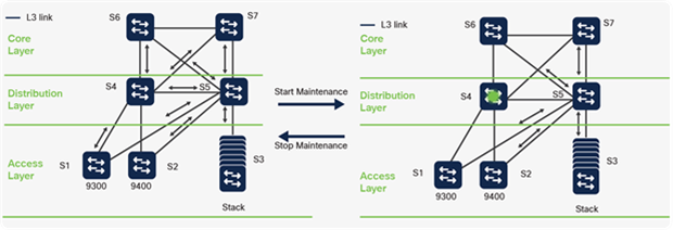
Graceful Insertion and Removal in action
Note: GIR is intended for use in the Core and Distribution layers.
Catalyst 9000 switches running Cisco IOS XE also provide system-generated snapshots to record the state of a switch before and after maintenance. Snapshots are useful for verifying that a switch is operating correctly when it returns to service. Catalyst 9000 switches also provide the flexibility to define custom maintenance profiles to set site- specific methods for performing removal or insertion.
For more information about GIR, please refer to: cisco.com/go/gir
Infrastructure redundancy
Cisco StackWise
Catalyst 9200 and 9300 Series fixed configuration switches provide stacking to expand port density, switching capacity and enable redundancy in wiring closets. Moreover, stacking delivers operational simplicity by combining multiple switches to form a single logical switch.
Cisco StackWise creates a unified control and management plane, leveraging SSO and NSF, by electing one switch in the stack as the SSO active and another switch as a SSO standby. Remaining switches become stack members. The active switch is responsible for all L2 and L3 network control processing and for synchronizing all state information with the standby switch.
Note: All switches in a stack must have the same version of Cisco IOS XE and license.
The forwarding architecture is designed to provide distributed switching across all member switches in the stack. Each switch in the stack optimizes data plane performance by utilizing its local hardware resources. This includes forwarding tasks and network services such as QoS and ACLs. Distributing stack processing delivers wire-speed performance, increases overall system resource capacity, prevents overloading of the active switch processor and optimizes stack bandwidth capacity.
Spatial Reuse
Cisco StackWise throughput doubles by employing a spatial reuse algorithm on the stack's rings. Spatial reuse is enabled by a process called destination packet-stripping. Within traditional ring architectures, packet stripping happens on the source switch (where the packet originated) and while ring members are processing a packet, no other data may be passed into the ring.
Spatial reuse, however, allows multiple flows to co-exist. Spatial reuse frees available bandwidth on the ring, as the destination switch strips the packet destined to itself, allowing the insertion of additional packets onto the ring by other stack members.
Note: Cisco StackWise ring details are described in each platform section.
For more information about Cisco StackWise, please refer to: cisco.com/go/stackwise.
StackWise Virtual
Catalyst 9400, 9500 and 9600 Series switches support StackWise Virtual, which allows the merging of two physical switches together into a single, logical switch, using front-panel Ethernet ports. The two switches operate as one and share the same configuration and forwarding state. This is analogous to the Virtual Switching System (VSS) feature in the prior generation of Catalyst switches.
Note: StackWise Virtual requires both switches to have identical hardware and software.
StackWise Virtual greatly simplifies the design of a campus network. It enables the creation of a loop-free topology, because the two switches and all links operate as one. For example, STP treats a StackWise Virtual pair as one bridge node, instead of two.
StackWise Virtual also incorporates HA features such as SSO, NSF and ISSU, which provides infrastructure-level redundancy and eliminates the need for L2 or L3 redundancy protocols such as HSRP or VRRP. It also supports Multichassis EtherChannel (MEC), which provides both link redundancy and increased bandwidth.
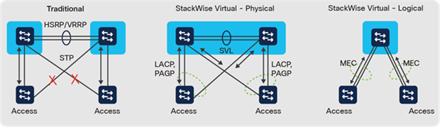
Benefits of StackWise Virtual
Within a StackWise Virtual pair, one device is designated as the SSO active virtual switch and the other is the SSO standby virtual switch. The active virtual switch manages all management and L2 and L3 control plane functions and synchronizes all state information with the standby virtual switch.
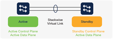
StackWise Virtual domain
From the data plane (traffic forwarding) perspective, both switches in a StackWise Virtual pair are actively forwarding traffic (active-active). They each perform local forwarding decisions and, when necessary, forward traffic to neighboring switches via L2 or L3 MEC or through L3 Equal Cost Multi-Pathing (ECMP).
StackWise Virtual components
StackWise Virtual is formed by leveraging the following components:
● StackWise Virtual Link (SVL)
● Dual-Active Detection (DAD)
● Multichassis EtherChannel (MEC)
StackWise Virtual Link (SVL)
The SVL is a vital part of forming a StackWise Virtual domain. It provides both the signaling path used for synchronizing the two switch control planes, and also serves as the data path for any traffic that needs to pass between the two switches. The SVL is a special EtherChannel and can be configured using supported 10G or higher speed interfaces.
StackWise Virtual supports up to eight interfaces to form an SVL. Cisco recommends using more than one link in an SVL for redundancy (i.e., EtherChannel), and ensuring the total SVL bandwidth is at least equal to the total uplink bandwidth, to guarantee continuity if an uplink or downlink fails.
Dual-Active Detection (DAD)
If all SVL links fail, the communication is broken between the StackWise Virtual pair. This could cause a dual-active scenario, in which both switches assume the SSO active role, causing adverse effects on both control plane and data plane. To avoid a dual- active scenario, Cisco recommends configuring DAD. DAD detects the dual-active scenario, and then disables all links on the former active virtual switch to prevent blackholing traffic.
Upon the recovery of SVL links, the disabled switch is then rebooted automatically to resolve the dual-active state. DAD can be deployed using either a dedicated link, or it may be configured to leverage enhanced Port Aggregation Protocol (ePAgP). Up to four interfaces may be configured for DAD, and Cisco recommends using more than one for redundancy.
Note: The system management (mgmt0) interface cannot be used for DAD.
Multichassis EtherChannel
Multichassis EtherChannel (MEC) simplifies the connection between StackWise Virtual switches and neighboring devices, by allowing dual-homed connections to be configured as EtherChannel links (as opposed to individual links). MEC supports both L2 or L3 EtherChannels, resulting in increased bandwidth and physical link-layer redundancy. StackWise Virtual MECs configured using mode "ON", Link Aggregation Control Protocol (LACP) or Port Aggregation Protocol (PAgP).
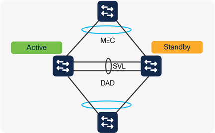
StackWise Virtual components
StackWise Virtual High Availability
In the event of a failure on the active StackWise Virtual switch, the standby switch immediately becomes active and continues forwarding traffic. StackWise Virtual leverages SSO and NSF or NSR to achieve a switchover within a sub-second interval.
In-Service Software Upgrade (ISSU)
ISSU allows customers to eliminate planned outages for full feature software upgrades. It provides upgrade and rollback of the Cisco IOS XE software without incurring an outage. ISSU is an administrative process implemented through a set of exec-level CLI commands issued in a specific order.
ISSU technology uses SSO and NSF as foundational features. While SSO synchronizes the active and standby in the same switch, using the same Cisco IOS XE image version, ISSU synchronizes active and standby using two different versions.
ISSU with StackWise Virtual
Since StackWise Virtual is based on SSO and NSF, the same principles apply for ISSU. The ISSU process in SVL configuration is similar to standalone ISSU. The main difference is an entire virtual switch will be reloaded, vs a single supervisor.
Note: During ISSU switchovers, there will be a sub-second traffic convergence.
ISSU prerequisites
Before an ISSU can be performed on a switch, the following must be verified:
● A new Cisco IOS XE image has been pre-loaded into flash
● The switch must be running in install mode
● NSF or NSR should be enabled
ISSU process
The ISSU process has five steps:
1. A user starts ISSU. The new image is expanded on both the active and standby switches.
2. The standby switch reloads with the new image.
3. The active switch performs a switchover to the standby switch, which transitions to the active role.
◦ The other switch reloads the new image, and transitions into the standby role.
4. Once the ISSU process completes successfully, the upgrade is committed.
◦ If not, then the ISSU process automatically rolls back to the previous image.
5. ISSU is completed.
The diagram below describes the ISSU process:
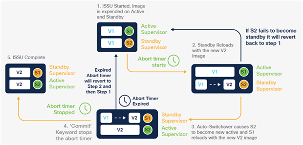
ISSU process details
Software Patching (SMU)
In a complex operating system, defects (bugs) happen. When a switch encounters a defect, it affects network behavior and, consequently, business operations. Fixing a defect can be as daunting as encountering one. Distributing new software across network infrastructure, and applying it, generally requires coordinated system downtime. After upgrade, new code must be requalified to ensure the problem is truly resolved, as well as prove that it does not introduce new issues.
Cisco IOS XE introduces patching to solve this problem. Being a modular operating system, IOS XE allows point fixes within the software, without having to upgrade the entire image. This means that defects and security vulnerabilities can be resolved without requalifying an entire new image, and in minor cases, without rebooting a switch.
In Cisco IOS XE, patching is also referred to as Software Maintenance Upgrade (SMU). When applying a SMU, the administrator first uploads the patch file to the switch. Then the patch is activated and the switch understands a new patch is available. At this point, the patch is considered active, but if necessary, the administrator can roll back by deactivating the patch and then delete the SMU from local storage. If the SMU fix is acceptable, the administrator then commits the patch, which makes it persistent across reloads.
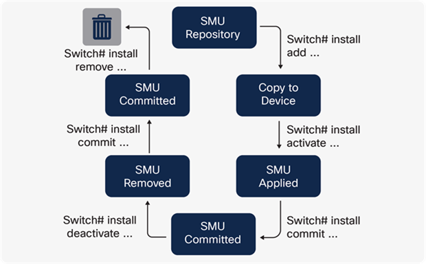
Software Maintenance Upgrade workflow
Two types of patching are available:
● Cold patching — These are typically low-level infrastructure code changes, and application of a cold patch requires a switch reload.
◦ Note Cisco IOS XE Lite on Catalyst 9200 Series switches only supports cold patching
● Hot patching — These are typical minor code changes, and hot patches do not require a system reload. Cisco IOS XE switches only need to restart the process being patched.
SMU patches can be deployed via multiple methods:
● Command Line Interface (CLI)
● YANG API
● Software Image Management (SWIM) utility on Cisco DNA Center
These options are described more in the Network Management chapter.
Catalyst 9200 Series High Availability
Catalyst 9200 Series switches deliver access layer redundancy with features such as StackWise-160/80 and infrastructure redundancy.
Catalyst 9200 Series
Catalyst 9200 and Catalyst 9200L switches with Cisco IOS XE Lite support Cisco StackWise stacking for up to eight members, but mixed stacking between them is not supported. They are physically connected in a ring topology with dedicated stacking cables connected at the back of each switch.
Catalyst 9200 Series switch stacks deliver deterministic non-blocking switching performance for up to 416 ports.
StackWise-160/80 architecture
Catalyst 9200 Series switches support StackWise-160 with up to 160 Gbps stack bandwidth. Catalyst 9200L Series switches support StackWise-80 with up to 80 Gbps stack bandwidth. The stack consists of two counter-rotating rings (40 or 20 Gbps per ring), and the system's throughput is a function of the aggregated throughput of these rings (80 or 40 Gbps), using spatial reuse.
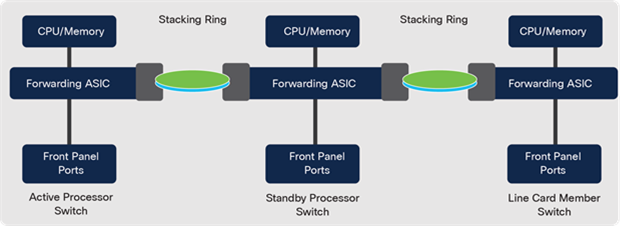
StackWise-160/80 - Two-Ring architecture
Note: Catalyst 9200 models cannot be stacked with Catalyst 9200L models.
StackWise SSO support
Catalyst 9200 Series switches support a wide range of Layer 2 stateful capabilities to provide non-stop network communication. Supported protocols are listed below:
Table 6. StackWise-160/80 stateful protocol support
| Layer |
HA-Aware protocols |
| Layer 2 |
STP, VLAN, VTP, DTP, CDP, UDLD, SPAN and RSPAN, HSRP, VRRP, 802.1x, PAgP and LACP, IGMP snooping |
| Services |
QoS, ACL, PBR, NetFlow, port security |
Power redundancy
Catalyst 9200 Series switches have two power supply bays and support hot-swappable power supplies. The power supplies operate in different modes based on the PoE and non-PoE models. PoE models support a 1+1 combined mode, where the system and PoE power is shared by both power supplies. If one of the power supplies fails, then the remaining available power from the budget is utilized. If there is not enough power in the budget, then PoE devices could be shut down, followed by the switches based on the priority.
Power priority is configurable. By default, all ports in the system are considered low priority. By default, load shedding order is as follows:
1. Low priority ports.
2. High priority ports.
3. System components.
Non-PoE models support a 1:1 redundant mode where the second power supply is completely redundant. In the event of active power supply failure, the redundant power supply becomes active immediately.
Catalyst 9300 Series High Availability
Catalyst 9300 Series switches deliver access layer redundancy with features such as StackWise, Extended Fast Software Upgrade (xFSU) and infrastructure redundancy, such as StackPower.
Catalyst 9300 Series
Catalyst 9300 Series switches with Cisco IOS XE support Cisco StackWise stacking for up to eight members. They are physically connected in a ring topology with dedicated stacking cables connected to the back of each switch.
Note: For more details about the supported mixed stacking combinations, please refer to the Catalyst 9300 StackWise System Architecture White Paper:cisco.com/go/cat9300stackwise
Catalyst 9300 Series switch stacks deliver deterministic non-blocking switching performance for up to 448 ports.
StackWise-480/1T architecture
Catalyst 9300X Series switches enable stacking using StackWise-1T, for a total stack capacity: 1 Tbps. Catalyst 9300 Series switches support stacking using StackWise-480, for a total stack capacity: 480 Gbps. Catalyst 9300L Series switches support stacking using StackWise-320, for a total stack capacity: 320 Gbps.
StackWise-480 is supported on all Catalyst 9300 non-X models (including Catalyst 9300-B models) whereas StackWise-1T is supported only on Catalyst 9300X models.
Note: When Catalyst 9300X models are stacked with Catalyst 9300 models, the stack is automatically configured with a common StackWise-480 configuration.
StackWise-480 and 1T consists of six counter-rotating rings (40 Gbps per ring on StackWise-480 or 90 Gbps per ring for StackWise-1T), and the system's throughput is a function of the aggregated throughput of these rings (240 Gbps for StackWise-480 and 540 Gbps for StackWise-1T), with spatial reuse.
StackWise-320 switches use 4 counter-rotating rings (40 Gbps per ring), and the system's throughput is a function of the aggregated throughput of these rings (160 Gbps for StackWise-320), with spatial reuse.
Note: Catalyst 9300X and 9300 models cannot be stacked with Catalyst 9300-B or 9300L models.
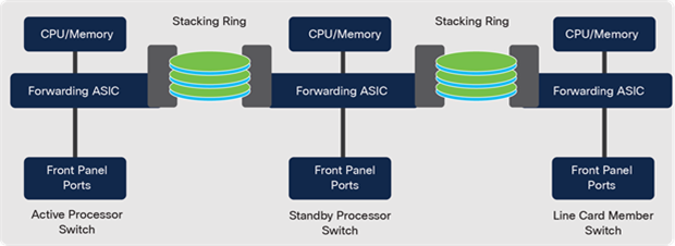
StackWise-480/1T - Six-Ring architecture
StackWise SSO/NSF support
Catalyst 9300 Series switches support a wide range of Layer 2 and Layer 3 stateful capabilities to provide non-stop network communication. Supported protocols are listed below:
Table 7. StackWise stateful protocol support
| Layer |
HA-aware protocols |
| Layer 2 |
STP, VLAN, VTP, DTP, CDP, UDLD, SPAN and RSPAN, 802.1x, PAgP and LACP, IGMP snooping, HSRP, VRRP |
| Layer 3 – IPv4 |
ARP, EIGRP, OSPF, IS-IS, BGP, MPLS LDP |
| Layer 3 – IPv6 |
ND, EIGRPv6, OSPFv3, IS-ISv3, BGPv6 |
| Services |
QoS, ACL, PBR, Flexible NetFlow, port security |
Cisco StackPower
Cisco StackPower aggregates all the available power within a switch stack into one common power pool, and shares power among stack members. Up to four switches can be configured in a power stack. Thus, if there is an 8-member data stack, then two power stacks of four switches each can be configured to utilize the complete 8-member stack. Enabling StackPower requires the use of cables connected to a special port on the back of each switch.
Note: StackWise-1T/480 must first be enabled before StackPower may be used.
Cisco StackPower reduces the number of total power supplies required per switch stack and the number of outlets required in the wiring closet. Additional savings accrue from minimizing energy wasted, due to inefficient power-supply operation at lower loads, and from the reduction in cooling within a closet. The technology also eliminates the need for external power shelves, thus freeing up additional space and power outlets.
StackPower operational modes
Cisco StackPower has two modes of operation: shared and redundant.
In the default shared mode, all input power is available for use anywhere in the stack. The total available power is used for power budgeting decisions. If a power supply fails, then the remaining available power (from the budget) is utilized and there is no impact on either the system components or PoE devices. If there is not enough power in the budget, then PoE devices could be shut down, followed by the switches based on the priority.
Power priority is configurable. By default, all ports in the system are considered low priority. By default, load shedding order is as follows:
● Low priority ports
● High priority ports
● Switch components
In redundant mode, power from the largest power supply is subtracted from the power budget. This reduces the total available power, but it allows backup power to be available in the event of power supply failure.
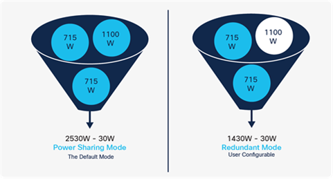
Comparing StackPower modes
Note: StackPower also reserves 30W in case a new switch is added to the stack.
Cisco StackPower allows the deployment of larger power pools when using an external Cisco eXpandable Power System (XPS 2200). Cisco XPS shares power with up to eight switches.
Extended Fast Software Upgrade (xFSU)
xFSU provides a mechanism to upgrade the software image by segregating the control plane and data plane update. It updates the control plane by leveraging the NSF architecture with a "flush and re-learn" mechanism to reduce the impact on the data plane, allowing less than 30 seconds of traffic impact during the upgrade cycle.
As an additional benefit, xFSU can also be used to manage switch reloads without performing a software upgrade with less than 30 seconds of traffic impact.
xFSU is supported on a StackWise-320/480/1T configuration and is performed in a two-phase approach. In the 1st phase: the standby and member switches are only upgraded. The 2nd stage starts with upgrading the only remaining active switch, concluding the entire upgrade process. The traffic impact during the entire process for all switches in the stack will be less than 30 seconds.
Catalyst 9400 Series High Availability
Cisco Catalyst 9400 Series switches provide several features to minimize outages:
● Dual supervisor redundancy
● Supervisor uplink redundancy
● StackWise Virtual
● In-Service Software Upgrade
● Power supply redundancy
● Power priority
Dual supervisor redundancy
Supervisor engine redundancy is enabled by default when a second supervisor is inserted into the chassis. The redundant supervisor is automatically synced with the active supervisor's running and startup configuration. SSO is triggered if the active supervisor engine fails. If NSF is configured along with SSO, then routing is not impacted during the switchover; otherwise, only Layer 2 switching is unaffected. If NSF cannot be configured on the peer device, then NSR can be configured.
Supervisor uplink redundancy
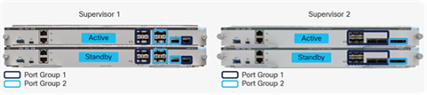
Dual supervisor uplink configurations
Catalyst 9400 Supervisor uplinks are evenly divided into 2 port groups, described above. When a Catalyst 9400 Series switch has dual supervisors installed, the switch automatically disables the second port group on both supervisors. On SUP-1/XL/XL-Y each supervisor’s active port group supports a maximum of 40 Gbps of traffic (for a total of 80 Gbps across both supervisors) and on SUP-2/XL it is 200 Gbps of traffic (for a total of 400Gbps across both supervisors).
The supervisors can support mixed interface types within the active port group. When there is a supervisor switchover, the active uplink ports on the reloading supervisor continue to forward traffic (similar to a line card) without interruption.
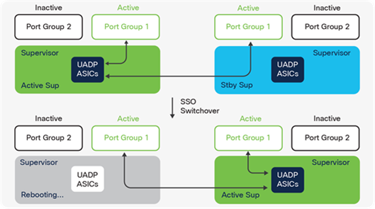
Uplinks stay active during a stateful switchover
StackWise Virtual
Catalyst 9400 Series switches support Cisco StackWise Virtual, allowing the merging of two physical switches together into a single, logical switch. StackWise Virtual also supports In-Service Software Upgrades.
Catalyst 9400 StackWise Virtual supports 252 MECs.
In-Service Software Upgrade (ISSU)
Catalyst 9400 Series switches support ISSU for both dual supervisors and StackWise Virtual. In-Service Software Upgrade (ISSU) allows customers to eliminate planned outages for full feature software upgrades. ISSU technology uses SSO and NSF as foundational features.
Note: During supervisor switchover, there will be a sub-second traffic reconvergence.
Power redundancy mode
The Catalyst 9400 Series 4-slot chassis has four power supply bays, and the 7-slot and 10-slot models have eight bays. The power supplies can operate in a combined or redundant mode.
Combined mode is the default. In this mode, all power supplies are active and share the system's load. If a power supply fails, the remaining power supplies pick up the load.
The redundant mode supports two configurations: N+1 and N+N. N+1 protects against a single power supply failure. N+N provides protection against multiple supply failures as well as a power input circuit failure.
N+1 power redundancy mode
This is a user-configured mode which allows the user to designate any one of the power supplies as a backup. The designated backup power supply remains in a standby mode. If any one of the active power supplies fail, the backup power supply is activated.
N+N power redundancy mode
This is also a user-configured mode. Here, an operator divides the power supplies into two groups: active and backup. The power supplies in the active group share the system load and the backup power supplies remain in standby mode. The two groups can be connected to the same or different input circuits. If the primary input source fails, or any one of the active power supplies fails, all backup power supplies are activated.
Power priority
Catalyst 9400 Series switches support power priority for the line cards as well as specific PoE ports to mitigate disruption to critical PoE endpoints. If the system requires more power than the available system power, due to additional PoE draw or sudden failures, the system begins shedding power. Supervisors and fan trays always have the highest priority, and this cannot be modified. By default, the switch turns off individual line cards starting with the bottom slots and then works its way to the top.
Each line card's power priority can be individually configured. If specific port priorities are configured, the load shedding decision for those ports is made by comparing the port priority value of the port and line cards. For example, ports configured with priority 0 will continue to deliver PoE while the system shuts other ports and line cards with priority > 0. If the configured priority for a line card and ports (on other line cards) match, the line card is given priority.
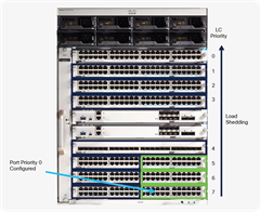
Catalyst 9400 Power Priority
Catalyst 9500 Series High Availability
Cisco Catalyst 9500 Series switches provide several features to minimize outages:
● StackWise Virtual
● ISSU with StackWise Virtual
● Power supply redundancy
StackWise Virtual
Catalyst 9500 Series switches support Cisco StackWise Virtual. StackWise Virtual allows the merging of two physical switches together into a single, logical switch. StackWise Virtual also supports In-Service Software Upgrades.
In-Service Software Upgrade (ISSU)
Catalyst 9500 Series switches support ISSU only with StackWise Virtual. In-Service Software Upgrade (ISSU) allows customers to eliminate planned outages for full feature software upgrades. ISSU technology uses SSO and NSF as foundational features.
Power redundancy mode
Catalyst 9500 Series switches support 2 power supply bays that operate in a 1+1 redundant mode, protecting against a single power supply failure. If one of the active power supplies fails, the backup power supply is activated.
Catalyst 9600 Series High Availability
Cisco Catalyst 9600 Series switches provide several features to minimize outages:
● Dual supervisor redundancy
● StackWise Virtual
● Quad-SUP RPR StackWise Virtual
● In-Service Software Upgrade
● Power supply redundancy
● Power priority
Dual supervisor redundancy
Supervisor engine redundancy is enabled by default when a second supervisor is inserted into the chassis. The redundant supervisor is automatically synced with the active supervisor's running and startup configuration. SSO is triggered if the active supervisor engine fails. If NSF is configured along with SSO, then routing is not impacted during the switchover; otherwise, only Layer 2 switching is unaffected. If NSF cannot be configured on the peer device, then NSR can be configured.
StackWise Virtual
Catalyst 9600 Series switches support Cisco StackWise Virtual (SSO between 2 members), using 1 supervisor in each chassis (known as Dual-Sup mode). StackWise Virtual allows the merging of two physical switches together into a single, logical switch. StackWise Virtual also supports In-Service Software Upgrades.
Catalyst 9600 StackWise Virtual supports 252 MECs.
StackWise Virtual with Quad-SUP RPR
Catalyst 9600 Series switches support Cisco StackWise Virtual (SSO between 2 members), using redundant supervisors in each chassis (known as Quad-SUP mode). The in-chassis standby supervisor operates in Route Processor Redundancy (RPR) mode, meaning the configuration and image are synchronized, but Cisco IOS XE processes are not online.
Quad-SUP intra-chassis redundancy is provided by the redundant supervisor, or in- chassis standby, installed into each (both) chassis. The added redundancy reduces the time taken to reach the ready state with full bandwidth and removes the hassle of human intervention to replace the failed supervisor in the event of a supervisor failure or a forced switchover.
The following supervisors make up a Quad-Supervisor StackWise Virtual:
● A StackWise Virtual active supervisor
● A StackWise Virtual standby supervisor
● In-Chassis Standby supervisors (ICS)
◦ These are the redundant supervisors which are partially booted.
◦ There can be an ICS present in one of the chassis or both the chassis.
◦ It is recommended to have 2 ICS for a fully redundant system.
For more details about Quad-SUP RPR, refer to: cisco.com/go/catalystha
In-Service Software Upgrade (ISSU)
Catalyst 9600 Series switches support ISSU for both dual supervisors and StackWise Virtual. In-Service Software Upgrade (ISSU) allows customers to eliminate planned outages for full feature software upgrades. ISSU technology uses SSO and NSF as foundational features.
ISSU with Quad-SUP RPR
1. Once the administrator starts the ISSU process, the new image is downloaded onto all 4 supervisors.
2. The ICS in each chassis is rebooted with the new image.
3. The original standby supervisor is rebooted with the new image.
4. The original active supervisor is rebooted with the new image. An SSO event is triggered and the original standby becomes the new active supervisor.
5. At this point the ISSU is complete. If at any point ISSU fails, all supervisors are reverted to the previous version and the process needs to be initiated.
Note: During supervisor switchover, there will be a sub-second traffic reconvergence.
Power redundancy mode
The Catalyst 9600 Series 6-slot chassis has four power supply bays. The power supplies can operate in a combined or redundant mode.
Combined mode is the default. In this mode, all power supplies are active and share the system's load. If a power supply fails, the remaining power supplies pick up the load.
The redundant mode supports the N+1 configuration. N+1 protects against a single power supply failure.
N+1 power redundancy mode
This is a user-configured mode that allows the user to designate any one of the power supplies as a backup.
Power priority
Catalyst 9600 Series switches support power priority for line card slots. If the system requires more power than the available system power, due to sudden failures, the system begins shedding power. Supervisors and fan trays always have the highest priority, and this cannot be modified. By default, the switch powers off the line cards starting from the bottom slots and then works its way up to the top.
Security continues to be critical with new and sophisticated attack vectors directed to enterprises and magnified by the proliferation of IoT devices and sensors with limited security capabilities. Workload and network services’ movement to multicloud and increased user movement across networks only serve to exacerbate this issue.
This chapter focuses on how the security functionality embedded in the Catalyst 9000 Family of Switches provides a comprehensive approach to securing all access across networks, applications and user types.
Excessive trust increases gaps in visibility and increases attack surface. Accordingly, organizations are moving towards a default behavior of no trust - or zero trust.
The pillars of Cisco Zero Trust include Zero Trust for the Workforce, Zero Trust for the Workloads and Zero Trust for the Workplace. In this book, we will focus on Zero Trust for the Workplace.
Cisco’s Zero Trust for the Workplace, powered by Catalyst 9000 switches, provides customers with the ability to start the zero trust journey at a point that aligns with their business priorities.
Cisco SD-Access is the only solution in the industry that provides all the capabilities required for zero trust in the workplace with visibility, segmentation, continuous trust assessment and containment that can be implemented in phases to meet each organization’s security goals.
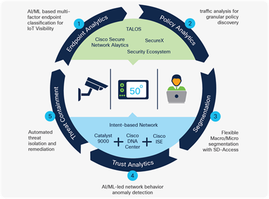
Zero Trust for Workplace components
Key capabilities within Cisco’s Zero Trust journey include:
● Endpoint visibility: Provides full knowledge of who is on the network and their network behavior (SD-Access AI Endpoint Analytics and Group-Based Policy Analytics).
● Network segmentation: Shrinks zones of trust and grants multilevel segmented access based on least privilege (SD-Access group-based access control and macro/micro-segmentation).
● Continuous Trust Monitoring: Continuously evaluates the trust of connected endpoints to help discover and contain threats rapidly (SD-Access AI Trust Analytics).
AI Endpoint Analytics
Cisco AI Endpoint Analytics gathers deeper context from the network and IT ecosystem to make all endpoints visible and searchable. It detects and reduces the number of unknown endpoints in the enterprise using the following techniques:
1. Relying on Catalyst 9000 switches to perform Deep Packet Inspection (DPI) to gather deep endpoint context by scanning and understanding applications and communication protocols of IT, OT, healthcare endpoints, etc.
2. Using Machine Learning (ML), intuitively grouping endpoints with common attributes and helping IT administrators to label them. These unique labels are then anonymously shared with other organizations as suggestions, where similar groups of unknown endpoints may be observed. This helps reduce the unknown endpoints and group them based on newer labels.
3. Integrating with Cisco and third-party products provides additional network and non-network context that is used to profile endpoints (e.g., CyberVision, ServiceNow and other third-party systems through pxGrid are supported).
Group-based Policy Analytics
Cisco’s group-based policy analytics provides the detailed information needed to define and enforce effective access policies. It gathers and analyzes actual traffic flows and presents a visual flowchart with information about service, protocol and ports used between pairs of source and destination groups.
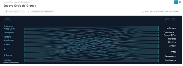
Cisco DNA Center - Group-based policy analytics
Group-based policy analytics starts where Cisco AI Endpoint Analytics leaves off. It uses endpoint groups that AI Endpoint Analytics creates, along with groups from Cisco ISE and Cisco Secure Network Analytics (formerly Stealthwatch).
Group-based policy analytics melds the view of groups with traffic flows. This provides insight into which groups are interacting with which others, supporting assessment of the best policies for the environment. By discovering existing scalable groups and their corresponding traffic, users can understand not only which groups are communicating with each other, but also the ports and protocols being used. This leads to a clear understanding of the communication needs between groups. This unique insight is crucial to policy decisions, as business needs are directly translated into meaningful policies.
Group-based access control
Once network policies are defined, they need to be transferred into the network so the infrastructure can begin to enforce them. Group-based access control presents an easy-to-use matrix with endpoint groups as sources and destinations on its axes. Each cell of the matrix represents policy, down to the service, transport protocol and port levels that govern communication between them. Such a matrix simplifies the definition of granular interaction policies between groups and makes the whole process scalable.
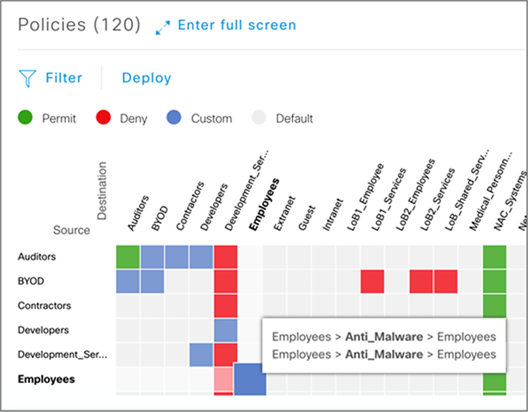
Cisco DNA Center - Group-based Access Control Policy
Group-based access control sends policies to Cisco Identity Services Engine (ISE), which functions as the security policy engine for the solution. ISE dynamically programs the network infrastructure — switches, routers, wireless access points and WLAN controllers, so these policies are enforced. All packets to and from endpoints are now appropriately tagged, placing the endpoints into the right network segment.
Macro and micro-segmentation
Overlays are virtual networks that can be thought of as multiple independent networks based on the same physical infrastructure, each of which connects just the users and resources that can communicate with each other. Cisco SD-Access creates the switching fabric necessary to build these virtual overlay networks.
The switching fabric created by SD-Access uniformly applies group-based policies irrespective of the source — wired, wireless or VPN — easing the administrative burden and enhancing user mobility. It standardizes network configuration, decreasing user configuration errors. By using verifiable policy-based segmentation that keeps traffic from different groups apart, an SD-Access switching fabric improves regulatory compliance and risk management. Placing limits on where traffic can go helps contain threats and micro-segmentation allows infected or untrusted endpoints to be quarantined.
SD-Access provides an easy way to deploy a fabric gradually over an existing traditional network. The fabric can be introduced in just the Core and Distribution layers of the switching topology. In this way, existing virtual LANs (VLANs), ACLs, etc., are preserved. Fabric access switches may enforce group-based policies using the concept of SD- Access policy-extended nodes, in which sub-tended L2 switches gain fabric benefits while still maintaining L2 access.
For more information about Cisco SD-Access, refer to the Campus Network Design chapter.
AI Trust Analytics
All devices, including OT and IoT, should be continuously assessed to check for unusual behavior, such as pretending to be trusted endpoints. Smart Building devices, such as lighting, HVAC and security cameras, need to be segmented from IT assets to prevent threats from moving laterally across the network.
Trust Analytics, using AI/ML anomaly modeling and spoofing prevention, detects traffic from endpoints that are exhibiting unusual behavior by pretending to be trusted endpoints using MAC Spoofing, Probe Spoofing or Man-in-the-Middle techniques.
When anomalies in the network are detected, Trust Analytics lowers the Trust Score for the endpoint to limit or completely deny access to the network through integration with Cisco Identity Services Engine (ISE). To generate a single comprehensive score that reflects an endpoint’s trust level, Trust Analytics takes each endpoint’s interactions within the network, evaluates its security posture, assesses its vulnerability to external attacks and checks its credentials. The Trust Score can range from low (1-3), medium (4-7) or high (8-10) depending on the probability of infection.
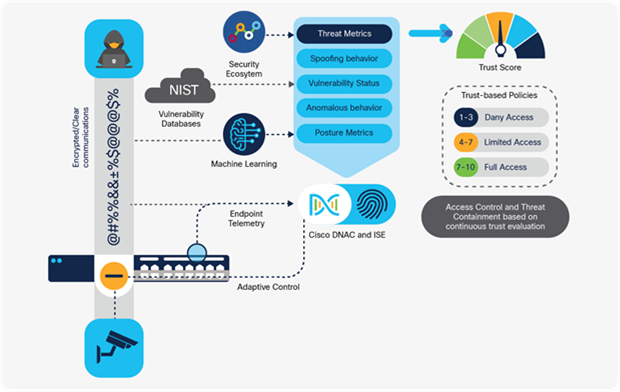
AI Trust Analytics ecosystem
To implement Zero Trust with the least privilege access, both historical and real-time traffic telemetry needs to be available to detect sudden changes in device behaviors. To accomplish this in the past, overlay solutions required copying live traffic from switches to external collectors, which run analytics on samples of traffic. These additional components and traffic load introduce deployment, configuration and maintenance complexity, thereby increasing the TCO and IT overhead.
Catalyst 9000 switches and access points, in conjunction with SD-Access, solve this problem by generating inline telemetry directly on the switches. This capability, based on the power of the Cisco programmable ASIC, eliminates the need to make copies of traffic from every switch, to external collectors, to generate the necessary security telemetry.
There are several ways the network infrastructure can be attacked. Networking equipment can either be hijacked through the installation of unauthorized software or by exploiting deficiencies in the running operating system. Even worse, a counterfeit device constructed for easy infiltration by a hacker could unknowingly be installed by an administrator. When these events occur, the network node becomes a point where an adversary can intercept private communications, exfiltrate sensitive data and launch other attacks against hosts, servers or the network itself. Cisco built the Catalyst 9000 Family of Switches to be Trustworthy, to help prevent attacks against a network.
Cisco Trust Anchor
All Catalyst 9000 switches employ a local Cisco Trust Anchor (CTA). The CTA is a specially designed, tamper-resistant chip used to power a device's built-in protections. If this chip is removed, the switch will cease to operate. The CTA incorporates a few technologies that drive on-box security.
Random number generator
Random Number Generators (RNG) are fundamental to encryption. The CTA employs a NIST-compliant (NIST SP 800-90A and B certifiable) RNG that extracts entropy from a truly random source from within the chip itself.
Secure unique device identifier
The switch has a Secure Unique Device Identifier (SUDI), an X.509v3 certificate. It is generated and installed during manufacturing and is chained to a publicly identifiable root certificate authority. The SUDI's fields contain the switch's product identifier and its serial number. Including these two fields uniquely binds the SUDI to the switch so that the device can be verified to be authentic Cisco hardware.
The CTA stores the SUDI certificate, its associated key pair and its entire certificate chain. Furthermore, each SUDI public-private key pair is cryptographically bound to a specific CTA chip. That private key is never exported.
Secure storage
A Catalyst 9000 switch CTA additionally provides a highly secure, on-chip storage area. Common items placed here include encryption keys, passwords, Locally Significant Certificates (LSC) and Local Device Identity Certificates (LDevID).
Cisco Trust Anchor technologies
By building upon the CTA core components, Catalyst 9000 switches provide hardware authentication, OS integrity and a secure boot process.
Authentic hardware check
Every network module or supervisor has its own CTA for hardware authenticity. When a module is inserted, a special library is used to read the module's local CTA and verify its authenticity. Using this makes it impossible to install counterfeit modules into a switch.
Image integrity
Providing image integrity means a user can be assured that the code they are about to run has not been modified. It is a critical step in establishing trust in a software executable. The integrity process involves creating a unique digital signature for the executable with a hashing algorithm. If the integrity check succeeds, then the code is valid and can be trusted.
Secure boot
Catalyst 9000 switches follow a secure boot process. The process begins by first establishing a root of trust which is a secure starting point. The CTA is the root of trust and is used as the basis to establish a trusted chain of valid software during the boot cycle.
Run-time defenses
With a trusted operating system loaded, protecting the firmware while it runs is the last step in setting the switch's trustworthiness. Runtime defenses for the Cisco IOS XE have been extended in many ways:
Address Space Layout Randomization (ASLR) technology has been added to randomize the locations in memory where different codes or data are located. That disables the attacking program's ability to know where to jump to inject code or steal secrets.
Why is encryption needed?
Software-based encryption capabilities are being outpaced as requirements for high- speed links increase, driven by high bandwidth applications and Wi-Fi 6/6E access points. To meet the demands of encryption required by such applications, hardware- based encryption becomes paramount to prevent harmful actors from gaining unwarranted access.
Catalyst 9000 switches support the following capabilities in hardware to encrypt Layer 2/3 packets:
● LAN MACsec
● WAN MACsec
● IPsec
LAN MACsec
An individual with an intention to harm the network could add a Tap or Layer 1/2/3 device between two directly connected network devices. The network administrator might just see a link disconnect and reconnect but might not ever find the added device. The intruder would now be able to listen to the entire data that is sent over the link and use this data for any harmful purpose. To prevent any possible intrusion through links, media access control security (MACsec) was developed. MACsec provides value by providing protection against:
● Denial of Service attacks
● Man-in-the-Middle
● Passive wiretapping
● Playback attacks
● Masquerading
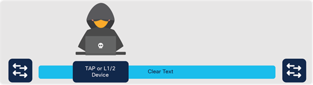
Intruder steals data on the wire
MACsec encryption
MACsec link encryption implemented in Catalyst 9000 switches is fully compliant with IEEE 802.1AE and 802.1X-2010 standards and operates at Layer 2 in the OSI stack. Layer 2 deployments were used as they involve almost every packet that is transmitted on the link without compromising network performance.
To establish a MACsec session between two directly connected Layer 2 peers, negotiation of keys needs to take place. Three session key exchange protocols can form the session: MACsec Key Agreement (MKA), Security Association Protocol (SAP) and Extended Packet Numbering (XPN).
Today, MACsec encryption is enabled between switch-to-switch, user or server host- to-switches or router-to-switches, to ensure data is protected.
Topologies
Host-to-switch — to encrypt the link between endpoints and the switch. These are typically the downlink ports on the switch.
A host is required to run the Cisco AnyConnect client to carry out software encryption/decryption on the host. Today AnyConnect supports up to AES 256-Bit encryption.
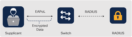
Host-to-switch MACsec encryption
Host-to-switch topology:
● Does not support manual key exchange
● Supports 802.1X key exchange (ISE is required and provides large scale)
● Supports per-user authentication/encryption
Switch-to-switch — to encrypt the links between using either uplink or downlink ports
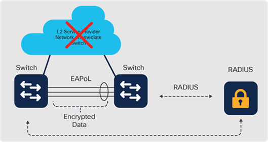
Switch-to-switch MACsec encryption
Switch-to-switch topology:
● Supports manual key exchange configuration
● Does not support 802.1X key exchange via RADIUS
● Supports EAP-TLS for MKA where dot1x supplicant is enabled on every switch and x.509 certificates are used instead of shared keys
Supported platforms
MACsec encryption requires hardware support on the switches to process encryption/decryption at a line-rate. The entire Catalyst 9000 Switching Family has specialized hardware (Silicon or MAC/PHY) which performs line-rate MACsec encryption and decryption (for 128-bit and 256-bit AES) at any speed. Both switch-to- switch and switch-to-host MACsec are supported.
The reason MACsec needs to have hardware support comes from the new packet frame format which is used to establish the MACsec session. MACsec uses a new ethertype (0x88e5) to differentiate these packets.
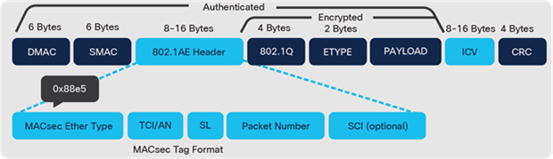
MACsec frame format
WAN MACsec
With increasing bandwidth demands over the WAN as applications move towards the cloud, a requirement for high-speed encryption without any performance impact is becoming essential.
WAN MACsec addresses such a need by providing end-to-end encryption over an L2 Ethernet WAN Service such as EoMPLS, VPLS or Q-in-Q. It may be used to secure point-to-point or point-to-multipoint WAN circuits. Use cases include secure site interconnect, DCI and storage replication.
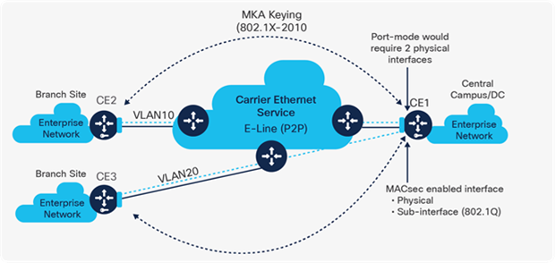
WAN MACsec encryption
Supported platforms
WAN MACsec is supported on Catalyst 9500X and 9600X platforms on all ports and speeds up to 400G simultaneously. Both 128-bit and 256-bit AES encryption are supported. Additionally, the Catalyst 9300X and Catalyst 9400X models are hardware- capable of supporting WAN MACsec.
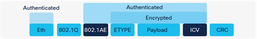
WAN MACsec frame format
IPsec
IPsec is an encryption technology delivering end-to-end protection across any Layer 3 IP network. As such, it is widely used for WAN security across the Internet for site-to- site and site-to-cloud applications.
Supported platforms
IPsec is currently supported on Catalyst 9300X models delivering secure WAN IPsec connectivity to Cloud IaaS (such as AWS, Azure, GCP), Cloud Security (such as Umbrella and zScaler) and Enterprise connections in COLOs (such as Equinix) and other enterprise campuses.
The UADP 2.0sec and UADP 3.0sec ASICs used in Catalyst 9300X and Catalyst 9400X supervisors respectively, have an embedded Crypto engine that enables unmatched 100G line-rate IPsec with very low latency and jitter, making it ideal for supporting all types of applications, including high-bandwidth or voice/video applications. The platform supports IKEv2, ESP encapsulation, Tunnel mode and AES-128/256-GCM encryption.
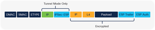
IPsec frame format
Catalyst 9000 switches support tunnel mode which is more secure than transport mode because it encrypts both the payload and the header. IPsec handles encryption at the packet level and the protocol it uses is ESP. The ESP header is added after a standard IP header. Since the packet has a standard IP header, the network can route it with standard IP devices.
Tunnel mode is often used in networks with unregistered IP addresses. The unregistered address can be tunneled from one gateway encryption device to another by hiding the unregistered addresses in the tunneled packet.
Overview
Any device that is connected to the Internet has the unintended ability to expose threats to an internal network. Network administrators must make sure that the network is safe from malicious users who are constantly scanning for loopholes and vulnerabilities to gain internal access to the network. While there are traditional firewalls that help protect the user traffic, these often rely on offline log analysis instead of real-time analysis. Cloud security provides an always-connected, constantly updated and vibrant security ecosystem delivered as a SaaS offering to customers.
Umbrella Connector
DNS is a foundational element to the functioning of the Internet. DNS attacks are so sophisticated that malformed DNS queries are hard to spot using traditional tools. DNS security provides an additional layer of security between the hosts and the internet by blocking malicious sites and filtering content. On Catalyst 9000 switches, native integration with Cisco Umbrella helps solve these challenges by acting as the first line of defense. This solution uses the DNS policy on the Umbrella Cloud to provide security at the DNS layer.
The Umbrella Connector on the Catalyst 9000 switches can be enabled in different ways:
● Cisco DNA Center
● NETCONF, RESTCONF or gNMI-based YANG API
● WebUI
● Command Line Interface
Catalyst 9000 switches with Umbrella Integration intercept the DNS queries from the end hosts and forward them to the Umbrella cloud and DNS Crypt makes sure that DNS messages are encrypted from the switch to Umbrella and vice versa. Local domains or domains destined for corporate networks can be bypassed with a DNS bypass rule on the switch.
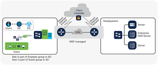
Umbrella Connector
Interface tags help to identify the interface and apply policy at the interface level. Different policies can be specified on Umbrella using this interface tag. For more granular policies, where the requirement is to apply policies per end user, Umbrella can be integrated with Active Directory. With Active Directory integration, DNS policies on Umbrella can be defined to a much more granular level up to a specific user or Active Directory group.
Secure Internet Gateways
With DNS security, only DNS queries are forwarded to Umbrella. Customers who are looking into a Secure Internet Gateway Solution (such as Secure Web Gateway, Cloud- delivered Firewall, Cloud Access Security Broker, together with DNS Security) can use the IPsec capabilities of Catalyst 9000 switches to redirect all or specific traffic from the branch to Umbrella Cloud for inspection. This helps customers with hardware consolidation at the remote branch along with providing faster time to deployment and cost reduction. With this pay-as-you-grow model, customers can provision new tunnels as they see the traffic requirements at the branch change as Catalyst 9000 switches can scale up to 100G IPsec throughput.
Tunnel provisioning
Secure tunnels can be provisioned from Catalyst 9000X switch models to any Secure Internet Gateway provider, including Cisco Umbrella or Zscaler, where secure tunnel provisioning and traffic redirection are supported.
Traffic redirection
Once tunnels are provisioned, traffic can be redirected to Secure Internet Gateways using the following approaches.
Redirect all traffic — To achieve Equal Cost Multi Path (ECMP) across multiple tunnels, multiple static routes can be created on Catalyst 9000 switches so that Internet-bound traffic is load-shared across multiple secure tunnels towards the Secure Internet Gateway.
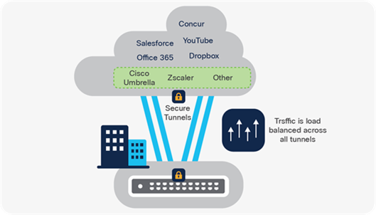
Redirect all traffic example
Redirect specific traffic — Traffic can be redirected to Secure Internet Gateways via Policy-based Routing (PBR) on a per subnet/host level granularity. With this approach, customers can pick and choose the subnets using access lists or prefix lists. They can then use route maps to map the subnets to specific tunnels (using set interface within a route map). This helps customers dynamically bring up new subnets and tunnels to provide internet connectivity without compromising security.
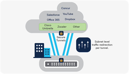
Redirect specific traffic example
Cisco DNA Center has integrated workflows to seamlessly provision multiple tunnels in a single workflow along with redirecting the traffic onto these tunnels (ECMP or PBR). Using these workflows, customers can provide these secure tunnels and redirect traffic within a single workflow.
Cisco Secure Cloud Analytics (formerly StealthWatch Cloud) Sensor
Cisco Secure Cloud Analytics is a SaaS solution for on-premises and cloud-based monitoring that gathers information about hosts by analyzing traffic patterns. This traffic is also used to model a baseline of network behavior to report anomalies. Combining this with external threat intelligence generates meaningful alerts and insights such as unwarranted data exfiltration.
There are native integrations on Catalyst 9200 and Catalyst 9300 Series switches and an inbuilt FNF collector, eliminating the need for additional probes within the network. The data is encrypted and sent to Secure Cloud Analytics for analysis. The sensor on Catalyst 9000 switches sends compressed FNF records to conserve WAN bandwidth.
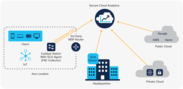
Secure Cloud Analytics Sensor
Secure Cloud Analytics on Catalyst 9000 switches can be enabled and configured with the YANG API, Web UI, traditional Command Line Interface and workflows within Cisco DNA Center to manage the integration.
Secure Cloud Analytics alerts are designed to trigger when end devices exhibit unusual behavior such as sending or receiving traffic with unusual ports or protocols.
The rapid rise of encrypted traffic is changing the threat landscape. Unfortunately, bad actors are using encryption to evade detection and hide malicious activity.
Before the introduction of the Catalyst 9000 Switching Family, detecting attacks that hide inside encrypted sessions required unwieldy and expensive measures. In short, it meant installing decryption hardware in the middle of encrypted flows. Such systems can hinder user experience by introducing unnecessary latency and the technique exposes a company to additional legal obligations and privacy issues.
Cisco solves this problem by delivering Encrypted Traffic Analytics (ETA) on Catalyst 9000 switches. ETA identifies malware communications in encrypted traffic via passive monitoring: no extra equipment is required and unnatural traffic redirection need not be performed. ETA achieves this by extracting relevant data elements and employing machine learning techniques that utilize cloud-based global security data.
ETA starts from a tried-and-true monitoring technology: Flexible NetFlow (FNF). FNF runs locally on a Catalyst 9000 switch (in hardware) and tracks every conversation or flow, that passes through it. It collects a range of information about these exchanges in a flow record. Common record values include source and destination addresses, ports and byte counts.
Cisco Cognitive Analytics
ETA integrates with Cisco Secure Network Analytics and Cisco Cognitive Threat Analytics, a cloud-based service, to apply machine learning intelligence to ETA's metadata. Cognitive processes flow data as previously described and it then compares the results to Cisco Threat Intelligence Map. The threat intelligence map feeds the cognitive analytics' engine with security data collected worldwide by Cisco Talos. The result is a more accurate assessment of a particular flow as benign or malicious.
Cryptographic compliance
ETA also identifies the encryption capabilities used by every network conversation. It reports on different cryptographic parameters in use. such as the TLS version, key exchange technique and the authentication algorithm used. This allows a security auditor to get a clear picture of which cryptographic algorithms and parameters are in use on the network to verify organizational encryption policies.
ETA on Catalyst 9000 switches
Catalyst 9000 switches are the ideal platforms for supporting ETA because they collect full Flexible NetFlow information. The collection is performed in hardware directly in the Cisco ASIC without any network performance degradation.
Not all network traffic is created equal, so there is a need to ensure Quality of Service (QoS) in the enterprise network. There are various tools and options available that can be used to better manage network traffic.
What is congestion?
Congestion is a situation where the destination port is unable to forward packets, due either to a flow from a higher speed interface to a lower one, or due to oversubscription. As a result, some packets being sent to this port are dropped or delayed. When hardware buffers are unable to absorb or buffer incoming packets, this is referred to as congestion. Adding extra buffer memory can absorb more packets, but also introduces additional latency, which can cause problems for latency-sensitive traffic.
How does QoS help?
QoS provides a set of tools to prioritize specific traffic within the same outgoing interface. During congestion, additional tools provide control over what traffic gets dropped first.
QoS in Catalyst 9000 switches
Catalyst 9000 switches perform QoS in hardware at line-rate, within the switch ASIC. Users can manage QoS with the Modular QoS CLI (MQC) model to configure traffic priorities, congestion management, policers and shapers.
Modular QoS model
Catalyst 9000 switches use the MQC model to provide the following:
● Deliver a consistent QoS configuration model based on policies, classes and actions
● Support two-level hierarchical policies
● Classify traffic by class, queue, port or VLAN
● Support class-based policing and shaping
For more information about Cisco MQC, refer to cisco. com/go/qosmqc
How QoS works
QoS on Catalyst 9000 switches occurs in three main stages, with a set of tools and functions for each stage:
● Ingress QoS Tools — Classification, Marking and Policing.
These are also used by Internal QoS for StackWise, StackWise Virtual and multi-ASICs system
● Buffers and Queuing — Congestion Management.
● Egress QoS Tools — (re)Classification, (re)Marking and Shaping.
Note: Some Catalyst 9000 switch models use a UADP 2.0 or 3.0 ASIC and others use a Silicon One Q200 ASIC. The buffer and queue architectures are different on each ASIC, but the same three main QoS stages apply to both.
QoS process on Cisco UADP
The following diagram shows the various QoS stages and processes applied to a packet as it traverses the UADP ASIC.
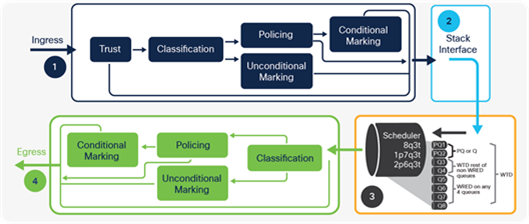
Cisco UADP ASIC QoS processing
QoS process on Cisco Silicon One
The following diagram shows the various QoS stages and processes applied to a packet as it traverses the Silicon One ASIC.
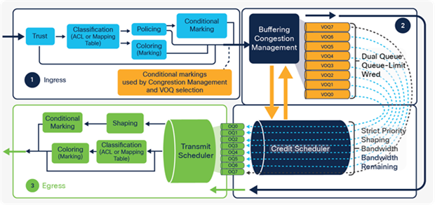
Cisco Silicon One ASIC QoS processing
This section refers to the first major stage in the QoS processing diagram above.
Ingress Classification, Marking and Policing
Trust and Classification
Ingress packet markings are trusted by default. If the default trust behavior is undesired, QoS can reclassify the packet and apply policing or re-marking.
The table below highlights the default QoS trust and queueing behavior.
Table 8. Default trust and queuing behavior
| Incoming packet |
Outgoing packet |
Trust behavior |
Queuing behavior |
| Layer 3 |
Layer 3 |
Preserve DSCP/TOS |
Based on DSCP |
| Layer 2 |
Layer 2 |
Not applicable |
Based on CoS |
| Tagged |
Tagged |
Preserve DSCP and CoS |
Based on DSCP (DSCP takes precedence) |
| Layer 3 |
Tagged |
Preserve DSCP, CoS is set to 0 |
Based on DSCP |
The Catalyst 9000 Family of Switches classifies incoming traffic based on traffic headers or other methods of matching (for example: ACLs) and can use logical constructs (i.e., AND or OR) between multiple classification parameters:
● L2/L3 ACLs
● L3 DSCP
● L3 IPP/TOS
● L2 COS
● MPLS EXP
● L4 TCP/UDP ports
● NBAR protocols
● Per-VLAN
Note: Packets not classified fall into the default-class.
QoS Marking
There are four main types of QoS priority marking based on the type of protocol:
● L2 COS, 802.1p priority — 3 bits (from 0-7)
● MPLS EXP — 3 bits (from 0-7)
● L3 TOS for IPv4 — 3 bits (from 0-7)
● L3 DSCP (IPv4), TC (IPv6) — 6 bits (0 to 63)
Policers and burst rates
Policing allows limiting specific flows to a particular data rate and allows a small number of packets to temporarily burst above the specified rate. Typically, excess traffic is dropped, but it can be configured to be forwarded with excess packets re- marked. Rate and burst are the main parameters used in a QoS policer configuration.
With a single-rate two-color policer (1R2C), the traffic rate, also known as the Committed Information Rate (CIR), is defined as the maximum number of packets that can be forwarded in a given interval. The burst is an indication of how much of a CIR can be exceeded.
While a dual-rate three-color policer (2R3C) may also include a Peak Information Rate (PIR), which is the peak rate allowed above CIR. The max burst is an indication of how much PIR can exceed.
Catalyst 9000 switches support both 1R2C and 2R3C policers.
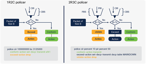
Catalyst 9000 policer types
Internal QoS
This section refers to the internal stage in QoS processing.
Cisco StackWise and StackWise Virtual
Catalyst 9000 switches running StackWise and StackWise Virtual systems follow the same rules as a standalone switch, except for the special ports used to form the Stack or StackWise Virtual Link (SVL). Stack interfaces are treated as an internal system link. You cannot apply any custom QoS or queuing policy on the SVL port.
For more information about StackWise Virtual, refer to cisco.com/go/stackwisevirtual.
Cisco UADP ASIC interconnect
The UADP ASIC interconnect is a point-to-point connection between multiple ASICs. These connections can be on the same switch or to a stack cable leading to a separate switch. An Ingress Queuing Scheduler (IQS) performs congestion management and scheduling and queuing for packets destined to other UADP ASICs. Packets with priority labels are enqueued first onto the ASIC interconnect.
Buffers and queues
This section refers to the second major stage in the QoS processing diagram.
Every packet must be placed into a piece of memory during forwarding and services processing. This process is known as buffering. Since many types and priorities of traffic must be scheduled, some packets may wait longer or be dropped during congestion.
Queuing architecture
There are two main QoS buffering and queuing architectures used in Catalyst 9000 switches, depending on the ASIC used: UADP or Silicon One Q200:
● Weighted Fair Queuing (WFQ) — WFQ fairly queues packets based on flows and priority and each flow is placed into a separate output queue. Output queues are then scheduled, based on the configured priority (weight).
◦ UADP implements an active queue management scheme based on Class- Based WFQ (CBWFQ) known as Dynamic Threshold Scaling (DTS).
◦ For more information about WFQ, refer to cisco.com/go/wfq
● Virtual Output Queuing (VoQ) — VoQ creates a logical (virtual) path to each Output Queue. A credit scheduler selects which VoQ can send traffic to egress, based on configured priority. Once at the egress Output Queue (OQs), the traffic will simply be sent out via the interface.
◦ Silicon One Q200 implements a Virtual Output Queuing (VoQ) scheme
◦ For more information about VoQ, refer to cisco.com/go/voq
Even though the QoS forwarding models between the ASICs are different, from a user experience, there is minimal difference in configuration commands.
Congestion management
If a destination port does not have the available bandwidth to transmit packets, they will begin to fill the output queues. This is known as congestion. There are three main methods of congestion management:
● [Strict] Priority Queuing (SPQ) — During transmission, high priority packets will always (strictly) take precedence over lower priority packets. This prevents low-priority packets from filling the queue.
● [Weighted] Random Early Discard (WRED) — WRED helps minimize dropping higher-priority traffic by randomly discarding some of the lower-priority traffic before it is placed into the queue.
● [Weighted] Tail Drop (WTD) — After a queue has reached its queue limit, any new incoming packets will be dropped as it enters the end (tail) of the queue, based on the priority of the class.
Queue buffers
Each queue needs to consume a certain amount of buffer (memory) space to store the transit data. The deeper the queue, the more traffic it can hold. Usage of buffers induces latency since they are holding (queuing) the packets to be transmitted.
Queue thresholds
Thresholds are configurable internal levels that define utilization points in the queue at which the congestion management algorithm can start dropping data. DSCP/COS or IP Precedence is used to assign priority to each threshold. When the threshold is exceeded, the algorithm knows which priority values are eligible to be dropped.
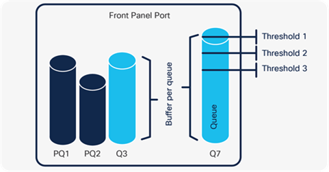
Port Queues and Thresholds
UADP buffers and queues
Cisco UADP uses a single, shared packet buffer per ASIC core. Depending on the UADP version, each core manages a subset of ports. UADP 3.0 and 3.0sec support a unified packet buffer between their two cores to increase burst absorption.
Traditionally, hardware buffers are statically allocated for each output queue. However, this can lead to insufficient buffers available for all queues in the event of bursting. To remedy this, Catalyst 9000 switches use Dynamic Threshold Scaling (DTS).
In DTS the hardware buffer is split into multiple segments:
● Ingress buffers (11%) — for packets scheduled to Stack and ASIC interfaces
● Egress stack buffers (25%) — to receive traffic from the Stack ports
The buffer is sized to accommodate up to eight Stack members.
● Egress port buffers (64%) — the largest buffers for port queue structures
These buffers can be shared between different queues and ports using DTS
UADP DTS shared pools
DTS creates a shared dynamic pool of unused buffers. Per-port buffers are split into dedicated (hard) and shared (soft) categories:
● Dedicated buffers — used for predictable performance
● Shared buffers — used for absorbing packet bursts
Dedicated buffers are allocated to each port based on speed (bps), followed by shared buffers. Dynamic Threshold Algorithm (DTA) is used to manage shared buffers:
● Shared buffers are dynamically allocated to ports during bursting or congestion
● Assignment of buffer sizes is flexible (dedicated and shared):
● Configurable dedicated threshold per port/queue
● Configurable global maximum shared threshold
● Shared pool is automatically adjusted by the DTS algorithm
UADP DTS parameters
DTS can be tuned using following parameters:
● SoftMin — minimum shared buffer space per port
● SoftMax — maximum shared buffer a port can consume from the shared pool
● Port soft start — the time when the SoftMax starts to decrease
● Port soft end — the time when the SoftMin and SoftMax are equal
For more information about DTS configuration, refer to cisco.com/go/catalystdts
UADP queue models
Users may configure hardware queuing up to eight queues with three thresholds (8Q3T) per queue. Two queues may be used for strict priority queuing. Each port can have its own egress queuing policy. The switch uses a Weighted Round-Robin (WRR) to schedule egress traffic from its transmit queues.
UADP congestion management
The UADP 2.0-based and UADP 3.0-based platforms add the Weighted Random Early Discard (WRED) algorithm to the queuing process.
Note: The priority queues do not use WRED.
Silicon One Q200 buffers and queues
The Silicon One Q200 ASIC uses two sets of buffers, to minimize latency, provide extra capacity to reduce congestion and absorb bursting:
● Shared Memory Subsystem (SMS) — 80 MB of specialized shallow buffers for low latency queueing of packets
● High Bandwidth Memory (HBM) — 8 GB of on-demand buffers to address microbursts and deep packet queueing
All packets are initially placed into the SMS buffer memory and scheduled, based on priority. Higher-priority packets in SMS experience minimal latency. If congestion occurs or a burst of packets arrives, lower-priority packets may be moved to the HBM buffer. All Q200 ASIC slices have equal access to both SMS and HBM buffer.
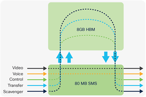
Cisco Silicon One SMS and HBM buffers
Silicon One Q200 queue models
The Silicon One Q200 ASIC uses a Virtual Output Queue (VoQ) forwarding model. Every interface in the system, physical or logical, will have a VoQ assigned. The independent nature of VoQs prevents congestion in any queue from affecting other queues.
By default, Catalyst 9000 switches with Silicon One Q200 can implement eight (0-7) queues for every interface, for classifying traffic with up to 7 priority queues with decreasing priority.
Note: L3 sub-interfaces use a two queue (high and low) model, per sub-interface.
Silicon One Q200 congestion management
In addition to support for up to 7 priority queues, the Silicon One Q200 platforms perform the WRED algorithm as part of the (ingress) VoQ queuing process, using the concept of discard-class. Silicon One Q200 supports two WRED values (discard-class 0 or 1) which are used to conditionally or unconditionally “color” the packets Green (high priority) or Yellow (low priority). Yellow packets will be dropped by WRED to avoid congestion.
Note: Priority queues do not use WRED.
Catalyst 9000 buffer scale
The table below describes the buffer size per core and ASIC.
Table 9. Buffer scale information
|
|
UADP 2.0 Mini |
UADP 2.0/2.0sec |
UADP 2.0 XL |
UADP 3.0/3.0sec |
S1 Q200 |
| Buffers per ASIC |
6 MB |
16 MB |
32 MB |
36 MB |
80 MB SMS 8 GB HBM |
This section refers to the final stage in the QoS processing diagram.
Egress classification, marking and shaping
The ingress classification and marking will be carried to the egress processing. Traffic can be further reclassified or remarked before it is transmitted.
Packets will normally be transmitted up to the maximum available bandwidth, but an administrator can specify how much bandwidth can be used by different traffic classes. This is known as shaping. A shaper typically 'delays' excess traffic, using a buffer or queue mechanism to hold packets and 'shape' the flow, allowing packets time to dequeue.
UADP Egress queueing and scheduling
Catalyst 9000 switches with UADP ASICs use an Egress Queue Scheduler (EQS). Each port supports up to eight egress queues, two of which can be configured as priority queues. Weighted Round Robin (WRR) techniques are employed to empty the transmit queue in proportion to the assigned weights.
Silicon One Q200 Egress queueing and scheduling
Catalyst 9000 switches with Silicon One Q200 ASICs leverage the VoQ credit scheduler along with the Port Transmit Scheduler. Each VOQ has a shaper that can be attached to it. The VOQs will be mapped to the actual output queues on the egress port and the packet will be put into them. Each port supports up to eight egress queues, seven of which can be configured as priority queues.
Shapers
Shaping is the process of imposing a maximum rate of traffic while regulating the traffic rate in such a way that downstream devices are not subjected to congestion. Shapers are applied on the hardware queues on Catalyst 9000 switches.
The shaping feature is enabled on a particular traffic class. Normally, class-based shaping is used to impose a maximum rate for a physical interface or logical interface as a whole. The following shaping forms are supported in a class:
● Average rate shaping
● Hierarchical shaping
Average Rate shaping
The queue bandwidth is restricted to a configured value, even though the port may have more bandwidth available. Shaping can be done either with a percent, ratio or target bits per second.
Hierarchical shaping
Shaping can also be configured at multiple levels in a hierarchy. This is accomplished by creating a parent policy with shaping configured and then attaching one or more child policies with additional shaping configurations to the parent policy.
Hierarchical QoS (HQoS) allows two policy levels to be configured for QoS, allowing greater policy granularity. Hierarchical policies consist of a parent policy at the top level and a child at the bottom level. Both UADP and Silicon One support Hierarchical QoS operations in hardware.
HQoS operations
Port shaper
An HQoS port shaper applies a shaper to all egress traffic by default using class-default. Within this shaped bandwidth, additional child policies can be specified.
● Only the class-default class can be used in the parent policy
● Up to 7 priority queues are allowed in the child policy in Silicon One Q200 switches
● Up to 2 priority levels for UADP-based Catalyst 9000 switches
● Different bandwidth per non-priority class in the child policy is permitted
● On Silicon One-based switches using HQoS with sub-interfaces, this allows for WRR bandwidth sharing between sub-interfaces.
This is the only supported operation on Silicon One-based Catalyst Switches. UADP-based Catalyst 9000 switches support 3 additional HQoS operations:
Aggregate policer
An HQoS port shaper applies a policer to all egress traffic by default using class-default. Within this policed bandwidth, additional child policies can be specified.
● Only the class-default class can be used in the parent policy
● Only one or two priority queues are allowed in the child policy
● Different bandwidth per non-priority class in the child policy is permitted
Per-port, per-VLAN policy
Multiple HQoS parent policers are applied with each policer matching a VLAN as its classifier. Within each VLAN's individual policer bandwidth, additional child policies may be applied.
● A table-map can be used as a set action in the child policy
● Multiple classes under a parent policy are permitted
● Shaping can be used instead of per-VLAN classification
Parent using shaper
Multiple HQoS shapers are applied under the parent policy, with each shaper matching a traffic class. Within each individually-shaped bandwidth, additional child policies may be applied.
● Table-map can be used as a set action in the child policy
Modern switching networks use virtual network overlays to support mobility, segmentation, encryption and programmability at scale.
GRE, IPsec and VXLAN QoS
GRE, IPsec and VXLAN are overlay technologies that encapsulate the original IP packet and frame with an outer IP packet header without modifying the original payload.
Overlay Encapsulation
In GRE encapsulation, the original IP packet is encapsulated with the new IP and GRE header and the ToS byte value from the inner IP header is copied to the outer IP header. GRE interfaces do not support QoS policies on ingress.
IPsec encryption is similar to GRE, the original IP packet is encapsulated with new IP and IPsec header and the ToS byte value from the inner IP header is copied to the outer IP header.
In VXLAN encapsulation, the original L2 frame is encapsulated with new IP and VXLAN header and the ToS byte value from the inner IP header, which is part of the original L2 frame, is copied to the outer IP header.
The egress queuing is based on the original (copied) header values.
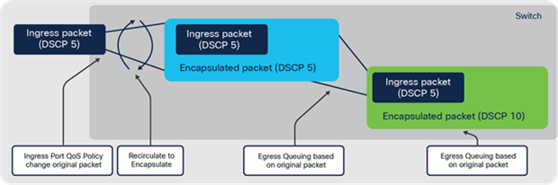
QoS marking for GRE/VXLAN overlay encapsulation
Note: The queueing actions are applied before egress policing/marking actions.
Overlay Decapsulation
In all three cases, when a QoS policy is applied on the ingress interface (where packets arrive encapsulated), only the outer header is used for classification and QoS only affects the outer header. The inner packet will not be changed and retains the original marking.
Note: The GRE/IPsec/VXLAN tunnel interfaces do not support egress QoS Policies.
When a QoS policy is applied on the egress interface (where the original decapsulated packet exits), the policy will affect the original packet.
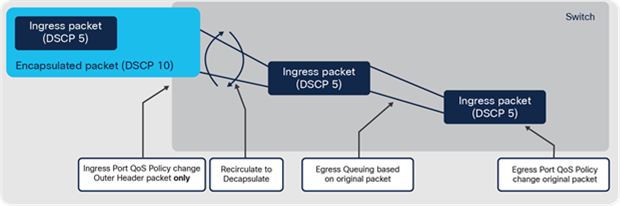
QoS marking for GRE/IPsec/VXLAN overlay decapsulation
For more information about QoS on GRE overlays, refer to cisco.com/go/qosmqc
● (RFC 2784 tools.ietf.org/html/rfc2784)
For more information about QoS on VXLAN overlays, refer to cisco.com/go/qosmqc
● (RFC 7348 tools.ietf.org/html/rfc7348)
MPLS QoS
MPLS overlays use the MPLS experimental bits (EXP) field in the MPLS header for QoS marking. The EXP bits can be used to carry some of the information encoded in the IP DSCP and can also be used to encode the dropping precedence.
By default, IOS XE copies the three most significant bits of the DSCP or ToS field of the IP packet to the EXP field in the MPLS header. However, the EXP field can be set by defining a mapping between the DSCP or ToS and the EXP bits.
There are two modes used to map DSCP or ToS to EXP within Catalyst 9000 switches:
● Uniform mode (default) — has only one layer of QoS, end-to-end
The ingress PE router copies the DSCP from the incoming IP packet into the MPLS EXP bits of the imposed labels. As the EXP bits travel through the core, the bits may or may not be modified by intermediate P routers. In case of modification, the new EXP value is copied back to DSCP bits of the IP Packet.
● Pipe mode — uses two layers of QoS
◦ Underlying QoS for the data, which remains unchanged when traversing the ASIC
◦ Per-hop QoS, which is applied to the outer header, separate from the underlying IP packet
When an IP packet reaches the edge of the MPLS network, the egress PE router classifies the newly exposed IP packets for outbound queuing based on the EXP bits from the removed MPLS label. The inner IP packet DSCP bits are not modified.
Below is a brief description of the various MPLS QoS modes:
Table 10. MPLS QoS modes
| Tunneling mode |
IP to label |
Label to label |
Label to IP |
| Uniform |
ToS/DSCP copied to MPLS EXP (may be changed by SP) |
MPLS EXP may be changed by SP QoS policy |
MPLS EXP copied to IP ToS/DSCP |
| Pipe |
MPLS EXP set by SP QoS policy |
Original ToS/DSCP preserved (egress based on MPLS EXP) |
|
| Short- pipe Not supported |
Original ToS/DSCP preserved (egress based on ToS/DSCP) |
For more information about MPLS QoS, refer to cisco.com/go/mplsqos
IT Staff are asked to enforce end-to-end business policies, achieve target performance and quickly isolate and resolve application performance problems. In addition, network engineers need detailed insight into the different types of applications on the network to optimize business-relevant traffic performance.
This section focuses on the collection of traffic flow analytics data and flow data storage, export and other related data sharing functions.
NetFlow is a Cisco IOS XE technology that provides statistics on packets flowing through a network device. A traffic "flow" is generally defined as a unique session between source and destination devices, often represented as a TCP/IP 5-tuple with source IP, destination IP, source port, destination port and protocol.
Flexible NetFlow (FNF) adds the capability to customize the traffic collection parameters for specific requirements. Many analytics solutions use FNF, including Application Visibility and Control (AVC), Network as a Sensor, Encrypted Traffic Analytics (ETA) and Performance Monitoring.
FNF collects statistics about incoming or outgoing flows on Catalyst 9000 interfaces and then stores the data of each flow in a cache. This flow data can then be viewed locally or exported to an external collector.
FNF has the following four basic functions:
● Flow Record(s) — matching and collection of packet fields
● Flow Exporter(s) — specifies a destination FNF server
● Flow Monitor(s) — binds flow records and exporters and enables FNF
● Interface(s) — flow monitors are applied to ports, input or output
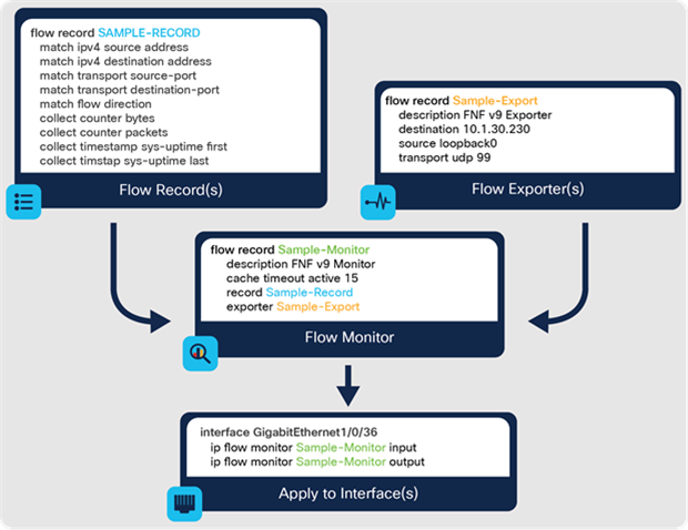
Cisco Flexible NetFlow components
For more information about Cisco Flexible NetFlow, refer to cisco.com/go/fnf
Note: The FNF architecture differs based on the Switch ASIC, but the same four FNF functions apply.
UADP Flexible NetFlow
FNF on Catalyst 9000 switches with UADP ASICs are performed entirely in hardware. There is a dedicated ASIC memory table where flow records are stored. The maximum scale depends on the size of this memory table and the number of ASICs. FNF configuration and export functions are performed in IOS XE software.
For more information about FNF on Catalyst 9000 with UADP, refer to cisco.com/go/uadpfnf
Silicon One Q200 Flexible NetFlow
FNF on Catalyst 9000 switches with Silicon One Q200 ASIC uses a hardware-assisted software sampling process. The ASIC samples unique flows to software, using a dedicated CPU to build flow records. The maximum scale depends on the sample rate. FNF configuration and export functions are performed in IOS XE software.
For more information about FNF on Catalyst 9000 with Silicon One, refer to cisco.com/go/q200fnf
Application Visibility and Control (AVC)
Catalyst 9000 switches support the Application Visibility and Control (AVC) solution by leveraging FNF and Network-Based Application Recognition 2 (NBAR2). The Cisco AVC solution leverages multiple technologies to recognize, analyze and control more than 1400 applications, including voice and video, email, file sharing, gaming, peer-to-peer and cloud-based applications.
Cisco AVC has three main functions:
● Application recognition for traffic based on Layer 4 and above flow data
● Ability to identify traffic as business-relevant versus business irrelevant
● Control by prioritizing application bandwidth, such as business-relevant traffic
AVC can be enabled on interfaces for both standalone and stacked switches. AVC is enabled by adding the match application name command to an FNF record and applied on switch ports. The AVC solution is compatible with NetFlow v9 and IPFIX.
The application identity (from NBAR2) can also be used as a match condition in a QoS policy for application-based traffic priority.
NBAR2
Network-Based Application Recognition 2 (NBAR2) provides Deep Packet Inspection (DPI) capabilities based on L4 and L5 data, enhancing the application recognition engine to support over 1400 applications (including 140+ encrypted applications).
NBAR2 provides powerful capabilities, including:
● Categorizing applications, such as category, sub-category and application group
● Field extraction of data such as HTTP URL, SIP domain, mail server, etc.
● Customized definition of applications based on ports, payload values, etc.
● Customizable attributes for each protocol (such as business-relevant or irrelevant)
Catalyst 9000 switches use a performance-optimized software-assisted AVC (NBAR2) method in which only a few packets are needed to identify the application, reducing the impact on the switch CPU. After recognition, the application ID is installed into the FNF table for subsequent processing.
Note: In a Catalyst 9300 Series switch stack, FNF runs on each stack member, scaling the overall solution as more members are added, but AVC runs on the active member.
For more information about AVC on Catalyst 9000, refer to cisco.com/go/catalystavc
Software-Defined AVC (SD-AVC)
SD-AVC, also known as Controller-Based Application Recognition (CBAR), using Cisco DNA Center. SD-AVC is an extension of AVC and NBAR2, providing additional application definitions (currently more than 3000) by connecting to external sources of information such as Infoblox and Microsoft Office 365.
SD-AVC then provides these additional application definitions to the AVC (NBAR2) process running on the Catalyst 9000 switches controlled by Cisco DNA Center.
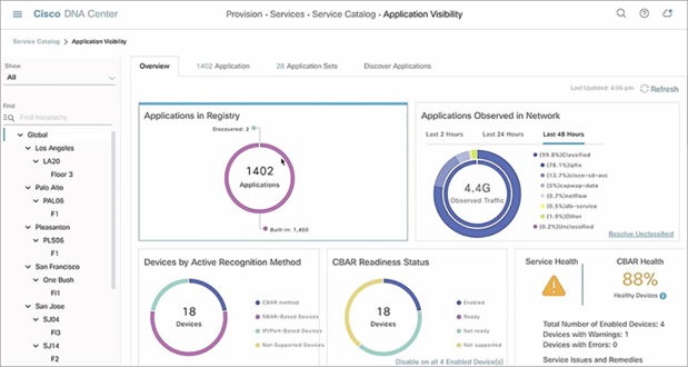
Cisco DNA Center — Software-Defined Application Visibility
For more information about Cisco SD-AVC, refer to cisco.com/go/SDAVC
ThousandEyes combines various active and passive monitoring techniques to give deep insight into user experience across the applications and services the network provides and consumes. The solution leverages comprehensive Internet monitoring data to provide real-time internet outage detection, powered by collective intelligence.
ThousandEyes monitors network infrastructure, troubleshoots application delivery and maps internet performance, all from a SaaS-based platform. ThousandEyes provides below benefits and more.
Network visibility
● End-to-end network path and metrics across any network
● Identify issues down to the service provider, location and interfaces
App experience
● Quickly isolate issues to application, network or other services
● Understand the performance of user interactions with applications
Correlated insights
● Correlate network and app issues with internet routing, internal network devices and global outage events
ThousandEyes solution is comprised of three main components:
● Enterprise Agents — correlate external service delivery paths with internal LAN and device metrics and alert or report on the availability of services.
● Cloud Agents — monitor hybrid and multicloud connectivity and performance of third-party APIs from the cloud Virtual Private Clouds.
● Endpoint Agents — real-time end-user monitoring of domains through browser-based plug-ins deployed on end-user laptops and desktops.
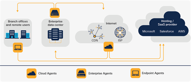
Cisco ThousandEyes Solution: Visibility from everywhere that matters
ThousandEyes with Catalyst 9000
Catalyst 9000 switches can be integrated with ThousandEyes using the application hosting framework. ThousandEyes Enterprise Agents can be deployed directly on Catalyst 9000 switches to provide additional benefits:
● ThousandEyes Docker container can natively run on the flash
● ThousandEyes units are included with the Cisco DNA Advantage license
● Access to ThousandEyes management dashboard
ThousandEyes Enterprise agent on Catalyst 9000 offers the best-in-class service assurance for applications and networks, providing end-to-end visibility with historical performance data.
Note: To run additional tests, including Browser bot tests, an external SSD is required.
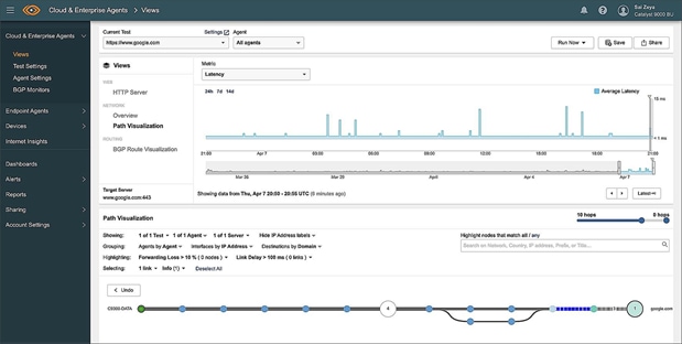
Cisco ThousandEyes dashboard view
For more information about ThousandEyes on Catalyst 9000, refer to cisco.com/go/te
Networks with time-sensitive applications have been deployed with technologies such as GPS to provide a timing source, but these networks are complex to deploy, scale and manage. Precision Time Protocol (PTP) provides nanosecond time accuracy and allows customers to migrate from dedicated and isolated networks to unified Campus networks. These converged deployments enable faster deployment times, reduced cost and more scalable network operations.
Catalyst 9000 switches support PTP across Access, Distribution and Core layers, enabling the convergence of these time-sensitive applications and devices with existing Ethernet infrastructure. Catalyst 9000 switches support PTP version 2 (PTPv2) with IEEE 1588v2 enabled by default. PTP on the Catalyst 9000 switches operates in 2-step mode. PTP version 1 (PTPv1) packets are transparently forwarded by Catalyst 9000 switches and do not participate in the PTPv1 domain.
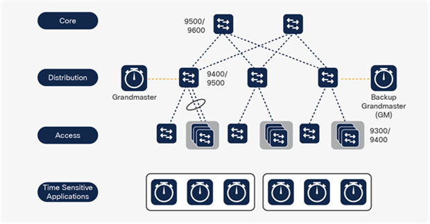
Time-sensitive Networks and applications
The diagram illustrates a PTP-enabled converged Ethernet network. Endpoints running time-sensitive applications are connected at the access layer and PTP is enabled on all transit switches across the data paths of the applications.
A PTP domain is made up of PTP-enabled devices. These devices can be endpoints or network devices that process or transit PTP packets to achieve time synchronization across the network.
Catalyst 9000 switch ports can operate as a Grandmaster (GM), Boundary Clock (BC), Transparent Clock (TC) or Ordinary Clock (OC) in a PTP network.
PTP was originally defined in IEEE 1588. PTP is used across different network types, such as: industrial, power, telecom and Audio/Video (A/V or AV) networks. Each of these networks have different requirements for time synchronization and IEEE 1588 has defined different profiles for all these network types. For example, AES67 profiles are aimed toward audio networks, whereas G8275.1 serves telecom networks.
The Catalyst 9000 Family of Switches supports the following PTP profiles:
1588v2 Default (PTPv2): Enabled automatically when PTP is configured. Network transport in 1588v2 mode can either be L2 (default) or users can optionally change the transport mode to L3.
802.1AS (generic PTP, gPTP): Designed for Audio Video Bridging (AVB) networks. This profile is mainly enabled in L2 multicast-only networks. The unicast feature must be configured for networks that span across multiple buildings requiring gPTP or gPTP over L3. More information about gPTP can be found at: cisco.com/go/gptp
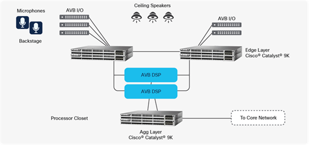
AVB Network
AES67 (Audio Engineering Society 67): Standard defines for high-performance audio- over-Ethernet interoperability in a multi-audio vendor environment. AES67 supports both L2 and L3 transport modes.
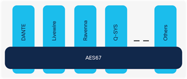
ASE67 interoperability across multiple vendors
G8275.1 (Telecom Profile): Defined in ITU-T, G8271.1 provides full timing support and is used in mobile cellular networks that require synchronization of time and phase.
Catalyst 9000 switching platforms with G8275.1 profile support only T-BC and T-TC. This profile is used in 4G (fourth generation) and 5G (fifth generation) cellular telecommunications technology.
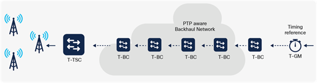
ITU-T G.8275 telecom profile - PTP timing support from the network
For more information about Precision Time Protocol, please refer to: cisco.com/go/ptp
In the past, Audio and Video deployments have traditionally relied on analog, point-to- point infrastructures for implementation and deployment. With the migration of AV to digital transmission, these infrastructures have retained their point-to-point nature. This deployment model has resulted in very cumbersome and expensive deployments with significant operational challenges.
Proposed solutions to these digital implementation issues have often been non- standard, expensive and came with a significant operational burden. Standard Ethernet was widely viewed as a new way forward for Audio and Video deployment (one that could offer a common medium and do so flexibly and inexpensively). Ethernet, however, was not designed for the low-latency, predictable, lossless requirements of digital AV networks.
These challenges led to the development of the Audio Video Bridging (AVB) set of standards. These consist of the following major areas:
● IEEE 802.1BA — Umbrella standard of protocols and profiles for features, options, configurations, defaults, protocols and procedures for AVB devices.
● IEEE 802.1Qat — Stream Reservation Protocol (SRP) and Multiple Stream Reservation Protocol (MSRP) provide an end-to-end admission control system required for AV streams, ensuring availability of resources and low latency.
● IEEE 802.1Qav — Forwarding and queuing For Time-Sensitive Streams (FQTSS), provides an AV traffic scheduling mechanism.
● IEEE 802.1AS — Generic Precision Time Protocol (gPTP) provides time synchronization for time-sensitive applications on L2 devices.
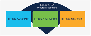
IEEE802.1BA as the umbrella AVB standard
AVB is an important part of the future of digital media production and the Catalyst 9000 switches offer full support for this important set of standards.
AVB standard is currently supported on Catalyst 9300 and 9500 switches (10G and 40G only models). With an AVB-capable endpoint and switch, analog AV signals are aggregated at AVB endpoints and transmitted on the Catalyst-based infrastructure. As a system, AVB is a cost-effective and flexible solution to collapse AV infrastructures onto reliable, simple Ethernet media.
For more information about AVB, please refer to www.cisco.com/go/avb
The AVNU Alliance is a consortium of professional, automotive, consumer electronics and industrial manufacturing companies working together to establish and certify the interoperability of open Audio Video Bridging (AVB) and Time-Sensitive Networking (TSN) standards. Catalyst 9300 and 9500 switches have gone through rigorous testing in a multi-vendor environment and are AVNU-certified for Audio and Video Bridging (AVB) Deployments. Specific models supported can be found on the AVNU Product page at avnu.org/certified-product-registry/
Smart and Sustainable Buildings
Water, gas and electricity are the three traditional utilities. Smart Buildings add a fourth-technology.
Using a variety of technologies to collect, aggregate and analyze user data in real-time, Smart Buildings provide insights and analytics that enable IT staff to rapidly adapt to their users. The result is better resource management and more sustainable outcomes, physically and financially.
A smart and sustainable network can also enable IT staff to create user-centric experiences and promote a trusted workplace environment that:
● Protects personal health
● Offers personalized facility resources
● Offers more opportunities for collaboration
● Enhances personal efficiencies
● Reduces and reports power consumption
● Keeps users and their data secure
For more information about Cisco Smart Buildings, please visit cisco.com/go/smartbuildings
Smart buildings start from a central network connected to the Internet of Things (IoT). Think of IoT as the edge of the network. Often located in remote or hard-to-reach areas, IoT devices can be sensors that collect and transmit data securely back to the central network.
IoT continues to be one of the fastest-growing industry trends and it is driving important innovations in existing technologies such as Power over Ethernet (PoE), as well as new technologies and solutions such as Cisco Spaces, Cisco DNA Service for Bonjour and Application Hosting.
For more information about Cisco Internet of Things, please visit cisco.com/go/iot
Organizations worldwide are reimagining workspaces to attract and retain talent and achieve business goals, such as net-zero. Cisco Smart Building solutions allow the creation of intuitive, trusted facilities that help enhance health, safety and energy efficiencies as a foundation for the future of work.
Environmental (green) initiatives
Smart workplaces and space utilization
Smart buildings add significant business value by providing flexible workplaces that deliver better experiences, emphasize collaboration and optimize a building’s usage rates.
Smart buildings deliver:
● Attractive, flexible and welcoming workspaces that foster productivity
● The latest technology, while securely supporting wired and wireless connectivity
● Optimized usage (per square foot) by understanding and influencing usage patterns
● Optimized space configuration based on user needs and behaviors
● Real-time workspace and network usage reporting and analytics
● Self-optimization (automation) is based on user needs and preferences, availability of resources, energy costs, weather and other variables.
Savings and sustainability
Smart buildings empower quantitative monitoring of workspace and system utilization to lower resource usage and costs, increase revenue and align with the expectations of corporate programs and applicable regulatory and certification bodies (such as the U.S. Green Building Council LEED rating system).
Smart buildings aim to achieve:
● Reduced up-front construction costs and time for cabling and installation
● Lowered CapEx, labor and materials costs related to construction, maintenance and life cycle
● Usage of the building’s network as a sensor for data-driven equipment optimization and quantification of energy consumption (reducing carbon footprints).
● Enablement of pervasive 90W UPOE+ throughout a building, on multiple types of switches
● Centralized and automated environmental controls (using AI/ML, software applications and a single-pane-of-glass management system).
● Improved environmental conditions and air quality that enhances health, safety and quality of life
● Eligibility for a variety of local, state and federal tax incentives and program credits
Cisco Smart Buildings framework
Leveraging years of experience in foundational technology, combined with state-of- the-art security and location-based services, Cisco Smart Buildings solutions create a blueprint for taking control of a building. As a comprehensive set of technologies, Cisco Smart Buildings start with security and focus on flexibility and are managed with advanced machine learning that enables visibility, control and automation.
Cisco Smart Buildings solutions function as an interface between different wired and wireless IoT solutions. They also open a wealth of new sources of data, allowing buildings to adapt to changing conditions, empower a trusted workplace today and prepare for the ever-evolving future.
For a Cisco Smart Buildings guide, please visit cisco.com/go/smartbuildingguide
The Smart Buildings solution combines the following technologies:
● Cisco Catalyst 9000 Family of Switches and Access Points
● AI Endpoint and Trust Analytics
The following sections detail each of the technologies.
The Catalyst 9000 Switch Family
The Catalyst 9000 Switch Family provides physical wired and wireless infrastructure including PoE innovations for smart buildings. The PoE innovations are detailed in the following sections.
Power over Ethernet (PoE) innovations
Power over Ethernet (PoE) is ubiquitous in campus deployments today. PoE is a foundational technology in many modern networks, connecting devices such as IP phones, wireless access points, IP-based cameras, LED lights and other IoT endpoints. A single Ethernet connection provides both data and power to the endpoint simultaneously. PoE removes the need for electrical cabling and wall sockets to power each device and eliminates the cost of additional electrical cabling and circuits.
From the original Cisco Inline Power (ILP) implementation, which was limited to 7 watts (7W) of maximum power, PoE has now been standardized as IEEE 802.3af (commonly known as PoE, providing up to 15.4W) and IEEE 802.3at (known as PoE+, providing up to 30W). The increased PoE power, as well as standardization of PoE, has fueled the proliferation of a large and thriving ecosystem of PoE-powered devices.
Cisco has pioneered PoE since its inception, driving new advances to the standard and setting the stage for the next phase of PoE innovation. As device requirements pushed beyond the 30W maximum power defined by 802.3at, Cisco led the way with the definition of Cisco UPOE (Universal PoE). UPOE provides for up to 60W of PoE power. In 2018, IEEE 802.3bt was ratified and approved introducing two additional types of power: 60W (Type3) and 90W (Type4). Cisco UPOE is 802.3bt (Type 3) compliant. Cisco UPOE+ also adds support for 802.3 bt (Type 4).
Both Catalyst 9300 Series switches and Catalyst 9400 Series line cards support 802.3bt (up to 90W) power options on 1G and mGig copper ports, accommodating both higher throughput and greater PoE power. These switches enable highly dense PoE deployments scaling up to 384 ports of 90W from a single system (8-member Catalyst 9300 stack or a 10-slot Catalyst 9400 chassis). With configurable PoE port and line card priorities, IT/OT staff can make sure that their critical IoT endpoints do not get impacted during a partial power failure event. Cisco's innovation of StackPower in the Catalyst 9300 Series allows for sharing of PoE power across multiple stackable switches. This provides significant benefits in High Availability and ease of deployment.
Catalyst 9200 Series switches support both PoE and PoE+. Depending on the number and capacity of power supplies used, the different levels of power may be available on all or a subset of the ports.
Fast PoE, Perpetual PoE and 2-Event classification
As PoE has proliferated, so have its use cases. One of the newer innovative uses of PoE is to power building lighting systems. For example, using UPOE/UPOE+ ports as the single power source for daisy-chained commercial and industrial lighting.
Additional uses include directly powering IoT devices in building systems, such as building controls, thermostats, HVAC control systems, door locks, badge readers and other critical building infrastructure.
To support these business-critical (and always-on) deployments, Cisco created two new capabilities for PoE, known as Fast PoE and Perpetual PoE.
● Fast PoE — provides PoE power almost immediately during the switch bootup process. Rather than waiting for the entire IOS XE control plane to load, Fast PoE aims to provide PoE power in less than 30 seconds after power is applied to the switch. It is important to bring IoT and similar devices online as quickly as possible, after a power outage, rather than waiting several minutes for a full reload.
● Perpetual PoE — has a similar but different goal. Perpetual PoE keeps PoE power available even during an IOS XE control plane reload. This ensures continuity of power to attached devices. If the switch is reloaded (such as during a software upgrade), it is undesirable to power down critical PoE devices during the reload cycle.
The Catalyst 9000 Family of Switches supports 2-event classification. With this, devices can negotiate power faster without using L2 protocols (CDP/LLDP) by using L1 negotiation. This allows endpoints to negotiate power in under a second, leading to faster onboarding of devices.
For more information about PoE and UPOE, please refer to: cisco.com/go/poe
Cisco DNA Center
Cisco DNA Center is a powerful network controller and management dashboard that helps teams to design, manage and troubleshoot the network. It also provides network automation and assurance, with AI/ML including PoE assurance and analytics for Smart Buildings.
Power Assurance and Analytics
Cisco Power Assurance and Analytics delivered through Cisco DNA Center assists IT/OT teams to plan, deploy and monitor devices and proactively troubleshoot and optimize energy consumption across the enterprise. This helps complement the goal of energy savings and environmental sustainability.
Cisco DNA Center allows easy viewing and assessment of real-time analytical data from connected PoE devices. The Power Assurance Dashboard includes the dashlets for PoE device operational state, powered device distribution, port availability, power allocation and various PoE insights. Integration with troubleshooting workflows provides a single management plane for all power-related operations.

Cisco DNA Center — Power Assurance
Each of these dashlets also has a trend option, allowing the user to go back in time and get a Power usage snapshot at the complete network level, site level or a per-device level.
In addition to PoE insights and usage, the Power section in the Device 360 Assurance provides details on the real-time power usage of the switch and the total/remaining power budget that is available to PoE endpoints.
Endpoint and Trust Analytics
Cisco DNA Center AI (Artificial Intelligence) Endpoint Analytics is a next-generation endpoint visibility feature, equipped with AI-driven analytics and Deep Packet Inspection (DPI).
Users can also create custom profiles based on the attributes that Endpoint Analytics learns about a specific endpoint. The Cisco Smart Building framework leverages Endpoint Analytics to profile IoT endpoints automatically as they are onboarded onto the network.
Trust Analytics further monitors the endpoint behavior and assigns a trust score on a scale of 1 to 10, based on the behavior seen from an endpoint. Users can quarantine the endpoint based on the trust score.
Cisco Identity Service Engine
Cisco ISE provides highly secure network authentication and policy to users and devices. ISE integrated with Cisco DNA Center can leverage AI Endpoint Analytics data for policy creation. Cisco DNA Center relays endpoint profiling information to ISE. This information can be used on ISE for customer policy creation (e.g., dynamic downloadable ACL push to a switch when detecting a specific endpoint).
For more information about Cisco AI Endpoint Analytics, refer to: cisco.com/go/endpointai
Cisco Spaces
Cisco Spaces is a SaaS-based cloud platform that provides location-based analytics for people (visitors, guests, employees) and things (assets, sensors, smart devices). Cisco Catalyst switches can host the IoT gateway using the Application Hosting Framework. The IoT Gateway lifecycle is managed via the Cisco Spaces Dashboard.
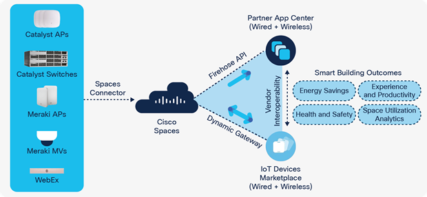
Cisco Spaces ecosystem
This solution uses the ERSPAN feature on Catalyst 9000 switches to relay data from endpoints to the IoT Gateway that is hosted on the switch. The IoT Gateway relays sensor data and telemetry to the Cisco Spaces dashboard. Cisco Spaces has a wide variety of partner applications to deliver the desired outcomes based on specific use cases. The application store is a third-party application integration system that the customer can use.
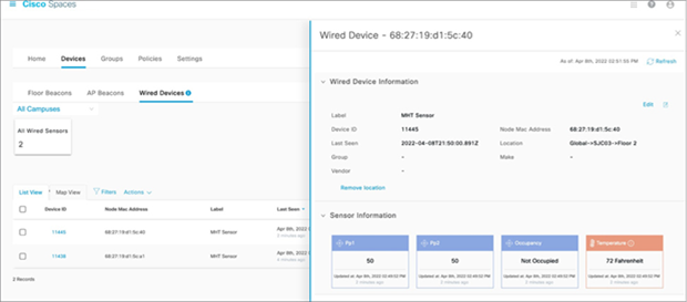
Telemetry from a wired sensor as seen on Cisco Spaces Dashboard
Note: Cisco DNA Advantage license for switching software includes Cisco Spaces Extend license.
For more information about Cisco Spaces, please refer to: cisco.com/go/spaces
Ecosystem Partners
Cisco has partnered with a large number of Ecosystem partners to drive Smart Sustainable Building adoption. A list of all EcoSystem partners can be found here: cisco.com/go/smartbuildingpartners
The Bonjour protocol is optimized for plug and play use in home and small office deployments. The mDNS protocol, implemented by Bonjour, is widely used in campus environments such as education and retail for device discovery and simplified connectivity to network services. Based on the multicast DNS (mDNS) standard, it is used with many devices and service types, including many Apple, Google and Amazon devices, to provide easy discovery of devices and simplified device attachment.
The mDNS protocol uses link-layer (L2) multicast for device and services discovery and is inherently not routable, limited to the local L2 broadcast domain (i.e., one-hop only). This limits the deployability and use of the Bonjour protocol in larger enterprise networks, which use routed infrastructures.
To address this challenge, Cisco introduced the Cisco DNA Service for Bonjour with capabilities of Service Discovery Gateway (SDG) and Service peering on enterprise switching and wireless platforms to provide uniform policies across wired and wireless networks. This solution also eliminates flooding of mDNS packets and converts all queries upstream from the client into unicast, thus providing a more stable environment even on a Layer 2 network through the service peering capability.
The goal of the SDG feature is to allow reachability to Bonjour services, even when a Bonjour client and the offered service are in different L3 IP subnets, on the same network device.
To extend this, Cisco DNA Service for Bonjour scales to an enterprise network-wide application that runs on Cisco DNA Center and provides policy-based access to Bonjour services across the entire network.
For example, a public school may desire for the teachers to have the ability to connect to an Apple TV device to display classroom content, while also ensuring that the students attached to the same network do not have this capability.
Note: Policy-based filtering of mDNS advertisements are not supported by the native Bonjour protocol.
By combining SDG, Service Peer and Cisco DNA Service for Bonjour (on Cisco DNA Center), IT staff can enable scalable Bonjour services across their entire enterprise environment, with a powerful set of policy-based access controls.
For more information about Bonjour and mDNS, please visit cisco.com/go/bonjour.
Applications are used in enterprise networks for various business-relevant use cases. Examples of enterprise applications include performance monitoring tools such as ThousandEyes, IoT applications such as CyberVision and security tools such as Intrusion Detection Services. Traditionally, such applications would operate on an external physical or virtual server.
Application hosting on the Catalyst 9000 Switch Family opens innovative opportunities by converging network connectivity with a distributed application runtime environment. For instance, applications such as ThousandEyes are enabling increased network monitoring and visibility use cases, as discussed within the 8 - Network Visibility chapter.
For maximum flexibility, the Cisco application-hosting framework (IoX) on the Catalyst 9000 switches uses Docker containers for hosting applications. The framework enables customers and partners to build their own applications or bring their applications onto the network devices while maintaining security and isolating resources of IOS XE.
For more information about Cisco IoX on Catalyst 9000 switches, refer to cisco.com/go/iox.
Cisco IOS XE 16.12.1 introduces the Application Gigabit Ethernet (AppGigE) interface, as well as Docker container support on the Catalyst 9000 switches. The AppGigE interface is an internal data link that is hardware-switched between the front-panel ports to provide connectivity to the Docker container. Platforms without the AppGigE interface can bridge a front panel port to the Management port for container connectivity.
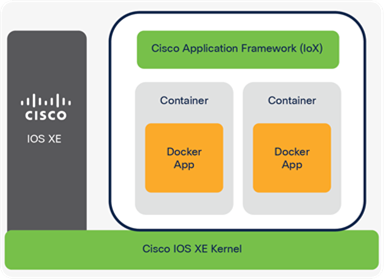
Cisco Application Hosting Framework (IoX)
Cisco IOS XE running on Catalyst 9000 switches reserves dedicated memory and CPU resources for application hosting. By reserving memory and CPU resources, the switch provides a separate execution space for user applications. It protects the switch's Cisco IOS XE runtime processes, ensuring their integrity and performance.
Applications must reside in one of the external Solid-State Drive (SSD) storage options using either USB 3.0 or M2 SATA and can also be secured with a password to meet high-security use cases.
Note: Certain Cisco signed applications can run on the internal flash.
Table 11. Catalyst 9000 Application Hosting resources
| Platform |
Memory (GB) |
CPU cores |
External Storage (GB) |
AppGigEthernet Port |
| Catalyst 9200 |
N/A |
N/A |
N/A |
N/A |
| Catalyst 9300 |
2 |
1 x 1.8 GHz |
240 |
1 x 1G |
| Catalyst 9300X |
8 |
2 x 2.4 GHz |
240 |
2 x 10G |
| Catalyst 9400 |
8 |
1 x 2.4 GHz |
480/960 |
1 x 1G |
| Catalyst 9400X |
8 |
1 x 2.3 GHz |
480/960 |
2 x 10G |
| Catalyst 9500 |
N/A |
N/A |
N/A |
N/A |
| Catalyst 9500 High Performance |
8 |
1 x 2.4 GHz |
480/960 |
1 x 1G RJ45 (Mgmt0) |
| Catalyst 9500X |
8 |
1 x 2.3 GHz |
480/960 |
2 x 10G |
| Catalyst 9600 |
8 |
1 x 2.0 GHz |
480/960 |
1 x 10G SFP+ (Mgmt0) |
| Catalyst 9600X |
8 |
1 x 2.7 GHz |
480/960 |
2 x 10G SFP+ (Mgmt0,1) |
In addition to the dedicated hardware resources listed above, Catalyst 9000X models include x86 CPU Quick Assist Technology (QAT), which can significantly increase encrypted application performance by offloading symmetric/asymmetric encryption and authentication, digital signatures and lossless data compression.
Cisco Signed applications
Cisco signed applications include the Guest Shell, ThousandEyes Enterprise Agent and Cisco DNA Space IoT gateway, discussed in more detail in the 8 - Network Visibility section. Benefits include running applications on internal flash without impacting the performance of the switching features.
Hosting multiple applications
Cisco recommends running only one application on a single switch. Starting from the IOS XE 17.5.1, support was added for hosting multiple applications on a single switch, for applications that are signed by Cisco. Application resource requirements must be met, and SSD storage is required to run multiple applications.
Application Lifecycle Management
Cisco DNA Center provides a centralized, enterprise-wide, user interface and APIs to deploy and manage the entire lifecycle of the applications. Catalyst 9000 switches can also be managed through the Command Line Interface (CLI), from YANG (through NETCONF, RESTCONF, gNMI) and the IOS XE WebUI (GUI).
Application Hosting High Availability
The Application auto-restart feature provides cold restartability of an application and the underlying app-hosting framework. It retains the last configured operational state of an application in the event of system switchover or restart and is enabled by default.
Stack switches need to be in 1+1 redundancy mode and use the same application storage medium on both Active and Standby switches. The platforms listed below are supported applications with High Availability.
Table 12. Application Hosting High Availability support
| Platform |
IOS XE Release |
| Catalyst 9300 StackWise (1+1 mode only) |
17.2.1 |
| Catalyst 9400 Dual Sup (Single Chassis and StackWise Virtual) |
17.5.1 |
| Catalyst 9500 High-Performance StackWise Virtual |
17.5.1 |
| Catalyst 9600 Dual Sup (Single Chassis and StackWise Virtual) |
17.5.1 |
For more information about Application Hosting on Catalyst 9000 switches, refer to cisco.com/go/apphosting.
The following factors influence decisions from a configuration and operational point:
● Network infrastructure is growing rapidly in terms of number of devices and applications
● There is a need for rapid innovation and greater flexibility
● There is a requirement to reduce OpEx and increase productivity
● There can be a lack of confidence that changes will be successful, usually due to insufficient testing
● There are too many manual processes
All these factors lead to a growing need for automation at every level, from device provisioning to fully automated configuration, management, monitoring and troubleshooting of network devices and infrastructure.
Network device programmability is the set of features provided by the network operating system that enables automation, management and visibility.
Options for Network Management — your network, your way
Cisco IOS XE provides many network management options providing the flexibility needed to handle a broad range of deployments and network sizes, large and small. This enables network operators to utilize the management option that best fits their needs.
Catalyst 9000 switches can be managed with Cisco’s advanced on-premises and cloud- managed controller solutions as well as traditional mechanisms including the Web User Interface (WebUI), the Command Line Interface (CLI) and 3rd-party do-it-yourself integrations that leverage the various device APIs.
Cisco Controller solutions
Cisco DNA Center is a powerful on-premises network controller and management dashboard that helps you to design, manage, monitor and troubleshoot the network. It offers guided workflows specific to the job role in NetOps, AIOps, SecOps or DevOps. Cisco DNA Center provides capabilities and workflows for functions that can broadly be categorized into the following:
● Design — Intuitive workflows for designing the network, starting with locations where your network devices will be deployed.
● Policy — User and device profiles for secure access and network segmentation, as well as application policies to prioritize business critical traffic.
● Provision — Policy-based automation to deliver services to the network, zero- touch device provisioning and software image management.
● Assurance — Visibility into application performance and user connectivity in real-time with path-trace visibility and guided remediation.
● Platform — Open and extensible platform allowing third-party applications and processes to collect network intelligence from Cisco DNA Center for workflow and process automation.
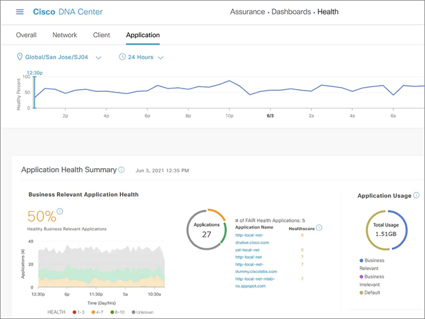
Cisco DNA Center Assurance dashboard
Additional information is available in the Cisco DNA CentereBook as well as from Cisco DevNet: https://developer.cisco.com/dnacenter/
Cisco Meraki Dashboard is a SaaS offered cloud-managed network controller and management dashboard. Devices are centrally and securely managed from the cloud using a single web-based dashboard. This cloud-managed intuitive architecture enables customers to save time, reduce operating costs and solve business problems quickly and efficiently. Meraki Dashboard supports cloud management for a select set of Catalyst 9300 Series switches. Cloud monitoring of Catalyst 9000 switches is also available.
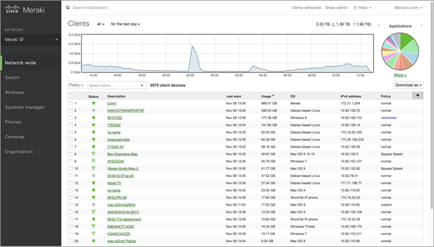
Cisco Meraki Dashboard
For additional information, see: https://meraki.cisco.com/lib/pdf/meraki_datasheet_cloud_management.pdf
Cisco’s Network Services Orchestrator (NSO) is another powerful controller solution that abstracts network intent and maintains configuration state. Details are available from https://developer.cisco.com/site/nso/
Other Network Management Tools
The Web User Interface (WebUI) is a Graphical User Interface (GUI) device-management tool that provides the ability to configure and monitor a device. It is embedded in the system image with every license. To enable WebUI on a device, the HTTPS server and local or external server authentication needs to be configured.
The Command Line Interface (CLI) is the most common way that network engineers interface with the switch directly and the available commands are well documented in configuration guides and command references.
Model-Driven Telemetry (MDT) — SNMP has long been used for telemetry collection, however, it is being superseded by MDT interfaces. MDT provides a more detailed, secure and scalable method to ensure visibility and provide alerting systems with the needed data.
Do-it-yourself (DIY) customers and partners can directly access network devices to build their own custom solutions to automate every phase of the device lifecycle. For more information about device programmability, refer to http://cisco.com/go/iosxeebook
Cisco IOS XE provides several options for an automatic, accurate, consistent and repeatable provisioning process at a lower operating cost. It also enables shorter deployment times than a traditional manual process using one of the following mechanisms:
● Cisco network Plug and Play (PnP)
● Zero-Touch Provisioning (ZTP)
● Preboot eXecution Environment (PXE)
Cisco Network Plug and Play
Cisco Network Plug and Play (PnP) is a secure device provisioning solution integrated with the Cisco DNA Center controller enabled via DHCP or DNS. PnP provides a simple, secure, unified and integrated solution for enterprise network customers to ease new branch or Campus rollouts. Configuration, image upgrades and patch management are managed through the Cisco DNA Center GUI or API and the entire process can be fully automated.
Cisco DNA Center provides Day 0 automated workflows to onboard Catalyst 9000- enabled non SD-WAN branches. These workflows use PnP for provisioning of switches and auto-establishing IPsec tunnel connectivity to the corporate network.
Zero-touch Provisioning
Zero-Touch Provisioning (ZTP) enables standards-based provisioning of devices via DHCP, TFTP/HTTP and Python scripts by leveraging the Guest Shell Linux container and is enabled with DHCP option 67. The device learns about the configuration from the DHCP option and downloads the Python script from the TFTP or HTTP server to configure the device either via CLI or YANG. The provisioning logic implemented in the downloaded Python script is flexible and allows partial or full configuration of devices in one or several phases, including image upgrade.
Detailed examples and implementation details for ZTP are available from Cisco DevNet’s Code Exchange platform at: cisco.com/go/iosxeztp
Preboot eXecution Environment
Preboot eXecution Environment (PXE) is yet another standards-based provisioning process used by system administrators to provision servers based on standard protocols such as BOOTP, DHCP and TFTP. When the IOS XE device boots up, instead of using the pre-loaded image, it sends a DHCP request to look for a PXE server. The PXE server then sends an image to the device which it uses to boot up.
Cisco IOS XE provides PXE based on iPXE, which is an Open Source version of PXE created to support additional protocols such as HTTP. The PXE process is frequently described as Network Boot.
Day 1 — Application Programming Interface (API)
Cisco has introduced many different APIs over the years, from the very first IETF NETCONF implementation in 2006 to cutting edge gRPC microservices that are actively being defined by industry partners.
The diagram below illustrates the API stack with a common YANG data model infrastructure, built on top of device-level features, to define both device configuration and operational state. Different protocols such as NETCONF, RESTCONF and gNMI can be used to interface with external automation software toolchains.
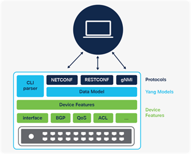
Device Application Programming Interface stack
Data models
Data models are one of the most important components of programmable APIs. They define the data structure, syntax and semantics of a given feature and are meant to solve the issue of unstructured data provided by CLIs.
YANG Data Models
Yet Another Next-Generation (YANG) is the RFC7950 data modeling language developed by the IETF to enable the reuse of data models across equipment from different network vendors. It is widely used by network operators to automate the configuration and monitoring of network devices and defines the capabilities of the API.
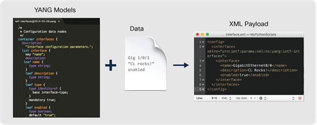
YANG models example
As shown above, YANG data models can be considered templates. YANG models need actual data to build operations that can be exchanged with a network device and to retrieve or change the device configuration or operational state.
● Configuration data models — the set of writable data required to transform a system from its initial default state into its current state. A configuration model instructs the device to do something and can be mapped to the running configuration of a Cisco IOS XE device.
● Operational data models — the set of read-only data status information and statistics on a device. An operational data model consists of what the device is actually doing and is mapped to the information traditionally provided by show commands.
● Execution data models — the set of execution data models is used to trigger actions on the device and does not necessarily represent config or operational data. These models can be used to enable programmatic actions such as to release a DHCP lease, trigger a reload, save configurations, copy files or trigger the software image upgrade process.
Both configuration and operational data models can be further classified as Cisco Native or open data models.
● Cisco Native — is specific to the network operating system capabilities. There are Cisco native models for each one of the features supported, including interfaces, crypto, EVPN, etc.
● Open data models — are defined by standards bodies such as IEEE and IETF or by working groups such as OpenConfig. An advantage of using open models is that they are common across Operating Systems and vendors and provide a consistent way to manage devices.
Cisco publishes YANG data models in a common GitHub Repository at https://github.com/YangModels/yang/tree/master/vendor/cisco which is updated with the data models for each release. The YANG data models can also be downloaded directly from the device over any of the programmatic interfaces.
YANG Suite and YANG Tooling
Many tools have been created to navigate through data models, device API interfaces, perform validation and to build various API operations.
● Cisco YANG Suite (developer.cisco.com/yangsuite/) provides the testing and validation environment for all IOS XE device API features and capabilities. From building and sending API payloads with NETCONF, RESTCONF and gNMI, to receiving Model-Driven telemetry with NETCONF, gNMI and gRPC, this tool is widely used for a variety of validation, testing and integration use cases.
● PYANG (github.com/mbj4668/pyang) — Python library and CLI tooling to validate, navigate and automatically build documentation from YANG.
● YANG Catalog (yangcatalog.org/) — an online reference for YANG modules that is updated with each Cisco Network Operating system release.
Device API Protocols
The various interface protocols supported by Cisco IOS XE on Catalyst 9000 switches share a common YANG data model infrastructure. Regardless of the API interface, the same set of data models are used.
The diagram below shows the main differences between the various API protocols at each layer of the stack, starting with the Transport (SSH vs HTTP vs HTTP2), the different encoding formats used for the Remote Procedure Calls (RPCs), as well as different sets of operations.
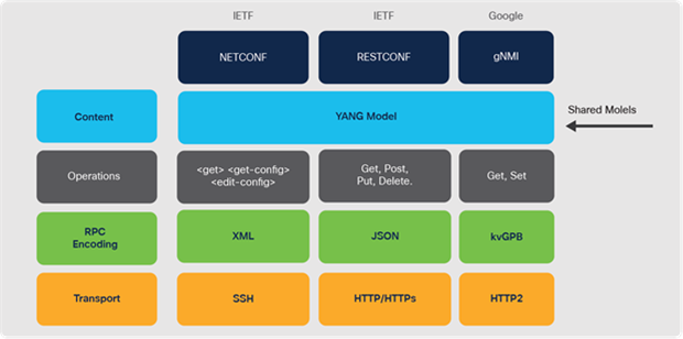
Comparison of device API protocols
NETCONF
NETCONF is the network configuration protocol defined by the IETF in RFC6241 to help network operators manage their networks. The NETCONF protocol stack includes SSH transport, messages in the form of YANG-modeled RPCs and encoded using XML
The main NETCONF operations are:
●
●
●
RESTCONF
RESTCONF is a network configuration protocol defined by the IETF in RFC8040. It is a network configuration protocol for accessing YANG models built using the principles of the commonly known and understood HTTP REST framework. The RESTCONF stack includes HTTP/HTTPS transport, messages in the form of YANG modeled RPCs and encoded using either XML or JSON as set within the HTTP headers.
The RESTCONF operations are the standard REST verbs:
● GET — to retrieve a resource
● POST — to create a new resource
● PUT — to create or modify a resource
● PATCH — to update a new or existing resource
● DELETE — to delete a resource. Similar to an
● HEAD — to retrieve header metadata
gNMI
gNMI is the gRPC Network Management Interface developed by Google. gNMI provides the mechanism to install, manipulate and delete configuration of network devices and also to view operational data. The content provided through gNMI can be modeled using YANG and encoded using JSON_IETF in accordance with the RFC7951
gNMI operations are:
● CAP — sent to the network device on first connect to discover device capabilities
● GET — to retrieve the device configuration or state. Includes attributes such as Prefix, Paths and Data Type
● SET — to change the device configuration including support for SetUpdate and SetReplace
The gRPC Network Operations Interface (gNOI) is an additional part of gNMI that leverages Google Protocol Buffers to implement workflow APIs for certificate management, operating system upgrades and factory reset services.
Day 2 — Model-Driven Telemetry
Network monitoring challenges
Automation solutions based on CLI and SNMP have over time proven to be incomplete, inefficient and hard to scale and maintain. New requirements in terms of speed, scale, fault isolation, forensic analysis and near real-time data availability, are making legacy monitoring solutions insufficient for most organizations.
Dial-In and Dial-Out Model-Driven Telemetry
There are several MDT interfaces available that provide different transport and encoding options in a similar way to APIs.
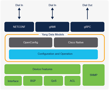
Model-Driven Telemetry stack
The main consideration when selecting the MDT interface is where the telemetry connection is initiated from. Dial-Out is the configured telemetry subscription where the details are configured like any other device feature from the CLI or API. Dial-In is the dynamic telemetry subscription where the tooling collector first establishes the session and then defines the telemetry configuration.
Table 13. Telemetry comparison of Dial-In and Dial-Out
| Dial-In (dynamic) |
Dial-Out (static or configured) |
| Interface: NETCONF, gNMI |
Interface: gRPC |
| Telemetry updates are sent to the initiator subscriber |
Telemetry updates are sent to the specified receiver/collector |
| The life of the subscription is tied to the connection (session) that created it and over which telemetry updates are sent. No change in the running configuration is observed. |
A subscription is created as part of the running configuration; it remains the device configuration until the configuration is removed |
| Dial-in subscriptions need to be re- initiated after a reload because of established connections or sessions being killed during stateful switchover |
Dial-out subscriptions are created as part of device configuration and they automatically reconnect to the receiver after a stateful switchover, network or tooling outage |
| Subscription ID is dynamically generated upon successful establishment of a subscription |
Subscription ID is fixed and configured on the device as part of the configuration |
Telemetry notifications
Telemetry notifications occur either on a pre-defined time scheduler or when an event occurs. The Periodic update interval uses a predefined interval usually between 5 seconds and 5 minutes, but depends on the use case and business requirements. Examples of periodic notifications are CPU and memory utilization and interface packet counters. The On-Change update interval only sends information when there is a change or as the event occurs, for example failed logins, interface state change and other faults and alarms.
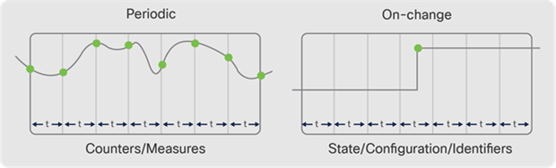
234AGRAM Periodic vs. On-Change subscriptions
Collection of Model-Driven Telemetry
For testing and validation, the Cisco YANG Suite tooling can be used to Dial-In to NETCONF and gNMI and to function as the receiver for the gRPC Dial-Out telemetry. Once the telemetry has been validated, there are several solutions available to process, store and visualize the data for production use cases. The most common tooling stack is “TIG” or Telegraf, InfluxDB and Grafana. Telegraf is the collector and receiver of telemetry data directly from IOS XE. Telegraf will send any received telemetry to the InfluxDB where it is stored and later used by other tools for visualizing the data and alerting of it. The Grafana Dashboarding tool can be used to access the data within the InfluxDB to display data over time and with more meaningful representations.
For more information about Model-Driven Telemetry, refer to the repository on Cisco DevNet’s Code Exchange platform: cisco.com/go/iosxemdt
Day N — Scripting and Integration
Guest Shell
The CentOS 8 Linux container that is embedded within IOS XE is called the Guest Shell. It provides an isolated user environment where scripts and tools can be leveraged while integrating with Python, Embedded Event Manager (EEM) and NETCONF.
Python Scripting
Scripts have been used for ages to quickly and easily automate small tasks, and Python has become one of the most popular scripting languages. One of the main reasons for Python’s ever-growing popularity is how easy it is to get started. It provides an interactive shell, allowing a quick way to execute scripts line by line and is more human-readable than most other scripting languages. It also has an extensive package management system called pip that makes installing additional libraries and tools easy.
Python scripts can be used to automate a Catalyst 9000 switch running Cisco IOS XE in two different ways, off-box and on-box scripting.
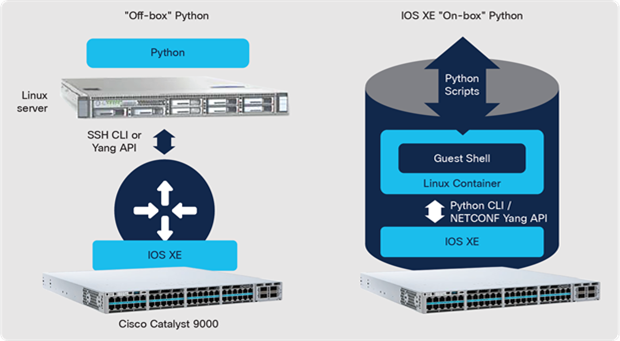
Cisco IOS XE off-box and on-box Python
● Off-box Python — the script is executed from an external server and it connects to the Cisco IOS XE device using IP connection with SSH for CLI-based automation or with the YANG API including NETCONF, RESTCONF or gNMI.
● On-box Python — the Python script is executed inside the Catalyst 9000 switch in a built-in Linux container named Guest Shell. From the Guest Shell environment, Python scripts can access the underlying Cisco IOS XE using the same mechanism used by off-box Python scripting.
Cisco Embedded Event Manager (EEM) provides additional capabilities to administer switches by tracking and monitoring events that take place and then applying actions that were previously configured. EEM can be used to run scripts or jobs at a predetermined schedule, such as every 5 minutes or once a day around midnight. There is tight integration between EEM and the Python API and it can also be used to programmatically act on Syslog messages that occur or when there are logins and other manual interactions on the device.
Configuration management tools consistently automate systems and applications at scale. Such tools have been used by system administrators for more than a decade. Configuration management tools have a variety of advantages:
● A consistent approach across different vendors and operating systems
● Easy integration with version control systems
● A simple way to collect hardware and software device data
● Provides an intent-based configuration approach
● No changes are made if the system, application or device is already in the desired state
Infrastructure as Code (IaC): Adopting Infrastructure as Code allows infrastructure and operations teams to leverage the same agile practices that application developers use.
IaC can be implemented using tools such as Terraform and Ansible.
● Terraform is a popular cloud-native and agentless tool that leverages the RESTCONF API interface to define the intended infrastructure-as-code state. Terraform is used to orchestrate and configure a variety of cloud services, applications and network devices.
● Ansible is an agentless management tool that can be used to configure any device features using SSH CLI and it also has support for NETCONF, RESTCONF and gNMI-modeled configurations. Ansible is heavily used to configure a variety of applications, services and network topologies including BGP-EVPN.
Cisco pyATS has been used extensively within and outside of Cisco for many years because it has such wide support for a variety of Cisco Network Operating Systems as well as parsers and support for other networking vendors. pyATS supports both SSH/Telnet + CLI as well as programmatic interfaces.
CI/CD is continuous integration and continuous deployment, a practice used to reduce the time needed to deploy new changes into production and to reduce the risk associated with the changes. It enables this through an automated testing process and integration with source control systems including a rollback in case failures occur. Customers implementing CI/CD frameworks have experienced lower development cycles, a faster pace of innovation and lower total IT cost.
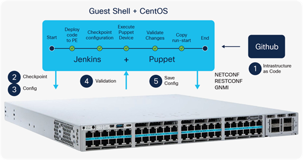
Cisco Catalyst 9000 switches CI/CD with Github/Gitlab/Jenkins
Cisco’s Developer Network: DevNet
Cisco DevNet at developer.cisco.com/ provides free developer resources that support customers and partners who leverage APIs and integrations supported across Cisco products. DevNet provides learning labs, video courses and device sandboxes to help clients learn and use the developer ecosystem in simulated and physical switches, along with API documentation, community resources and more.
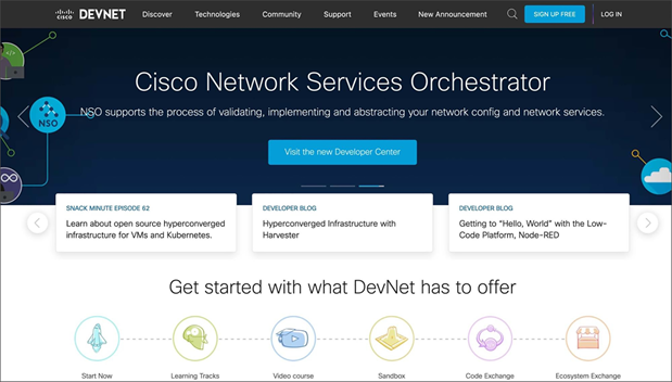
Cisco DevNet
Packaging, Licensing and Support
The Catalyst 9000 Switching Family uses a simplified licensing model with the same software packaging and licensing across all platforms. This licensing model provides the following benefits:
● Simplifies the packaging of features
● Delivers a more cost-effective way of consuming features
● Lowers up-front costs by adding more features and support
● The term-based licensing for Catalyst 9000 Switches includes the following options:
● Cisco DNA Essentials: Provides the baseline network functionality used to operate a network and includes the perpetual Network Essentials functionality.
● Cisco DNA Advantage: Includes all the functionality in the Cisco DNA Essentials package (including Network Essentials) plus advanced capabilities such as advanced security, availability, automation and assurance and the perpetual Network Advantage functionality.
Each software license option is offered with a 3, 5 or 7-year term and includes solution support, the Cisco Enhanced Limited Lifetime Hardware Warranty (E-LLW) and Cisco Smart Net Total Care Service support for the life of the term. While the renewal of the term license is not mandatory, if the term license is allowed to expire, switch functionality will revert to the perpetual base network functionality and solution support will end.
For more information, see:
www.cisco.com/go/dnasoftwarematriix
www.cisco.com/go/dnasoftwarebook
Optional add-on Expansion Pack
The Expansion Pack provides easy purchase of add-on Cisco licenses, appliances and services along with a Cisco DNA Essentials or Advantage license using one convenient ordering menu.
Available for:
● Cisco Identity Services Engine (ISE)
● Cisco Secure Network Analytics
● Cisco Spaces
● Cisco ThousandEyes
The Cisco Feature Navigator tool is available from cisco.com/go/cfn and provides a complete list of all features for each package. Not all functionality is available across all platforms.
Licenses can be purchased in two ways: Transactional and Enterprise Agreement (EA).
Transactional: Both perpetual and subscription licenses can be purchased in ad-hoc transactions. Each subscription transaction maintains its own term length.
Enterprise Agreement (EA): The Cisco Enterprise Agreement gives access to world- class solutions across the entire Cisco enterprise software portfolio, under a single contract that can scale rapidly as your business changes. The Cisco EA brings together industry-leading Cisco DNA software, Meraki and Cloud Networking offerings with other Cisco capabilities to accelerate an organization’s implementation of critical cross- technology solutions more effectively, while allowing the flexibility to adjust and adapt networking infrastructure dynamically. Purchasing through the Cisco Enterprise Agreement provides customers economies of scale and license management simplicity while providing financial predictability, access to incentives and subscription co-termination.
Cisco Meraki: Includes all the features and functionality of current Meraki MS switches including full cloud management with Meraki Dashboard.
The Meraki cloud device license is a set duration with an expiration date and varies by port count and feature set — Essentials or Advantage. Each device license is offered with a 1, 3, 5, 7 or 10-year term and includes solution and hardware support for the life of the term. The renewal of the term license is mandatory. If the term license is allowed to expire, after a 30-day grace period, the switch will not pass traffic and solution support will end.
Meraki currently offers two types of licensing models: a new, Per-Device Licensing (PDL) model and a co-termination licensing model (co-term). The co-term licensing model is typically used by default and per-device licensing is available for all new and existing customers to opt-in to.
For more information about Meraki licensing see: documentation.meraki.com/General_Administration/Licensing/Meraki_Per-Device_Licensing_Overview
Cisco Smart Licensing
Smart Licensing provides customers with access to a pool of licenses they can use across their organization and through online portals. Smart Licensing gives customers visibility into what they have purchased and what they are using.
Smart Licensing simplifies the way Cisco software licenses are purchased, deployed, organized and optimized:
1. Easy activation: Smart Licensing establishes a pool of software licenses that can be used across an entire company — no more Product Activation Keys.
2. Unified management: Cisco provides a complete view of their products and services in an easy-to-use portal, so customers always know what they have and what they are using.
3. License flexibility: Cisco software is not node-locked to hardware, so customers can easily use and move licenses as needed.
With Smart Licensing, a pool of licenses is associated with a Cisco Smart Account. As in banking, new licenses are automatically deposited into the Smart Account, increasing the account balance of licenses entitlements. As licenses expire or are terminated, inventory balance decreases.
Smart Accounts are also mandatory for purchase. If a customer does not have a Smart Account set up before the purchase, a new Smart Account must be created at the time of purchase.
Additional information
For Smart Account overviews and training sessions, visit the Operations Exchange Community at community.cisco.com/t5/cisco-software-documents/get-smart-with-cisco-smart-accounts-nbsp-customer-smart-account/ta-p/4094690
To learn more about end-to-end Smart Account and Smart License management, visit Cisco License Central.
Network design is critical because all devices must work cohesively to optimize a network. While each platform has unique capabilities, and many are similar, the way platforms are combined will result in either optimal or suboptimal network behavior. Therefore, it is important to choose the best platform for business goals. Cisco provides a broad portfolio of Catalyst 9000 switch models to address a range of needs.
Campus networks are focused mainly on how people, and their devices, communicate with each other and outside the campus with services in the data center, private or public cloud, or the Internet. Furthermore, campus networks must provide both wired and wireless client access, flexibly and securely.
Campus networks tend to be geographically diverse, across buildings and floors, with many unique physical requirements. The number and types of users and devices, as well as geographic diversity, influence optimal network design.
| The bottom line |
| Select the Right Platform for the Right Job. |
Cisco has over 30 years of expertise designing campus environments. Over that period, Cisco has developed and tested various designs from which three distinct design models have emerged, each with several variations:
Multi-layer Campus — a multi-tier (up to four-tier) design that uses L3 routing in the core layers, optional L2/L3 in the distribution layer and L2 switching in the access layer.
● Core Edge — a three or four-tier design for larger campus deployments, with an optional extra core layer to perform (WAN) edge functions.
● Collapsed Core — a two-tier design for smaller campus deployments
● Routed Access — a multi-tier design that uses L3 routing through all layers
● Campus Branch — a one or two-tier design, for small branch deployments
Campus Wireless — traditionally, wireless traffic is tunneled over the wired network to a central location, creating a separate logical (overlay) network.
Campus Overlay — a multi-tier design that creates a logical topology over the physical network, to provide additional services.
● Campus MPLS — using MPLS-VPN and LDP on top of an L3 routed domain to provide L2/L3 VPN services
● Campus EVPN — using BGP-EVPN and VXLAN on top of an L3 routed domain to provide L2/L3 VNI services
● Software-defined Access — using LISP and VXLAN on top of an L3 routed domain to provide L2/L3 VNI services, including wireless and group-based policy.
While each design model has evolved to address a specific set of requirements, all share a common set of characteristics:
● Hierarchy — structured design that defines specific roles for each layer and uses a structured cabling plan
● Redundancy — including back-ups for physical links, chassis, power, data and control plane
● Bandwidth — sufficient capacity, at each network layer, to support aggregate system load
● Scalability — sufficient hardware and software resources, at each network layer, to support all forwarding, services and the number of clients.
● Port Density — sufficient interfaces, at each network layer, to support all connected (uplink and downlink) neighbors
● Wireless — sufficient wired infrastructure and scale to support wireless mobility across the campus
While each of the Catalyst 9000 Family of Switches are designed to address one or more design models, all share a common set of capabilities:
● Catalyst 9600 Switches — modular form-factor. Built with ASIC bandwidth and scale to support large-sized Campus Core/Distribution or Edge design.
● Catalyst 9500 Switches — fixed form-factor. Built with ASIC bandwidth and scale to support large-sized Campus Core/Distribution or Edge design.
● Catalyst 9400 Switches — modular form-factor. Built for high-density user access, with ASIC bandwidth and scale to support large Campus Access designs or medium-sized Distribution designs.
● Catalyst 9300 Switches — fixed, stackable form-factor. Built for high-density user access, with ASIC bandwidth and scale to support medium to large Campus Access and business-critical Branch designs.
● Catalyst 9200 Switches — fixed, stackable form-factor. Built for simplified Branch deployment, with optimized ASIC bandwidth and scale to support small to medium Campus and Branch Access designs.
| The bottom line |
| Catalyst 9000 switches are incredibly flexible, with high performance, high scale and purpose-built for intent-based networking. |
Note: While most of this book focuses on the specific details of individual Catalyst 9000 switches, the following sections demonstrate how an end-to-end Catalyst 9000 switching solution can simplify and optimize your overall campus network design.
This section discusses critical design considerations for the physical infrastructure, to provide sufficient bandwidth and port density for an optimal campus network.
The need for speed
Newer IoT devices, wireless APs and endpoints demand higher access speeds of 2.5G, 5G and 10G Ethernet. This higher access bandwidth requirement places more demand on the Distribution and Core layers. There are several physical and cost considerations for upgrading network speeds, which may involve changing the cables or transceivers.
Copper cabling with RJ45 connectors are the most common type for Access downlinks. Fiber cabling, with either SFP (with LC connectors) or QSFP (MPO connectors), are the most common type for Core, Distribution and Access uplinks.
Catalyst 9000 switches offer multiple speed and form-factor options, for both copper and fiber cabling and introduce several key innovations for each:
● MultiGigabit (mGig) Copper interfaces — mGig ports support speeds of 1G/2.5G/5G and 10 Gbps, on standard Category 5e/6/6a and 7 copper cabling.
● Dual-Rate and BiDi Fiber transceivers — Dual-Rate and BiDi optics support 10/25 Gbps and 40/100 Gbps, on standard 2-pair OM3/OM4 fiber cabling.
This provides a massive increase (2, 5 or 10X) in bandwidth while reusing existing cable infrastructure. It also provides significant savings on material and installation costs.
Catalyst 9500X and 9600X model switches provide 400G and are hardware capable of 50/200 Gbps speeds, for Campus Core/Edge deployments.
Transceivers
Catalyst 9000 switches support a full complement of copper and fiber transceivers required in enterprise networks, including breakout cables. These transceivers range from 100M to 400G speeds. The newest transceivers are 400G fiber and direct-attach copper.
Cisco 400G optics portfolio
The Cisco 400GBASE Quad Small Form-Factor Pluggable Double Density (QSFP-DD) portfolio offers customers a wide variety of super high-density transceiver modules and the flexibility of 400 Gigabit Ethernet connectivity options for enterprise Core and Distribution layers. QSFP-DD modules are Cisco’s new generation of 400G transceiver modules based on a QSFP-DD form factor and are supported on the 9500X and 9600X platforms.
Benefits of Cisco optical modules:
● Hot-swappable — input/output device that plugs into a Cisco Ethernet port
● Interoperable — compliant with IEEE 802.3by (25G) and IEEE 802.3bm (100G/400G)
● Certified and tested — for superior performance, quality and reliability
For more information, refer to:
Cisco 400GBASE QSFP-DD optic modules cisco.com/go/qsfpdd
Cisco 100GBASE QSFP optics and copper modules cisco.com/go/qsfp
Cisco 25GBASE SFP28 optics and copper modules cisco.com/go/sfp28
Cisco transceiver and cable support: cisco.com/go/optics
The following use cases describe how with the Catalyst 9000 series, upgrading the network speeds can be done cost effectively without redesigning the underlying infrastructure.
Use Case 1: Speed transition with existing cables
Access layer downlinks have been limited to 10/100/1000 Mbps, using Category 5e/6 copper cables. By simply using mGig enabled ports, the same Category 5e/6 cables are now able to achieve 2.5G or 5 Gbps, with the same 100-meter distances. The same mGig ports can achieve 10 Gbps using newer Category 6a/7 copper cables. Furthermore, each mGig port will auto-negotiate to the highest speed possible for the attached cable.
Distribution, Core and Access layer uplinks previously limited to 1/10 Gbps on OM3/OM4 LC fiber cables and SFP transceivers can now transition to 25 or 50 Gbps with the same distances. Similarly, links previously limited to 40 Gbps on MPO fiber cables and QSFP transceivers, can now transition to 100 or 400 Gbps with the same distances. Also, if the existing fiber infrastructure does not support using MPO cables, Catalyst 9000 switches also support BiDi (WDM) optics using existing 2-pair LC fiber cables.
| The bottom line |
| Catalyst 9000 MultiGigabit (mGig) ports allow higher port speeds using the same Cat5e/6 copper cables. Similarly, common SFP and QSFP ports allow higher-speed transceivers using the same OM3/4 fiber cables. |
Use Case 2: Speed migration with dual-rate optics
Upgrading speeds normally means replacing both sides of a cable (e.g., Access and Distribution layers). The Cisco 25G SFP and 100G QSFP portfolio provides backward compatibility to 10G SFP+ or 40G QSFP with transceivers' built-in dual-rate optics. Cisco dual-rate optics will default to the highest speed supported.
| The bottom line |
| Cisco 10/25G and 40/100G dual-rate transceivers at different layers can operate at the lowest common speed and be upgraded as part of regular refresh cycles. |
Use Case 3: Speed transition with similar oversubscription ratios
The typical design recommendation for oversubscription is ~20:1 between the Access and Distribution layer, ~4:1 between Distribution and Core and ~2:1 or 1:1 for the Core layer. As Access layer bandwidth increases (2.5G/5G, with Wi-Fi 6/6E) there is a corresponding need to upgrade the uplinks to preserve the recommended oversubscription ratios.
| The bottom line |
| Catalyst 9000 switches support 2/5/10G at Access, 25/50/100G at Distribution and 200/400G at Core. |
Use Case 4: Higher port speed vs. load sharing
While link-aggregation can help address the increasing bandwidth requirement, it also introduces additional complications for load-balancing the traffic and port density considerations, in addition to QoS complexity across the port-channel links.
Upgrading to higher link speeds does not require complex load-sharing or QoS. It may require replacing transceivers and/or cabling, but there are fewer ports. Also, common port types and transceiver form factors help reduce infrastructure changes.
| The bottom line |
| A single 25G link is better than 2x 10G links, and a single 100G link is better than 8x 10G or 2x 40G links. |
A multi-layer Campus deployment is the most deployed (LAN) design model. As the name suggests, it consists of multiple layers of devices, each with specific roles, responsibilities and requirements: Edge, Core, Distribution and Access.
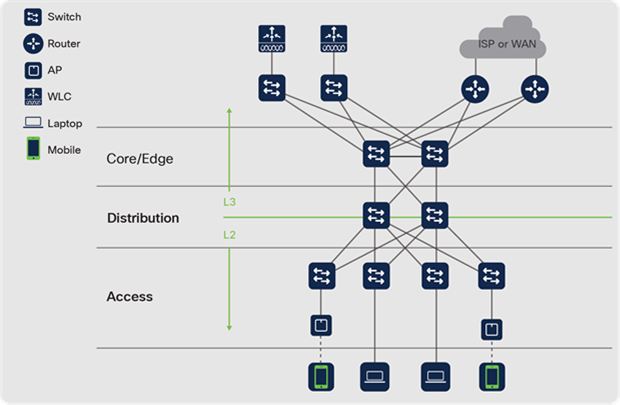
Multi-layer Campus design
Core — The Core layer (3rd tier) in a multi-layer campus design is normally based on L3 IP routing and functions as a high-speed interconnection to other network domains (e.g., DC, WAN, Branch, etc.).
● Edge — Larger campus networks may add another Core Edge layer (4th tier), to add additional resiliency separate complex features and services, such as Virtual Routing and Forwarding (VRF) or Network Address Translation (NAT).
Distribution — The Distribution layer (2nd tier) normally consists of both L3 IP routing to the Core and L2 switching to the Access layer. Distribution blocks function as an aggregation point (reducing fault domains) and serves as a connection point (reducing cabling) between Access wiring closets and Core network.
Access — The Access layer (1st tier) is primarily intended to connect wired and wireless (access point) endpoints and switch their traffic into the rest of the network.
There are several key advantages to this design:
● A tried-and-true design, implemented widely during its > 20-year history
● The hierarchy of layers assigns specific roles and responsibilities
● Scalable and modular. Blocks can be added or removed in any layer, without a major impact on the overall design
● Provides distinct points to add network policies (security, QoS, etc.)
● The L3/L2 boundary can be moved to span VLANs (L2 domains) between multiple Access wiring closets if needed
There are some notable disadvantages to this design. The Distribution layer, in particular, introduces complexity due to its role as an L2-L3 interchange. L2 (LAN) networks are flood domains for Broadcast, unknown Unicast and Multicast (BUM) traffic, and they are subject to loops during link failures and reconvergence.
If not configured correctly: L2 networks may fail when BUM traffic consumes all processing resources, or a network loop blocks links, as the participating L2 switches reconverge. Features such as STP guards, Rapid per-VLAN Spanning Tree (RPVST), IGMP snooping and storm-control can be used to handle these situations, but IT staff must enable, tune and monitor these features.
Note: There are many different L2 and L3 protocols, each with unique requirements and behaviors, but the above design principles are true for all of them.
Catalyst 9000 switches also support the capability to customize SDM templates to optimize ASIC resources for the specific roles of each layer.
Catalyst 9500 and Catalyst 9600-SUP1 models using the UADP 3.0 ASIC, with an SDM template are designed for medium to large Core or Distribution layers. Catalyst 9500X and Catalyst 9600X-SUP2 models using the new Silicon One Q200 ASIC, with an SDM template are designed for larger Core or Edge layers. The key differences are L2/L3 scale, port speed, density and modular High Availability.
| The bottom line |
| Catalyst 9500 and 9600-SUP1 models are optimized for the Core and Distribution layers. Catalyst 9500X and 9600X-SUP2 models have been enhanced for large Core and Edge layers. |
Catalyst 9200, 9300 and 9400-SUP1 models use variations of the UADP 2.0 ASIC and SDM template designed for the Access layer. Catalyst 9300X models use a new UADP 2.0sec ASIC and Catalyst 9400X-SUP2 uses a new UADP 3.0sec ASIC, both with an SDM template designed for a large Access layer or small Distribution or Core layers.
Catalyst 9200 and 9300 Series switches are a stackable fixed form-factor, ideal for switch-level redundancy. Catalyst 9400 Series switches are modular, providing the highest levels of network availability with supervisor, line card and power redundancy. All three switching series support small, medium and large wiring closets.
| The bottom line |
| Catalyst 9200, 9300 and 9400-SUP1 models are optimized for the Access layer. Catalyst 9300X and 9400X-SUP2 models have been enhanced for small Distribution or small Core layers. |
Collapsed Core design
A 2-tier Collapsed Core design is based on the same principles of a traditional (3-tier) multi-layer design, scaled for a small campus network, where both the Core and Distribution layers have been collapsed into a single layer.
Collapsed Core design has all of the advantages of a multi-layer design and requires fewer network devices. This makes it a right-size and cost-effective solution for small sites.
The same drawbacks of multi-layer design also apply to Collapsed Core. In particular, the distribution layer L2/L3 complexity has now been added to the L3 Core, and the bandwidth, scale and port density must cover both layers.
Catalyst 9500 and 9600 switch models use a common set of ASICs, built for Core or Distribution. The key differences are port speed, density and modular High Availability. The SDM template of the Collapsed Core switch may need to be changed from the default (Distribution SDM) to one optimized for the L3 routing scale (Core SDM).
| The bottom line |
| Catalyst 9500 and 9600 models are optimized for large Collapsed Core layers. Catalyst 9500X and 9600X models have been enhanced for large Core and Edge layers. |
There are no changes to the access layer in this design, and the recommendations for Catalyst 9200, 9300 and 9400 Series switches in these roles still apply.
| The bottom line |
| Catalyst 9200, 9300 and 9400 models are optimized for the Access layer. Catalyst 9300X and 9400X models have been enhanced for small Collapsed Core layers. |
Routed Access design
A Routed Access design uses the same physical 2 or 3-tier topology as a traditional multi-layer design. The difference is the placement of the L2 and L3 boundaries. As the name implies, the L3 boundary moves down to the Access layer. VLANs are now contained within each Access switch, and the switches now connect upstream to the Distribution or Core using L3 routed uplinks.
Routed Access design has several benefits:
● Reduces deployment and management complexity, as all links are L3 routed with consistent configurations
● Eliminates 802.1Q trunks, STP and first-hop routing protocols between layers
● Simplifies network operation and troubleshooting, since a single control plane protocol manages network behavior
● Limits failure domains, by moving L2 VLANs to only the Access layer and isolating STP to individual switches
● Allows better utilization of available network paths, as L3 routed networks do not impose STP blocking and instead use Equal-Cost Multi-Paths (ECMP).
Routed Access design does have some drawbacks. It is not possible to span VLANs across a campus network, which restricts client mobility. While best practice designs try to reduce large L2 domains, it is sometimes necessary to connect client applications that only operate using L2 protocols (e.g., mDNS). Also, if ACLs are used, they must be configured on each Access switch, rather than centrally at the Core or Distribution.
A Routed Access network uses the same topology as a traditional multi-layer design. Thus, the positioning of Catalyst 9000 switching platforms remains the same.
| The bottom line |
| Catalyst 9000 switches fully support L3 Routed Access networks, with flexible SDM templates. |
Campus Branch
Extending the main enterprise campus environment to remote branch office locations gives employers and employees greater flexibility while enhancing productivity and reducing costs. Many business and industry verticals have some concept of remote (or branch) office locations, with similar needs as their main campus locations.
While there are many Branch design variations, most follow a simple 1 or 2-tier multi- layer design, scaled for the requirements of a small branch office. As with Collapsed Core, this reduces the number and cost of devices but means collapsing the L2 switching and L3 routing design. The key differences between a 2-tier or 1-tier branch design are based on bandwidth, scale, port density and redundancy:
● Large branches — may use a 2-tier design, with a separate L2/L3 boundary on the Branch Core and L2 in the Branch Access, and small to medium scale. If there are enough access users and devices, then it may be desirable to deploy multiple standalone Access switches or to use stacking or a modular chassis.
● Small branches — may use a 1-tier design, with low to small scale. Now the L2/L3 boundary is on this single device, usually with L3 routed uplinks and L2 switched downlinks. If a small branch may grow, then stacking or a modular chassis can be used.
Since Campus Branch deployments are generally low port density and scale, many customers use Catalyst 9200, 9300 and 9400 Series switches. The key differences are again based on bandwidth and scale and critical Cisco IOS XE features. For this reason, Campus Branch deployments are often separated into:
● Simple Branch — low scale, common L2 capabilities (e.g., VLANs, 802.1Q, STP), basic L3 capabilities (e.g., FHRP, Stub IGP routing), basic overlay support (e.g., SD-Access Edge), basic security (e.g., 128-bit MACsec, PACL, VACL, 802.1X), limited analytics and services (e.g., SPAN, FNF), limited PoE, limited mGig, limited stacking, with fixed or modular uplinks and power supplies.
● Secure Branch — medium scale, advanced L2 (e.g., REP, Selective QinQ), full L3 (e.g., IGP routing, BGP, NSF/NSR, GIR), full overlay support (e.g., SD-Access Edge, Border, Fabric-in-a-Box and embedded WLC, BGP-EVPN, MPLS/VPLS) comprehensive security (e.g., 256-bit MACsec/IPsec, SGACL/OGACL, ETA), leading analytics and services (e.g., ERSPAN, AVC/NBAR2, EPC/Wireshark, App Hosting/ThousandEyes, AI Network Analytics), full UPOE+, full 10GBASE-T, improved stacking, increased High Availability (xFSU, StackPower) with multiple modular uplinks and power supply options.
Catalyst 9200 Series switches with the UADP 2.0 mini ASIC, are primarily built for the Simple Branch access layer. Catalyst 9300 models with UADP 2.0 and 2.0XL or Catalyst 9300X models with UADP 2.0sec are built for the Secure Branch access layer.
For a 2-tier branch, you may choose to use a Catalyst 9300 or 9400 switch as the Branch Core.
| The bottom line |
| Catalyst 9200, 9300 and 9400 switches fully support Campus Branch networks. |
Campus Wireless
Catalyst 9000 switches provide a variety of unique capabilities and innovations to deliver both wired and wireless LAN access.
802.11 Wireless LANs (also known as Wi-Fi) are an access layer technology. Wi-Fi is fast becoming the default choice for users to connect their client machines. People want to move about and take their computers and phones with them. For users, mobility is a powerful tool for productivity and efficiency.
Modern wireless deployments can now offer link speeds comparable to, or even over, what may be available on the wired infrastructure. Wireless deployments using Wi-Fi 6/6E (802.11ax) and 802.11ac Wave 2 now provide MultiGigabit wireless link speeds.
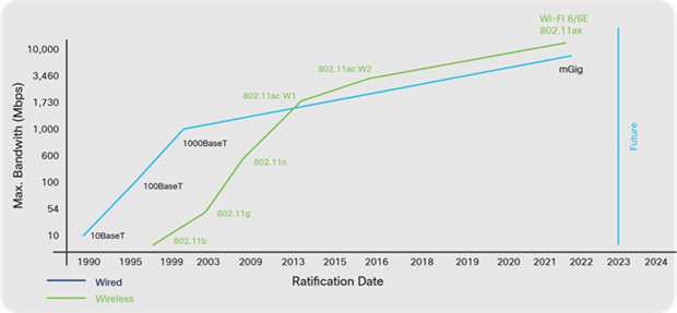
Wired and wireless evolution
Businesses recognize these mobility trends and are transitioning to wireless-only offices, to optimize their IT budgets and achieve the right balance between mobile and fixed endpoints. Businesses must also realize that this trend to wireless access also requires a more flexible wired infrastructure.
| The bottom line |
| As Wi-Fi 6 and 6E adoption grows, switches must support higher speeds such as mGig, 25G or 100G. |
In a multi-layer campus design, a centralized wireless network uses a Wireless LAN Controller (WLC). WLCs usually connect at either the Campus Distribution or Core layer, in a service block connected to the Core, or even a remote data center. Wireless Access Points (APs) connect to the Access layer switches, normally using PoE and high- speed copper cables.
In this design, the WLC becomes the central point-of-management. All configuration and monitoring of wireless APs take place on the WLC. Traditionally, APs then tunnel all data traffic they receive to the WLC (CAPWAP), requiring it to make all forwarding and policy decisions. In other words, the WLC becomes the L2 wireless access boundary, which is connected to a local L3 routing border. This technique allows wireless clients to L2 roam between APs but appear to the network as if they are connected within the same L3 subnet.
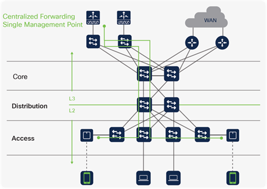
Centralized WLAN design
A centralized wireless network design enables IT staff to configure hundreds of APs from a single management point. A centralized design also helps solve the roaming challenges of 802.11 networks. Instead of extending wireless networks across L3-routed boundaries, a WLC consolidates them at a single place in the network.
One challenge with this approach is that wireless LANs are managed separately from the rest of the wired network. Ideally, administrators should be able to define a single policy for all endpoints and for the policy to be enforced the same way, regardless of the access medium. This causes unnecessary duplication of effort and potential configuration errors.
Another shortcoming is network scale. When APs forward all data to central WLCs, the controllers must be able to handle the entire traffic load. This was not a problem when APs were connecting a small number of clients at 10 or 100 Mbps rates. With the adoption of Wi-Fi 6/6E and 802.11ac Wave 2, WLCs must now use multiple 10G or 40G links to keep up with thousands of clients that connect at > 1 Gbps rates. This also requires higher port speeds and greater port density of the switches connected to the WLC.
| The bottom line |
| Catalyst 9000 switches are optimized to support campus wireless networks. |
Note: Cisco SD-Access offers an innovative new approach for both wired and wireless LAN deployments. SD-Access wireless retains the benefits of centralized wireless management and mobility while adding common policy and scale.
Traditional multi-layer networks have many challenges when it comes to extending L2 domains, maintaining segmentation between endpoints and providing flexibility of scale and the expanding network footprint. In a traditional design, these challenges come with dependencies on traditional protocols such as STP and other networking constructs such as VLANs which are not scalable and are prone to configuration errors.
To overcome these challenges, multiple virtual (tunneled) overlay networks can be built on top of the existing physical (or underlay) network, using network virtualization protocols and constructs such as Virtual Routing and Forwarding (VRF) and tunneling protocols (e.g., VXLAN, LISP and LDP) to provide the needed flexibility, scalability and security.
All overlay technologies have a common set of attributes:
● An underlay network based on a multi-layer design
● Separate overlay control plane and data plane protocols
● Specific roles and functions for overlay devices
This section covers the following overlay solutions for Campus networking and their unique advantages:
● Campus MPLS
● Campus EVPN
● Software-Defined Access (SD-Access)
Campus MPLS
The Campus MPLS design builds upon the previous network designs and delivers virtual segmentation of routing domains. In a multi-layer campus, MPLS extends from the L2/L3 routing boundary, at either Core, Distribution or Access (with Routed Access).
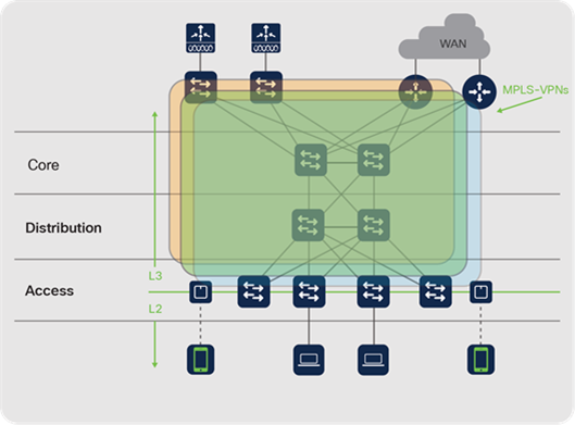
Campus MPLS design
The main advantage of MPLS-VPN in Campus is to provide macro-level network segmentation, along with L2 extensions, using VRF instances and LDP labels to make forwarding decisions within an MPLS network. MPLS networks also allow IT staff to manipulate MPLS behavior, to improve the efficiency of label switching and steer traffic through the network (called traffic engineering, or MPLS-TE) to optimize available paths.
MPLS is also capable of supporting additional IP Services such as Multicast traffic in Overlay via Multicast Label Distribution Protocol (MLDP) along with other scalable mechanisms such as Seamless MPLS and Hierarchical VPLS.
However, MPLS adds complexity and additional overhead in the control plane (LDP for label distribution, MP-BGP for VPN distribution and RSVP to signal MPLS-TE tunnels). Creating and managing multiple, virtual routing domains requires complex engineering and IT staff must also understand MPLS protocols and be able to troubleshoot multiple, concurrent virtual routing instances.
Catalyst 9000 switches support MPLS, and the same recommendations apply as a routed access network, with the addition of MPLS feature support. Catalyst 9500 and 9600 Series switches are designed for Distribution and Core layer services, while Catalyst 9300 and 9400 Series switches are best suited as access devices.
Note: Note Catalyst 9200 Series switches do not support MPLS.
| The bottom line |
| Campus MPLS provides a standardized overlay network to provide L2/L3 VPN services. All business-critical Catalyst 9000 switches are optimized for Campus MPLS networks. |
Note: Enterprise requirements for segmentation are becoming more stringent. Although MPLS-VPN provides L2/L3 macro-segmentation (separate VRF domains), it does not address micro-segmentation (access control policies).
Campus EVPN
The Campus EVPN design also builds upon previous network designs and constructs to deliver virtual separation of network segments. In a multi-layer campus, EVPN extends from the L2/L3 routing boundary, at either Core, Distribution or Access (with Routed Access).
The main advantage of BGP EVPN in Campus is that it provides segmentation flexibility, using L2 or L3 VXLAN Network Identifiers (VNI). It not only provides macro-level L3 segmentation using VRF, but also extends L2 (VLAN) domains across the network, over a L3 Underlay. It also provides seamless mobility for endpoints with the concept of Anycast L3 Gateway, where the same IP/mask subnet can span across all Access (also known as leaf) Virtual Tunnel Endpoints (VTEPs).
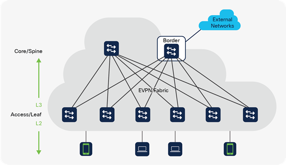
Campus EVPN design
EVPN also provides the flexibility to design different overlay topologies (Point-to-Point, Point-to-Multipoint, Hub-n-Spoke, etc.) and implement resiliency via either StackWise Virtual or ESI-based Multi-Homing. BGP EVPN leverages Tenant Routed Multicast (TRM) to optimize and scale Multicast traffic (L3TRM for routed Multicast and L2TRM for Layer 2 Multicast). EVPN implementation on Catalyst 9000 switches has a tight integration with other services like SD-Bonjour to further eliminate the mDNS flood domain and interoperates with private VLAN’s to provide more granular segmentation.
Catalyst 9000 switches running IOS XE support campus BGP EVPN and similar recommendations apply like the previous solution with routed access design. Catalyst 9500 and 9600 switches are designed for Spine/Border Services, while Catalyst 9300 and 9400 Series switches are best suited for VTEP or Edge services. Catalyst 9200 Series switches do not support BGP EVPN.
| The bottom line |
| Campus EVPN provides a standardized overlay network to provide L2/L3 VNI services. All business-critical Catalyst 9000 switches are optimized for Campus EVPN networks. |
Note: Although Campus EVPN does meet many campus requirements for L2/L3 macro segmentation, but like Campus MPLS, it does not address micro-segmentation.
Software-Defined Access
Cisco's Software-Defined Access (SD-Access) segmentation solution is a flexible, programmable network architecture that provides software-based policy and segmentation at the macro and micro levels for both wired and wireless endpoints. Cisco SD-Access is implemented via Cisco DNA Center which provides design settings, policy definition and automated provisioning of wired, wireless and security network elements, as well as AI/ML-based assurance analytics for all network elements.
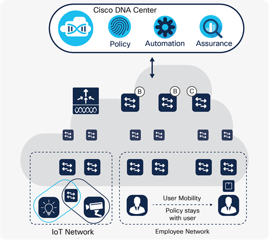
Cisco SD-Access solution
Cisco SD-Access creates a virtual overlay fabric network based on LISP and VXLAN to provide host mobility, segmentation and group-based policy, regardless of the location on campus, completely automated and assured by Cisco DNA Center.
SD-Access is similar to Campus EVPN and provides segmentation using L2 or L3 VXLAN Network Identifiers (VNI) to enable macro-level L3 segmentation and extends L2 (VLAN) domains across the network. It also leverages Distributed Anycast L3 Gateway to provide seamless mobility for endpoints.
SD-Access has been designed specifically for enterprise networks. In addition to the full automation and assurance provided by Cisco DNA Center, SD-Access provides micro- level segmentation using Source Group Tags (SGT) to enable Group-Based Policy (SGACL, QoS and PBR). The other key advantage of SD-Access is common automation, assurance and policy for Campus Wireless.
Cisco SD-Access wireless
Cisco SD-Access treats wireless data the same as wired data. This approach enables a common policy across both access methods. The control plane of the wireless network and AP management remain centralized (on the WLC), but the wireless data plane uses a distributed model via the switch infrastructure.
Instead of tunneling all wireless client traffic to the WLC, each AP constructs a VXLAN tunnel directly to the fabric edge switch it is attached to. The switch terminates this traffic and then provides full treatment for the wireless traffic just as it would for wired traffic, including macro and micro-segmentation based on VNIs and SGTs.
Some of the key SD-Access wireless benefits are:
● Centralized control plane — Wireless management, AP management, RRM, client onboarding and roaming are controlled by Cisco DNA Center
● Distributed data plane — Wireless data traffic is distributed to the fabric edge switches, for optimal network performance and scale
● Seamless L2/L3 roaming — Clients can roam seamlessly within VNIs stretched across a campus while retaining the same IP address and group policy
● Policy simplification — SD-Access breaks the dependency between policy and network constructs and manages wired and wireless endpoints consistently
For more information about Cisco SD-Access Wireless, refer to cisco.com/go/wirelessebook
Catalyst 9500/9500X and Catalyst 9600-SUP1/9600X-SUP2 models can leverage specific SDM templates for SD-Access border or control plane nodes. The key differences are L2/L3 scale, port speed, density and modular High Availability.
| The bottom line |
| Catalyst 9500 and 9600-SUP1 switches are optimized for SD-Access border and control plane nodes. Catalyst 9500X and 9600X-SUP2 switches have been enhanced for larger border and control plane nodes. |
Catalyst 9200, 9300 and 9400-SUP1 models use variations of the UADP 2.0 ASIC with an SDM template designed for SD-Access Edge nodes. Catalyst 9300X models use a new UADP 2.0sec ASIC and 9400X-SUP2 models use a new UADP 3.0sec ASIC, both with an SDM template designed for a large Access layer or small SD-Access Border nodes.
Catalyst 9200 and 9300 Series switches are a stackable fixed form-factor, ideal for switch-level redundancy. Catalyst 9400 Series switches are modular, providing the highest levels of network availability with supervisor, line card and power redundancy. All three switching series support small, medium and large SD-Access Edge designs.
| The bottom line |
| Catalyst 9200, 9300 and 9400-SUP1 models are optimized for SD-Access Edge nodes. Catalyst 9300X and 9400X-SUP2 models have been enhanced for small SD- Access Edge nodes. |
For more information about Cisco SD-Access, refer to cisco.com/go/sdaccessoverview
Additional websites which offer more detailed information about the Catalyst 9000 Switching Family and its capabilities:
Overview of the Cisco Catalyst 9000 Family of Switches
cisco.com/c/en/us/products/switches/catalyst-9000.html
Overview of Cisco Catalyst 9000 switches
Cisco Catalyst 9000 switching white paper
cisco.com/c/en/us/products/switches/catalyst-9200-series-switches/white-paper-listing.html
cisco.com/c/en/us/products/switches/catalyst-9300-series-switches/white-paper-listing.html
cisco.com/c/en/us/products/switches/catalyst-9400-series-switches/white-paper-listing.html
cisco.com/c/en/us/products/switches/catalyst-9500-series-switches/white-paper-listing.html
cisco.com/c/en/us/products/switches/catalyst-9500-series-switches/white-paper-listing.html
Cisco Live On-Demand Library
ciscolive.com/global/on-demand-library.html
BRKPRG-2451: Scripting IOS XE beyond the basics
BRKENS-2004: Catalyst 9000 IOS XE Innovations
BRKARC-2035: The Catalyst 9000 Switch Family – an architectural view
BRKARC-3467: Cisco enterprise silicon - delivering innovation for advanced routing and switching
BRKARC-1343: Catalyst 9200 Overview and architecture
BRKARC-3863: Catalyst 9300 Series switching architecture
BRKARC-3873: Catalyst 9400 Series switching architecture
BRKARC-2007: Catalyst 9500 Series switching architecture
BRKARC-3010: Catalyst 9600 Series switching architecture
BRKCRS-2810: Cisco SD-Access — A Look Under the Hood
DevNet, the Cisco Developer Network
developer.cisco.com/site/ios-xe
developer.cisco.com/yangsuite/
Video Resources
Application Hosting with Catalyst 9000 Demo
Under the hood of the Catalyst 9000X
Meet the Catalyst 9300X Switches
Meet the Catalyst 9400X Switches
Meet the Catalyst 9500X and 9600X Switches
The Future of Real Estate for Hybrid Work
Catalyst 9000 automation
Cisco DevNet Code Exchange: developer.cisco.com/codeexchange/
Cisco DevNet Automation Exchange: developer.cisco.com/network-automation/
Terraform Infrastructure as Code: github.com/CiscoDevNet/terraform-provider-iosxe/
blogs.cisco. com/tag/sustainability
blogs cisco.com/tag/smartbuildings
AAA - Authentication, Authorization and Accounting
AC - Alternating Current
ACK - Acknowledgment
ACL - Access Control List
AES - Advanced Encryption Standard
AGS - Advanced Gateway Server
AI - Artificial Intelligence
AOC - Active Optical Cables
AP - Access Point
API - Application Programming Interface
AQM - Active Queue Management
AR - Augmented Reality
ARM - Advanced RISC Machines
ARP - Address Resolution Protocol
ASIC - Application-Specific Integrated Circuit
ASLR - Address Space Layout Randomization
AVB - Audio Video Bridging
AVC - Application Visibility and Control
AWS - Amazon Web Services BC - Boundary Clock
BGP - Border Gateway Protocol
BGP-EVPN - Border Gateway Protocol Ethernet Virtual Private Network
BOOTP - Bootstrap Protocol
BPDU - Bridge Protocol Data Units
Bpps - Billion Packets Per Second
BUM - Broadcast, Unknown unicast, and Multicast
BYOD - Bring Your Own Device
CAGR - Compound Annual Growth Rate
CAPWAP - Control And Provisioning of Wireless Access Points
CBAR - Controller-Based Application Recognition
CBWFQ - Class-based Weighted Fair Queuing
CDN - Content Delivery Network
CDP - Cisco Discovery Protocol
CEF - Cisco Express Forwarding
CI/CD - Continuous integration and continuous deployment
CIR - Committed Information Rate
Cisco DNA - Cisco Digital Network Architecture
CLI - Command Line Interface
CoA - Change of Authorization
CoS - Class of Service
CPU - Central Processing Unit
CSMA/CD - Carrier Sense Multiple Access with Collision Detection
CTA - Cisco Trust Anchor
CTA - Cognitive Threat Analytics
DAC - Direct Attach Copper
DAD - Dual-Active Detection
DC - Direct Current
DHCP - Dynamic Host Configuration Protocol
DIY - Do-It-Yourself
DMZ - Demilitarized Zone
DNS - Domain Name System
DPI - Deep Packet Inspection
DSCP - Differentiated Services Code Point
DTA - Dynamic Threshold Algorithm
DTLS - Datagram Transport Layer Security
DTP - Dynamic Trunk Protocol
DTS - Dynamic Threshold Scheduler
E-LLW - Enhanced Limited Lifetime Hardware Warranty
EA - Enterprise Agreement
EAP - Extensible Authentication Protocol
EAPoL - Extensible Authentication Protocol over LAN
ECC - Error-Correcting Code ECMP - Equal-Cost Multipathing
ECN - Explicit Congestion Notification
EEM - Embedded Event Manager
EIGRP - Enhanced Interior Gateway Routing Protocol
EoMPLS - Ethernet Over Multiprotocol Label Switching
EPC - Embedded Packet Capture
EQS - Egress Queuing Scheduler
ERSPAN - Encapsulated Remote Switched Port Analyzer
ESI - Ethernet Segment Identifier
ESP - Encapsulating Security Payload
ETA - Encrypted Traffic Analytics
EVPN - Ethernet Virtual Private Network
FHRP - First Hop Redundancy Protocol
FIB - Forwarding Information Base
FIFO - First In First Out FNF - Flexible NetFlow
FPGA - Field Programmable Gate Array
FQTSS - Forwarding and Queuing for Time-Sensitive Streams
FRU - Field Replaceable Unit
FTP - File Transfer Protocol
Gbps - Gigabits per second
GCM - Galois/Counter Mode
GCP - Google Compute Platform
GIR - Graceful Insertion and Removal
GM - Grandmaster
gNMI - gRPC Network Management Interface
gNOI - gRPC Network Operation Interface
GPE - Generic Protocol Extension
GPO - Group Policy Object
GPS - Global Positioning System
gPTP- Generalized Precision Time Protocol
GRE - Generic Routing Encapsulation
gRPC - Google Remote Procedure Call
GUI - Graphical User Interface
HA - High Availability
HBM - High Bandwidth Memory
HQoS - Hierarchical QoS
HSRP - Hot Standby Router Protocol
HTTP - Hypertext Transfer Protocol
HTTPS - HyperText Transfer Protocol Secure
HVAC - Heating Ventilation and Air Conditioning
HW - Hardware
IaC - Infrastructure as Code
ICS - In-Chassis Standby
IEEE - Institute of Electrical and Electronics Engineers
IETF - Internet Engineering Task Force
IGMP - Internet Group Management Protocol
IGP - Interior Gateway Protocol
IKEv2 - Internet Key Exchange version 2
ILP - Inline Power
IaaS - Infrastructure As A Service
IOS - Internetwork Operating System
IOS XE - Internetwork Operating System extended for Enterprise
IOS XR - Internetwork Operating System extended for Routing
IOSd - IOS Daemon
IoT - Internet of Things
IoX - Application Hosting Framework
IP FRR - IP Fast Re-Route
IPFIX - IP Flow Information Export
IPsec - Internet Protocol security
IPTV - Internet Protocol Television
iPXE - Enhanced Preboot Execution Environment
IQS - Ingress Queuing Scheduler
IS-IS - Intermediate System to Intermediate System
ISE - Identity Services Engine
ISP - Internet Service Provider
ISSU - In-Service Software Upgrade
IT - Information Technology
ITU - International Telecommunication Union
ITU-T - ITU’s Telecommunication Standardization Sector
JSON - JavaScript Object Notation
kW - KiloWatt
L2 - Layer 2 L3 - Layer 3
LACP - Link Aggregation Control Protocol
LAN - Local Area Network LC - Lucent Connector
LDevID - Local Device Identity
LDP - Label Distribution Protocol
LED - Light-Emitting Diode
LEED - Leadership in Energy and Environmental Design
LISP - Locator/ID Separation Protocol
LLDP - Link Layer Discovery Protocol
LPM - Longest Prefix Match
LSC - Locally Significant Certificate
MAB - MAC Authentication Bypass
MAC - Media Access Control
MACsec - Media Access Control security
Mbps - Megabits per second
mDNS - Multicast Domain Name System
MDT - Model-Driven Telemetry
MEC - Multi-Chassis EtherChannel
MFIB - Multicast Forwarding Information Base
mGig - multiGigabit
MKA - MACsec Key Agreement
ML - Machine Learning
MLD - Multicast Listener Discovery
MLDP - Multicast Label Distribution Protocol
MMF - Multimode Fiber
MPLS - Multiprotocol Label Switching
MPLS EXP - MPLS experimental bits
MPLS-TE - MPLS Traffic Engineering
MPO - Multi-fiber Push-On
Mpps - Million Packets Per Second
MQC - Modular QoS CLI
MSB - Most Significant Bits
MSP - Managed Services Provider
MSRP - Multiple Stream Reservation Protocol
MTU - Maximum Transmission Unit
NAT - Network Address Translation
NBAR - Network-Based Application Recognition
NETCONF - Network Configuration Protocol
NIST - National Institute of Standards and Technology
NPU - Network Processing Unit
NSF - Nonstop Forwarding or Non-Stop
NSH - Network Service Header
NSO - Network Service Orchestrator
NSR - Nonstop Routing
NX-OS - Nexus Operating System
OC - Ordinary Clock
OIR - Online Insertion and Removal
OM - Optical Multimode
OQ - Output Queue
OS - Operating System
OSI - Open Systems Interconnection model
OSPF - Open Shortest Path First
OT - Operational Technology
P2P - peer-to-peer
PACL - Port Access Control List
PAgP - Port Aggregation Protocol
PBR - Policy-Based Routing
PDL - Per Device Licensing
PDU - Protocol Data Unit
PE - Provider Edge router
PHY - PHYsical layer
PIR - Peak Information Rate
PMK - Pairwise Master Key
PnP - Network Plug and Play
POE - Power over Ethernet
pps - packets per second
PSU - Power Supply Unit
PTP - Precision Time Protocol
PXE - Preboot Execution Environment
pxGrid - Platform Exchange Grid
QAT - Quick Assist Technology
QoS - Quality of Service
QSA - QSFP to SFP Adapter
QSFP - Quad Small Form-factor Pluggable
QSFPDD - Quad Small Form-factor Pluggable Double Density
RADIUS - Remote Authentication Dial-In User Service
RED - Random Early Discard
REP - Resilient Ethernet Protocol
REST - REpresentational State Transfer
RESTCONF - REST Configuration Protocol
RFC - Request for Comments
RFID - Radio-Frequency IDentification
RIB - Routing Information Base
RNG - Random Number Generators
RPC - Remote Procedure Call
RPR - Route Processor Redundancy
RPVST - Rapid per VLAN Spanning Tree
RRM - Radio Resource Management
RSPAN - Remote Switched Port Analyzer
SaaS - Software-as-a-Service
SAP - Security Association Protocol
SATA - Serial AT Attachment
SD - Software-Defined
SD-Access - Software-Defined Access
SD-AVC - Software-Defined Application Visibility and Control
SD-WAN - Software-Defined Wide Area Network
SDG - Service Discovery Gateway
SDM - Switching Database Manager
SDN - Software Defined Networking
SFP - Small Form-factor Pluggable
SGACL - Scalable Group Access Control List
SGFW - Security Group Firewall
SGT - Scalable Group Tag
SIP - Session Initiation Protocol
SKU - Stock Keeping Unit
SLI - Switch Link Interface
SMC - Stealthwatch Management Console
SMF - Single-Mode Fiber
SMS - Shared Memory Subsystem
SMU - Software Maintenance Update
SNMP - Simple Network Management Protocol
SPAN - Switched Port Analyzer
SPQ - Strict Priority Queuing
SRAM - Static Random-Access Memory
SRP - Stream Reservation Protocol
SSD - Solid-State Drive
SSH - Secure Shell
SSO - Stateful Switchover
ST - Service Template
STP - Spanning Tree Protocol
SUDI - Secure Unique Device Identifier
SVL - StackWise Virtual Link
SW - Software
SWIM - Software Image Management
SXP - SGT Exchange Protocol
TAC - Technical Assistance Center
Tbps - Terabits Per Second
TC - Transparent Clock
TCAM - Ternary Content Addressable Memory
TCO - Total Cost of Ownership
TCP - Transmission Control Protocol
TFTP - Trivial File Transfer Protocol
TLS - Transport Layer Security
ToS - Type of Service
TRM - Tenant Routed Multicast
TTL - Time to Live
UADP - Unified Access Data Plane
UDLD - Unidirectional Link Detection
UDP - User Datagram Protocol
UHD - Ultra High Definition
UHF - Ultra-High Frequency
UI - User Interface
UPoE - Universal Power Over Ethernet
URL - Uniform Resource Locator
USB - Universal Serial Bus
VACL - VLAN Access Control List
VLAN - Virtual LAN
VM - Virtual Machine
VN - Virtual Network
VNI - Virtual Network Instance
VoQ - Virtual Output Queuing
VPC - Virtual Port Channel
VR - Virtual Reality
VRF - Virtual Routing and Forwarding
VRRP - Virtual Router Redundancy Protocol
VSS - Virtual Switching System
VTEP - Virtual Tunnel Endpoint
VTP - VLAN Trunk Protocol
VXLAN - Virtual eXtensible Local Area Network
VXLAN-GPO - Virtual eXtensible Local Area Network Group Policy Option
WAN - Wide Area Network
WDM - Wavelength Division Multiplexing
WebUI - Website User Interface
WFQ - Weighted Fair Queuing
WLC - Wireless LAN Controller
WRED - Weighted Random Early Detection
WRR - Weighted Round Robin
WTD - Weighted Tail Drop
XFP - 10 Gigabit Small Form-factor Pluggable
xFSU - Extended Fast Software Upgrade
XML - Extensible Markup Language
XPN - Extended Packet Numbering
XPS - Expandable Power System
YANG - Yet Another Next Generation
YDK - YANG Development Kit
ZTP - Zero-touch Provisioning