From X440p to X580p. How Cisco is Expanding Modular Server Use Cases (Again) White Paper
Available Languages
Bias-Free Language
The documentation set for this product strives to use bias-free language. For the purposes of this documentation set, bias-free is defined as language that does not imply discrimination based on age, disability, gender, racial identity, ethnic identity, sexual orientation, socioeconomic status, and intersectionality. Exceptions may be present in the documentation due to language that is hardcoded in the user interfaces of the product software, language used based on RFP documentation, or language that is used by a referenced third-party product. Learn more about how Cisco is using Inclusive Language.
In April 2022, a blog was posted announcing support for a new PCIe node called the Cisco UCS® X440p PCIe Node in our Cisco UCS X9508 Chassis. This allowed a traditional blade form factor to take advantage of double-wide, full-height, and full-length GPUs without compromising the simplicity of a modular architecture. Our innovation didn’t stop there. According to the recent Cisco Global AI Readiness Index, 85 percent of the respondents stated they had less than 18 months to deploy an AI strategy or could recognize negative business benefits if that timeline wasn’t met. Within that study, 50 percent of the companies stated that 10 to 30 percent of their budgets was already dedicated to AI. These insights can help us develop products that will not only meet industry demand but also help customers who are facing tight timelines or customers that could be faced with the complexities seen in newer innovations. Some of those innovations we are going to cover in this paper include the recent addition of the Cisco UCS X580p PCIe Node and Cisco UCS X9516 X-Fabric module to the Cisco UCS X-Series Modular portfolio.
UCS X-Series with X580p and X9516 managed by Intersight
Before we dive deeper into the next-generation PCIe support in the Cisco UCS X-Series servers, let’s take a look at why GPUs in modular servers are important. When Cisco first announced the Cisco UCS X440p PCIe Node,customers may have focused on workloads like graphics-accelerated VDI use cases or AI Inferencing.
When you think back to what was happening in the AI industry at that time, generative AI was starting to ramp up. Companies may have started adopting the use of publicly available LLMs and fine tuning them for various usecases or projects as they continued to learn about the benefits of AI for the enterprise.
Let’s start with a level foundation. Deploying AI infrastructure can be complex. The core value proposition that blades brought to the market (reduced cabling, power and cooling efficiencies, fast upgrades, etc.) can now be recognized for more specialized workloads, given the innovations we are bringing to market with the Cisco UCS X-Series portfolio.
As many are aware, Cisco UCS modular servers have traditionally operated with a north/south fabric that included a pair of top-of-rack “Fabric Interconnects” (FIs) paired with a fabric extender in our chassis call “Intelligent Fabric Modules” (IFM). This “unified fabric” gave customers the flexibility they needed to significantly reduce the cabling footprint of the data center by consolidating Fibre Channel, Ethernet, and management traffic onto a single wire to the server. The server had a specialized card called a Cisco® Virtual Interface Card (VIC), which could be programmed to present different PCIe network devices (vHBAs/vNICs) for various host use cases.
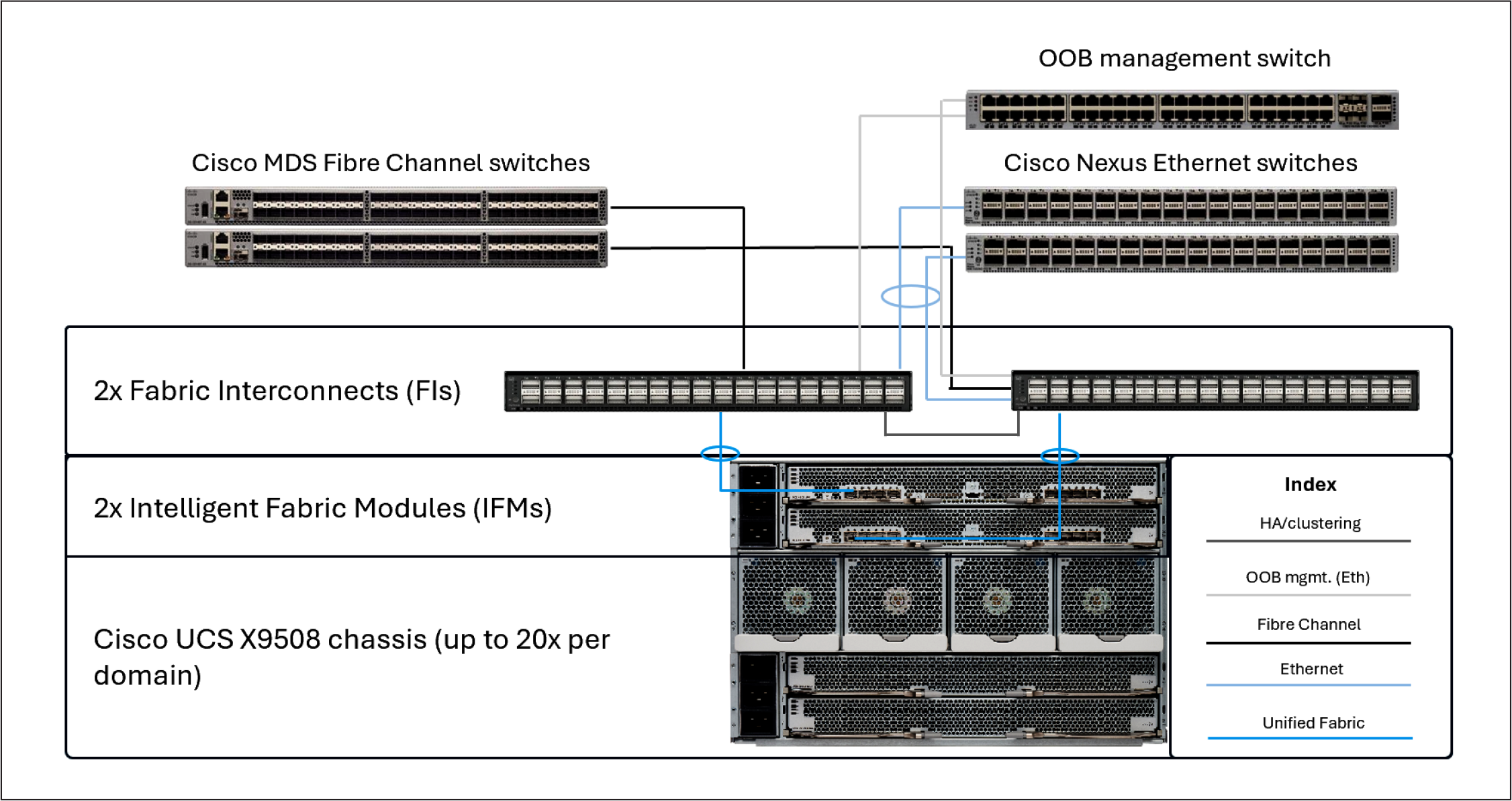
Cisco UCS domain cabling example
Simplicity is the future, and the future is now
Fast forward to today. With the Cisco UCS X580p PCIe Node and Cisco UCS X9516 X-Fabric, let’s now discuss the next evolution of modular server computing. This new paradigm will allow customers who have adopted those newer workloads that require components such as NVLink-Bridged GPUs and a separate east/west backend fabric to deploy these workloads in a modular server form factor without sacrificing the simplicity, modularity, efficiency, and serviceability they have recognized in historical modular server use cases. This innovation allows customers to adopt a different approach to deploying infrastructure by disaggregating the GPU and SmartNIC from the typical PCIe slots that reside on a server and allowing resources to be provisioned by leveraging the UCS X580p and UCS X9516 X-Fabric. If a customer wants to test a workload on an Intel® platform today (for example, a Cisco UCS X210c M8 Compute Node), they can provision one, two, or four GPUs to the host via policy and perform their tests.
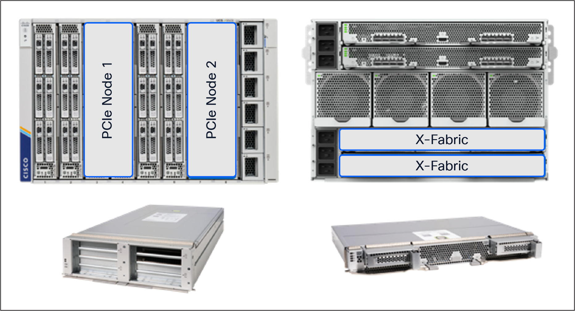
Slot Population Example
With the Cisco UCS X440p PCIe Node, a server can have a maximum of 2x PCIe Gen4 GPUs positioned next to the node within the chassis. With the Cisco UCS X580p PCIe Node, we can now provision up to 4x PCIe Gen5 GPUs including GPUs that leverage NVIDIA’s NVLink 2-way bridge to a server residing in the same PCIe zone within the chassis.
This new design allows customers to consider various deployment scenarios that were not available in previous platforms. When a customer combines the Cisco UCS X9516 X-Fabric and Cisco UCS X580p PCIe Node with the Cisco UCS X210c M8 or X215c M8 compute nodes, they can now provision GPUs and SmartNICs via policy. One, two, or four GPUs and one to two SmartNICs can be assigned to a server through a new Cisco Intersight® PCIe connectivity policy that will be discussed later in this document. This allows customers to have a much more flexible, adaptable, and disaggregated infrastructure as workloads and resource demands change throughout the server lifecycle.
Modular server connectivity to an external AI fabric
As mentioned earlier, backend fabrics are independent of the typical 25GbE/100GbE frontend networks traditionally leveraged for server data communications. To enable this line of separation, we needed to allow modular servers to support additional high-bandwidth NICs independent of the frontend network connectivity.
This functionality is enabled by installing a pair of Cisco UCS X9516 X-Fabric Modules (XFMs) into the bottom two slots in the back of the Cisco UCS X9508 Chassis. The new XFMs have PCIe switches to allow for GPU and SmartNIC provisioning to servers in the chassis using Cisco Intersight (Cisco’s SaaS-based management platform) to manage the configuration.
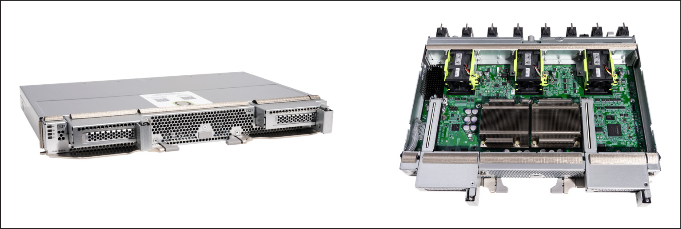
X9516 X-Fabric Module
Global management and monitoring
To simplify the deployment and provisioning of PCIe devices to Cisco UCS X-Series servers, we have added a new Intersight policy that can easily be attached to server profiles or server profile templates. This policy allows for the flexibility customers have come to expect from our modular platforms by leveraging our policy-driven management model. Not only will Intersight be used to provision the devices, but customers can also monitor various metrics deemed important to performance of the computing infrastructure.
As with any server deployment, some planning is required to ensure that placement of GPUs and NICs is in line with the desired outcome. Given that the Cisco UCS X-Series is managed through Cisco Intersight, systems administrators will be able to take advantage of the policy model that Intersight leverages to simplify deployment at scale.
Before we dive deeper into creating a PCIe connectivity policy in Intersight and applying the policy to a server profile, let’s review a graphical representation of a potential PCIe mapping with different configurations within the chassis. Figure 5 shows the allocation of GPUs and SmartNICs to various hosts in the Cisco UCS X9508 Chassis.
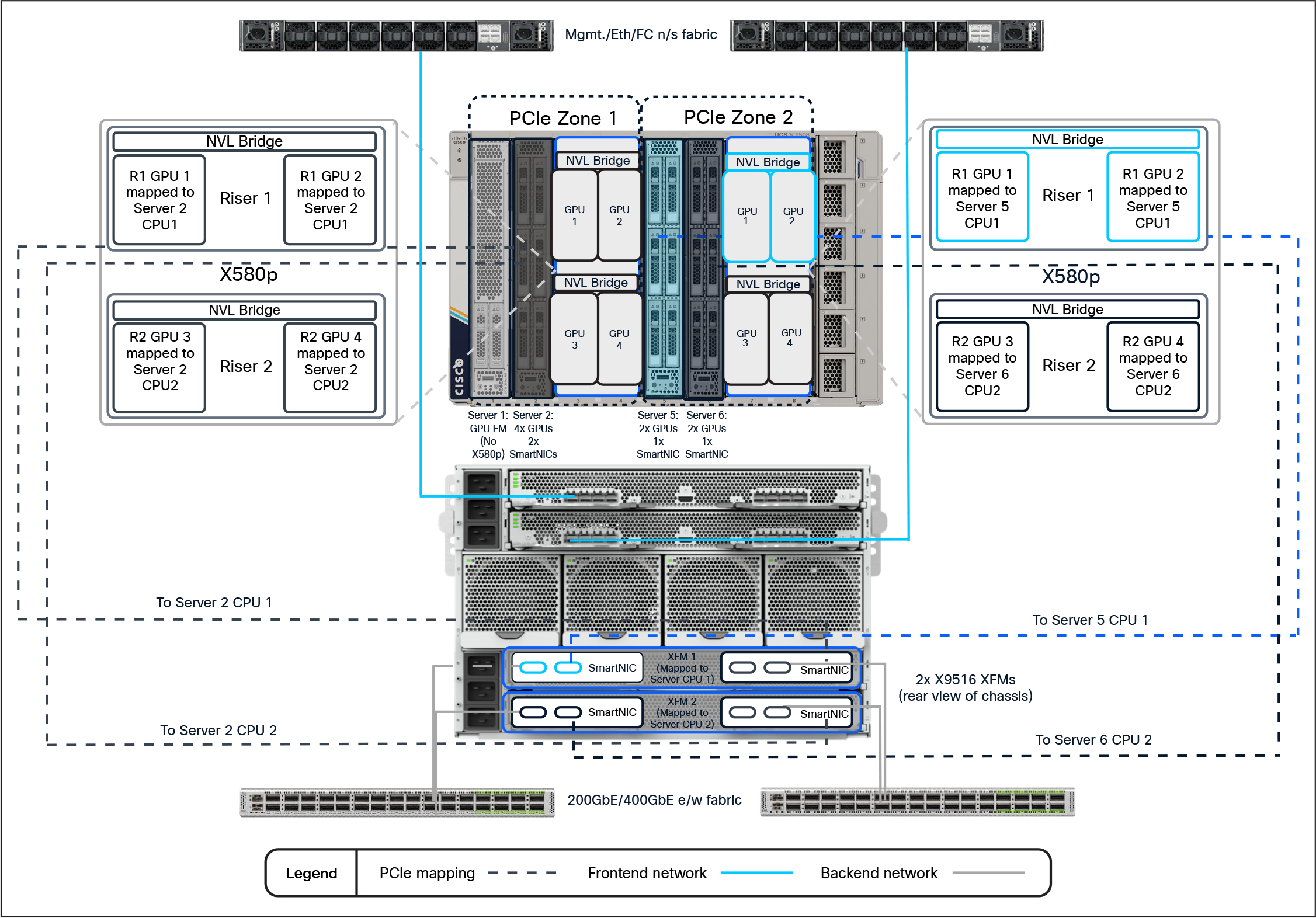
UCS X-Series PCIe Mapping Example
Hardware overview
At launch, the existing Cisco UCS X9508 Chassis supports the new Cisco UCS X580p PCIe Node (UCSX-580P) and Cisco UCS X9516 X-Fabric (UCSX-F-X9516) modules paired with Cisco UCS X210c M8 or X215c M8 compute nodes. The servers will need the new PCIe Gen5 mezzanine card (UCSX-V5-PCIME) to communicate with the X9516 X-Fabric modules. Also at launch, the X580p supports the NVIDIA L40S, H200-NVL, or RTX Pro 6000 GPUs. Given that the GPUs are populated side by side in each cage, the X580p also supports the two-way NVLink Bridge attached to the NVIDIA H200-NVL GPUs. The X9516 also supports NVIDIA’s ConnectX-7 SmartNICs. Customers may choose either a 2x200GbE CX-7 or a 1x400GbE CX-7.
Intersight policy overview
To take advantage of PCIe devices installed in the X580p and X9516, we must first define a PCIe connectivity policy and attach it to either the server profile or server-profile template in Intersight. There are several considerations we must account for when planning deployment of resources in a large-scale environment. Given that there are 2x PCIe Zones within a chassis, we want to make sure our GPUs/NICs that we are assigning will be on the same root complex/CPU socket to achieve maximum performance.
Deployment strategy considerations
When deciding how you want to use PCIe devices with Cisco UCS X-Series, it’s best to remember the old saying, “Proper planning prevents poor performance.” The same is true with PCIe connectivity.
The best practice for GPUs and NICs is to make sure you have them on the same PCIe root complex (that is, the same CPU socket). Each XFM has a pair of PCIe switches that are associated with a respective socket in the server (for example, XFM-1 -> host CPU-1, XFM-2 -> host CPU-2). This allows us to define the server’s PCIe assignment through a policy in Intersight to maintain best practices when deploying GPUs and NICs to a server.
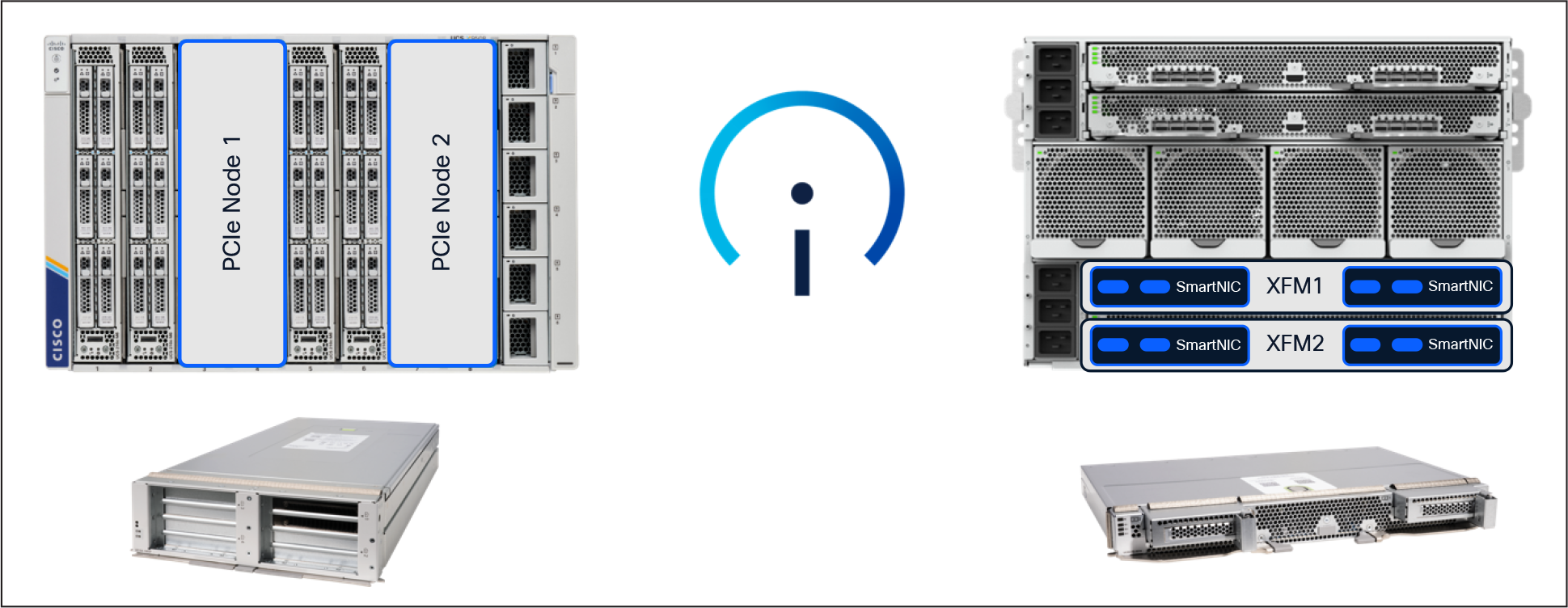
Figure 6 shows an example of 2x hosts, each with 2x NVLink-bridged GPUs and 1x SmartNIC attached through a policy
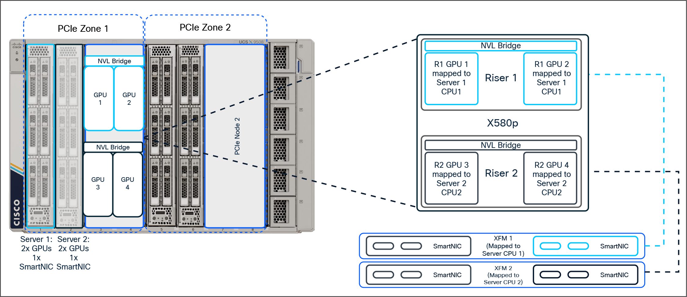
2x GPUs and 1x SmartNIC per node deployment example
With Intersight, customers can create or modify an existing BIOS policy to include a new BIOS token introduced with the new platforms. To leverage the new token, navigate to Configure -> Policies and create a new (or modify an existing) BIOS policy. Under “Main,” customers will see the new tokens (platform default is disabled):
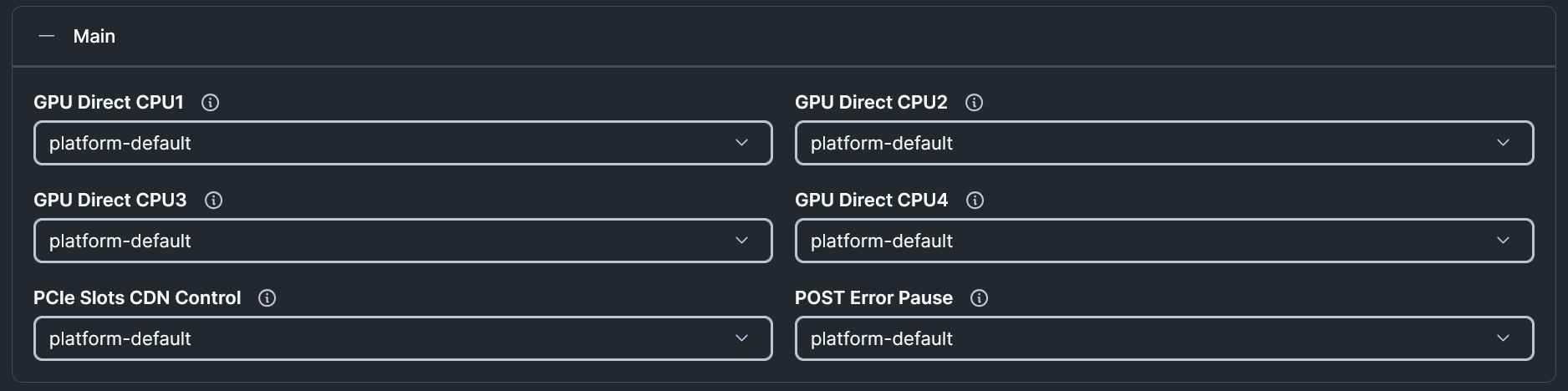
GPU Direct BIOS Policy Settings
From Intersight, you can navigate to Configure -> Policies and create a new PCIe Connectivity Policy. Within that policy, you will create an “End Point Mapping” for each CPU socket. If 2x GPUs and 1x NIC are required, you can create a single mapping. If 4x GPUs and 2x NICs are required, you will then create 2x mappings (1x mapping for CPU 1 and 1x mapping for CPU 2). The first mapping will define the number of GPUs, the GPU type, and the NIC type you wish to map to the CPU socket of the host. Adding a second mapping under the policy details will inherit the same GPU and GPU quantity as the first mapping, but on the alternate CPU socket. Optionally, you can add 1 SmartNIC to each End Point Mapping.
Figure 8 shows a PCIe Connectivity Policy configuration for adding 4x GPUs and 2x SmartNICs to a host once the policy has been applied.
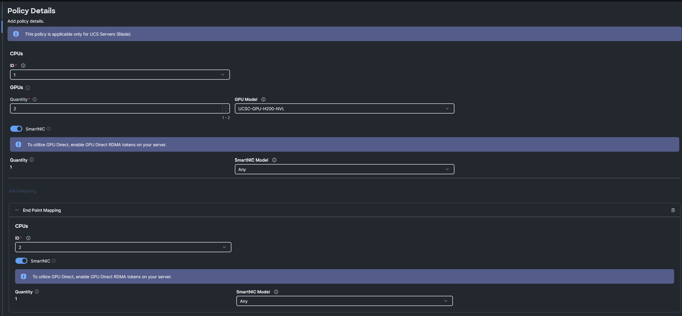
PCIe Connectivity Policy example
Server Profile/Server Profile Template Policy addition
Once you have completed the steps required for creating the new PCIe Connectivity Policy, it is time to attach that policy to an existing Server Profile/Server Profile Template or create a new profile/template. The new policy can be selected from the Compute Configuration section of the profile/template configuration steps, as shown in Figure 9.
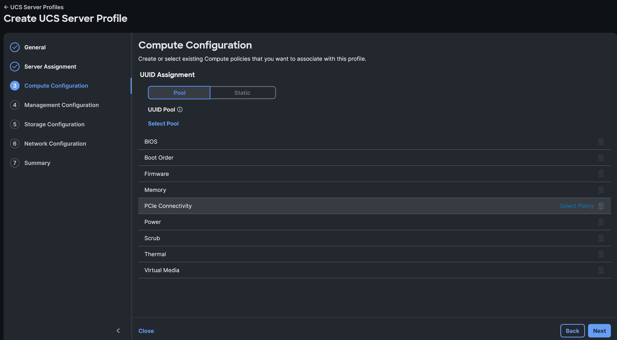
UCS Server Profile PCIe Connectivity policy selection example
Server Inventory with Mapped PCIe Devices
After a profile with a PCIe Connectivity Policy has been deployed to a server, you can verify the devices mapped in several locations within Intersight. First, navigate to the server inventory and expand the CPUs. From the the CPU view, you can see a new tab called “Mapped PCIe Devices”. As shown in the example below, the server has 2x GPUs mapped to processor 1:
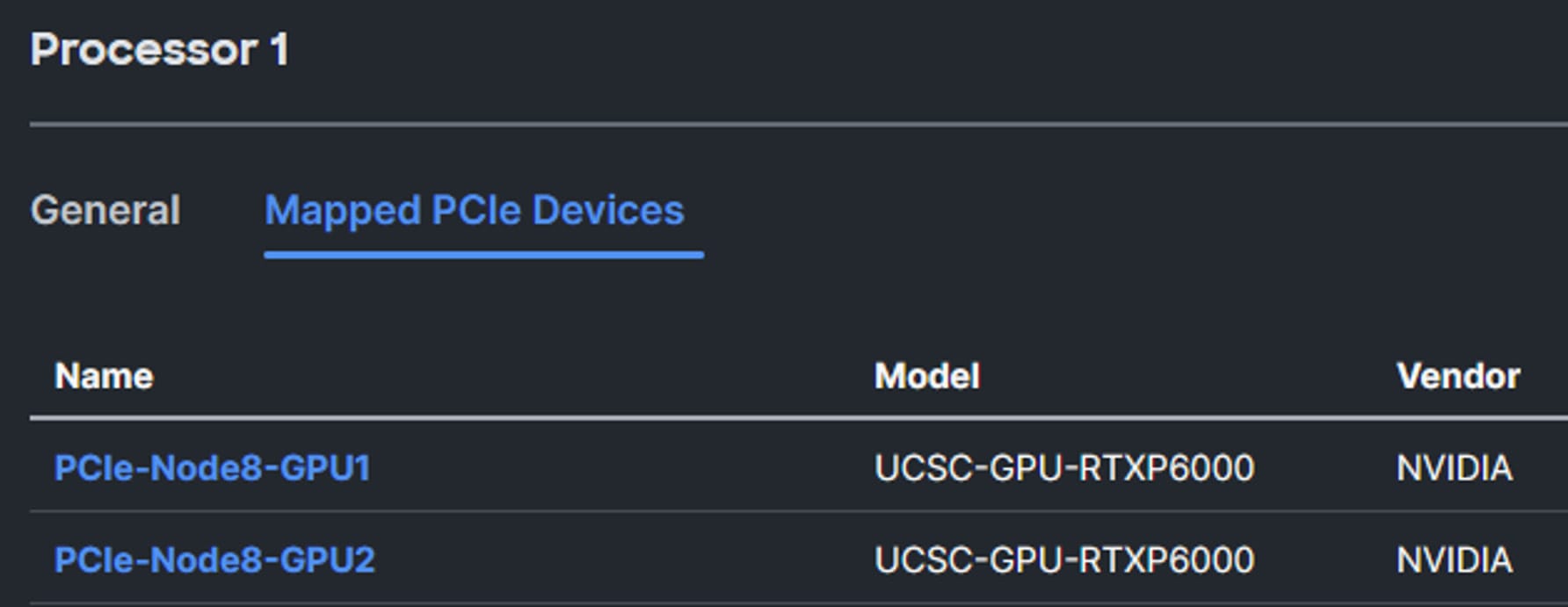
Mapped PCIe Devices view
Alternatively, you can find additional information related to the GPUs and SmartNICs under their respective sections within the server inventory. Figure 11 shows an example of a different host with 4x GPUs mapped from the X580p and 2x network adapters mapped from the XFMs:
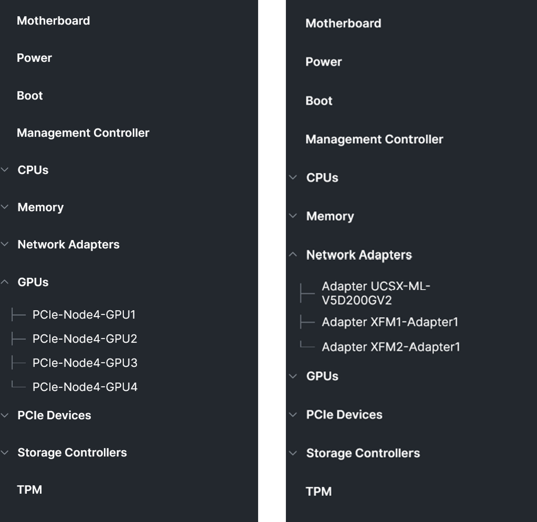
Inventory of mapped PCIe devices example
Once an OS and the appropriate drivers have been installed, additional details can be validated. As shown below, a server has been assigned a PCIe Connectivity Policy allowing the X580p and X9516 to provision 4x NVIDIA H200 NVL GPUs along with 2x NVIDIA ConnectX-7 SmartNICs. A utility called “nvidia-smi” can be leveraged for finding out additional details. For example, to verify the GPU/NIC topology within a host, a systems administrator can use “nvidia-smi topo -m,” which will present information similar to the layout in Figure 12.
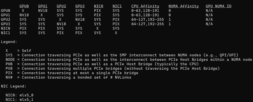
NVIDIA-SMI Topology example
This information is helpful for validating the mapping of the CPUs/GPUs/NICs within the system. Given we have a two-way NVLink Bridge between the GPUs, we can verify that all of the links show as active. To accomplish this, we can run the command “nvidia-smi nvlink –status.” This should result in an output similar to what is being seen in Figure 13.
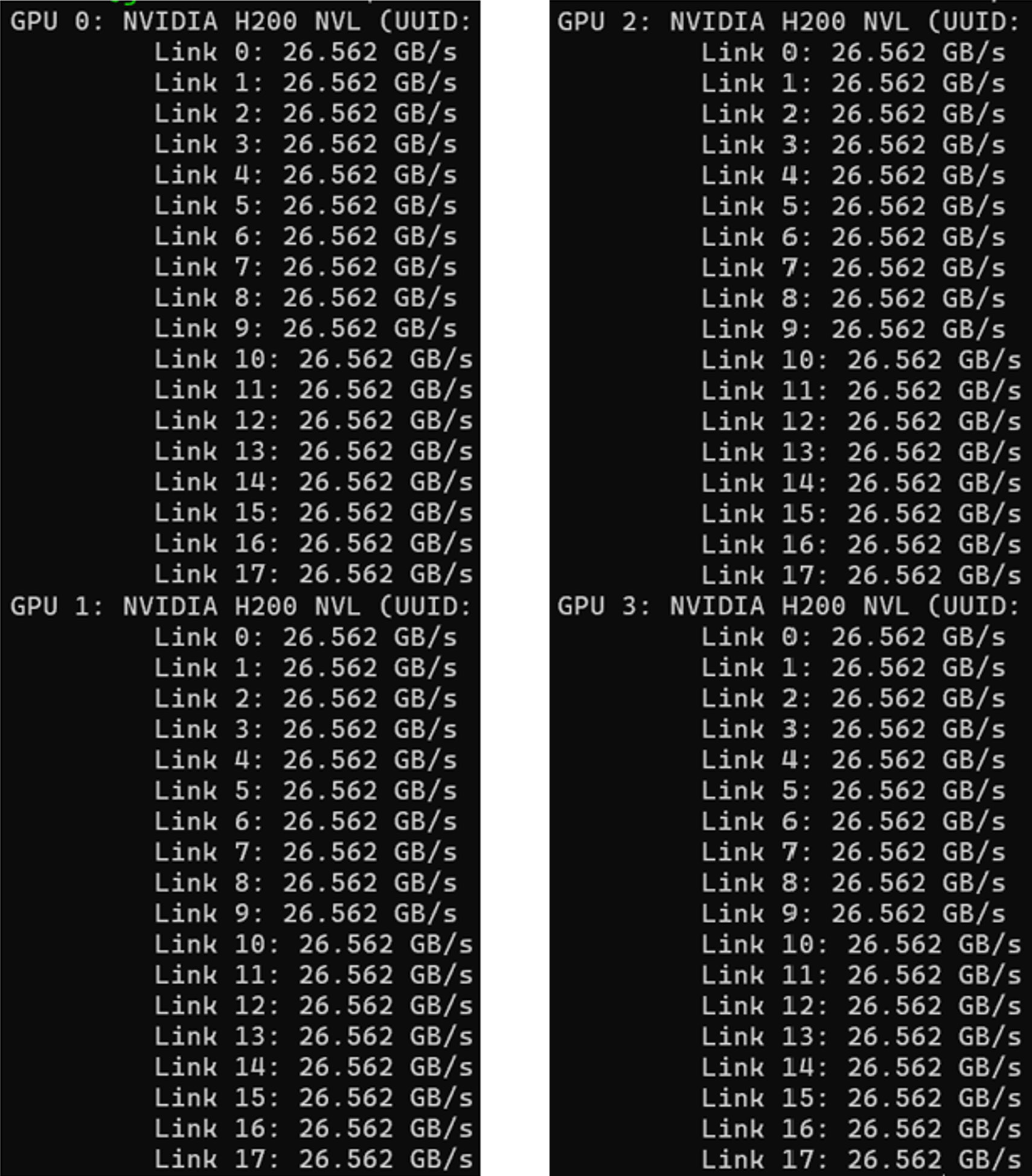
NVIDIA-SMI NVLink Status example
With the enhanced capabilities introduced with the X580p and X9516, we have added the ability to perform firmware updates on the PCIe nodes and XFMs. If a PCIe device (GPU or SmartNIC) is mapped to a server through the PCIe Connectivity Policy, the PCIe device’s firmware may be upgraded through the Intersight server’s firmware update process, not by using the firmware updates to the X580p or X9516. As with any firmware upgrade, follow best practices for system updates, check the Cisco UCS HCL tool and review the Intersight SaaS Help Center for the most up-to-date information regarding Cisco UCS firmware updates.
Starting with the Cisco UCS X9516 X-Fabric, customers will be able to update the XFM firmware through a chassis firmware update feature. This feature allows customers to update not only the XFMs, but also the chassis power supplies if needed. Figure 14 shows several examples of how customers can perform this step.
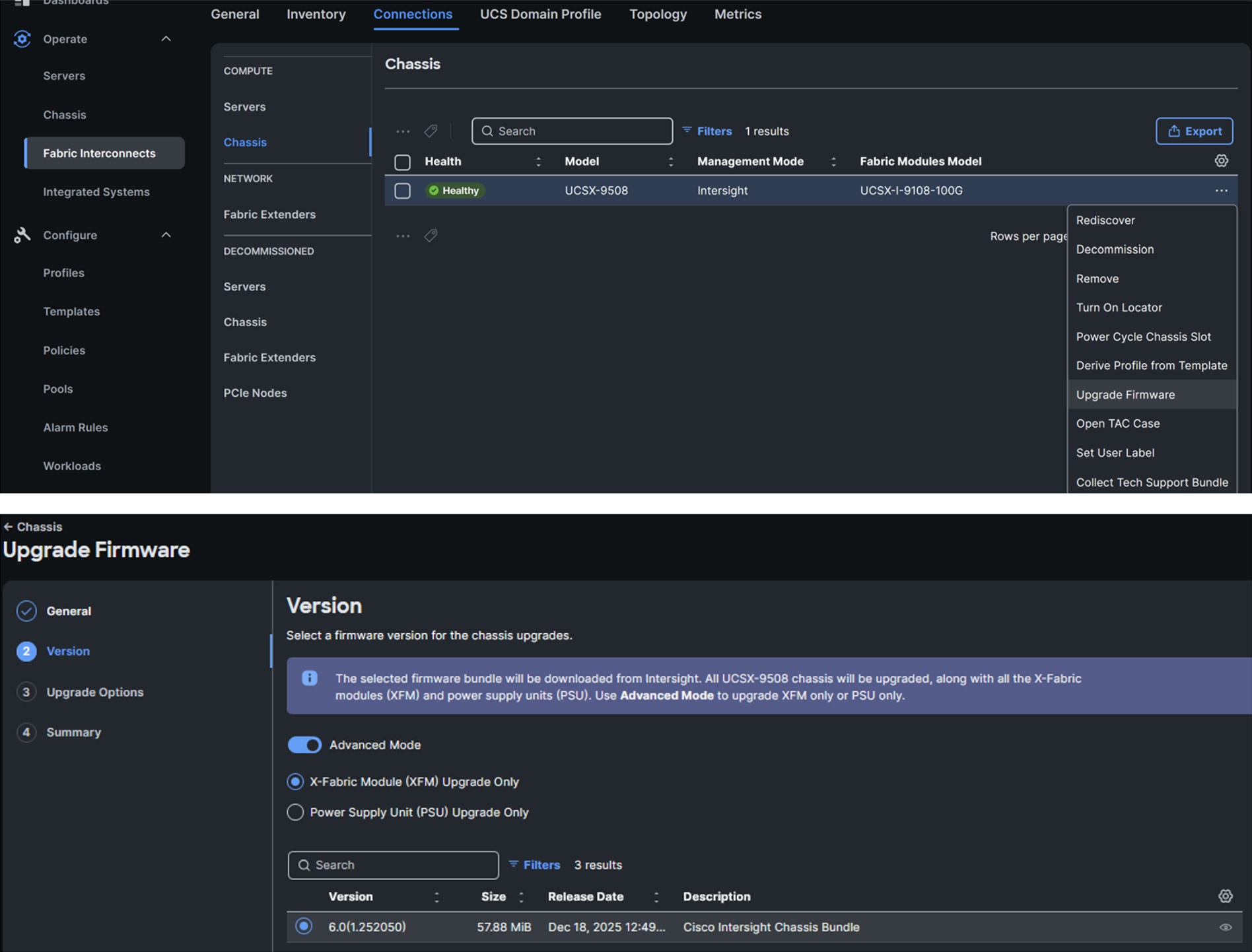
Chassis firmware upgrade example
Moving on to the Cisco UCS X580p PCIe Node, customers will be able to update the PCIe node firmware by first navigating to the chassis inventory, selecting the ellipses next to the PCIe node they wish to update, and selecting “Update Firmware.” (see Figure 15 example). If customers want to update the PCIe devices, these updates will be handled through the server firmware upgrade if they are mapped to the server through the PCIe Connectivity Policy.
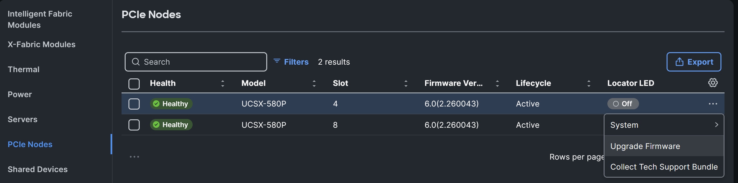
X580p firmware upgrade example
Cisco UCS X-Series adaptive infrastructure
If you’ve made it this far in the document, you may be asking: “This is fantastic! How do I order this amazing solution!” Have no fear, we have a link for that. The Cisco team developed the Cisco UCS X-Series M8 Ordering Guide, which provides the details needed to build a configuration. Please work with your account team and Cisco partner, and they will be able to best assist with making this a reality for your data center. For the latest supported platforms or for additional technical details, please refer to the Cisco UCS X580p PCIe Node spec sheet.
As the team continues to drive innovation with Cisco UCS X-Series, customers can define their computing hardware configuration via policy as their application demands evolve by incorporating the Cisco UCS X580p PCIe Node and Cisco UCS X9516 X-Fabric in their Cisco UCS X-Series environment. With these enhancements, customers can now choose to allocate one, two, or even four GPUs to a server as needed and one or two SmartNICs should the use case require GPUs and connectivity to a backend fabric. These features are delivered through Cisco Intersight (our SaaS-based management platform) to provide flexibility and scalability as workloads evolve.
With this solution, customers can provision their UCS X-Series computing infrastructure configuration via Cisco Intersight which can help with reducing configuration drift as customers deploy systems at scale. This proves we stayed true to one of Bill Shield’s Cisco UCS X-Series introductory blogs title: “UCS X-Series: Unbox the future today.”.