Leveraging Cisco Catalyst Center Wireless Automation for Optimal Network Management White Paper
Available Languages
Bias-Free Language
The documentation set for this product strives to use bias-free language. For the purposes of this documentation set, bias-free is defined as language that does not imply discrimination based on age, disability, gender, racial identity, ethnic identity, sexual orientation, socioeconomic status, and intersectionality. Exceptions may be present in the documentation due to language that is hardcoded in the user interfaces of the product software, language used based on RFP documentation, or language that is used by a referenced third-party product. Learn more about how Cisco is using Inclusive Language.
In the evolving digital landscape, the ability to manage and automate wireless networks effectively is crucial for business continuity. This white paper presents an analysis of the Cisco Catalyst Center Wireless Automation, a solution that enables seamless network management and strengthens security. We explore its various features, discuss its benefits, and provide practical use cases that underscore its transformative potential. Through our insights, we aim to elucidate how Catalyst Center Wireless Automation can help businesses optimize their network management processes and achieve significant efficiency gains.
The content of this white paper is primarily in sync with the most recent version of Catalyst Center Release 2.3.7.6 However, it also points out any discrepancies with version 2.3.5.x or earlier versions of the Cisco DNA Center, which was the previous name for Catalyst Center.
The scope of this document is limited to nonfabric wireless deployments only (both centralized and FlexConnect wireless deployments).
For SDA Wireless Deployments, see this guide.
Catalyst Center is a powerful network controller and management dashboard that allows IT teams to manage and automate their networks.
Catalyst Center enables intent-based networking, a new paradigm for network management. In intent-based networking, the network administrator defines what they want the network to do (the intent), and Catalyst Center translates it into the following to automatically configure devices and services:
● Actionable configuration to fulfill the intent.
● Policies to deploy across the network.
Key features include:
● Design: Allows the creation of network settings and network profiles.
● Policy: Enables the creation of IP and group-based access control policies.
● Provision: Assists in device deployment and application of policies.
● Assurance: Helps in network monitoring and troubleshooting.
● Platform: Allows for integration with other systems through APIs.
Key concepts and terminologies
In the context of Catalyst Center, network settings refer to the configuration parameters that control how the devices operate across your complete network, which include wireless, switching and routing devices. These settings include parameters such as AAA servers, DHCP servers, NTP servers, security settings and so on. These parameters are the nuts and bolts of your network that determine how your network devices communicate with each other and other networks.
In the design phase, you specify these settings according to the needs and requirements of your organization. For example, you can set up different AAA Servers for different sites in your organization to serve the authentication needs for end users.
For wireless users, you can setup all common configuration parameters like SSIDs, RF profiles, ACLs, wireless interfaces and so on.
Some of these settings can be customized and overridden at individual site level, See site level overrides.
A network profile is a template that you can apply to multiple network devices to configure them quickly and easily with the same settings. Instead of manually entering the same settings on each device, you can create a network profile with those settings and then apply the profile to all the devices.
Network profiles not only saves time but also ensures consistency across your network, which can help prevent configuration errors that might cause network problems. In the design phase, you can create these profiles based on the roles and functions of your network devices.
In simpler terms, think of network settings as the individual ingredients of a recipe and the network profile as the recipe itself. Once you've decided what ingredients you need (network settings), you can put together a recipe (network profile) and use it to make the same dish (configure network devices) repeatedly.
Wireless network profile combines all wireless network settings like SSIDs, interfaces, wireless topology type (Fabric, Flex, Central) and so on.
Primary Managed AP Locations: Sites/locations (Buildings/Floors) where access points are located and served by this wireless controller as primary wireless controller that is, all access points on these locations are primed with this wireless controller as Primary wireless controller.
Secondary managed AP locations: Sites/locations (Buildings/Floors) where access points are located and served by this wireless controller as secondary wireless controller that is, all access points on these locations are primed with this wireless controller as Secondary wireless controller.
Anchor managed AP locations: Sites/locations (Buildings/Floors) where access points are located and served by this wireless controller as anchor wireless controller that is, all anchored SSIDs traffic on these Access points is tunneled to this wireless controller.
Overview of wireless automation
Catalyst Center Wireless Automation feature simplifies the process of initiating a wireless network (Day Zero), setting up a new site, and managing the entire wireless network daily (Day n). It provides users with simple and user-friendly options for configuring all wireless settings, such as SSID, RF profile, AP profile interfaces, and more. Catalyst Center then accurately translates this user intent into the correct network intent for Cisco AireOS Wireless Controllers or Cisco Catalyst 9800 Series Wireless Controllers, making it a device-independent intent. The main applications of wireless automation are mostly focused on new wireless network setup and new site deployments. Wireless controller management with existing configuration and existing configuration learning is planned for the roadmap of the year 2024.
Components of catalyst center wireless automation
Following are the key elements of Wireless Automation Intent within the Catalyst Center:
1. Design>Network Settings>Servers: Includes common settings for switching, wireless, and routing, such as AAA servers, DHCP servers, DNS servers, NTP servers, and so on.
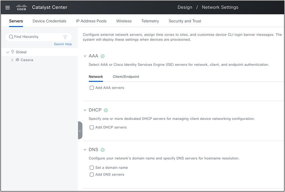
Network Setting: Global Servers
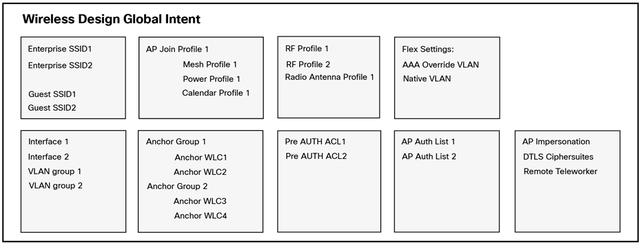
2. Design>Network Settings >Wireless: You can set up the wireless design intent with the following options:
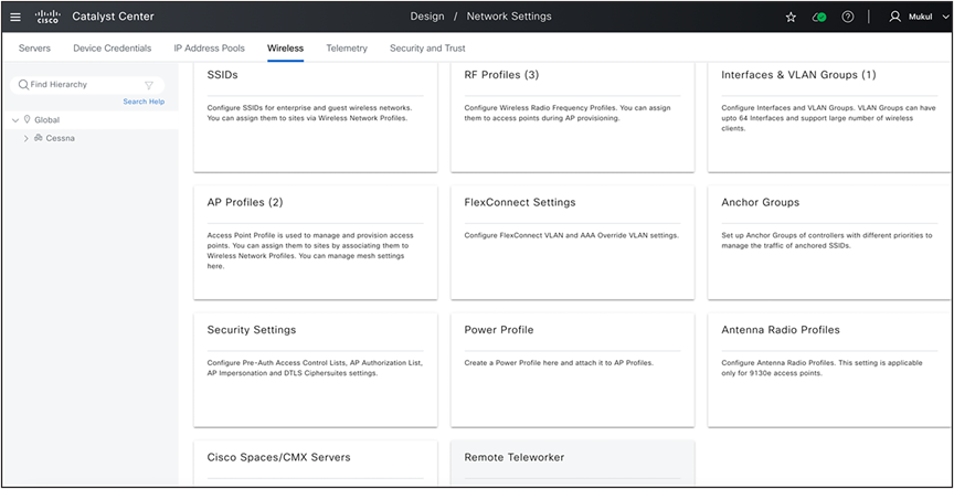
Design: Wireless Global Settings
3. Design>Network Profiles: After defining these design elements, the next step is to map them to the network profile and create additional configuration elements like AP zones, AP groups/flex Groups (For Cisco AireOS Wireless Controllers) and site tags/policy tags (For Cisco Catalyst 9800 Series wireless controllers).
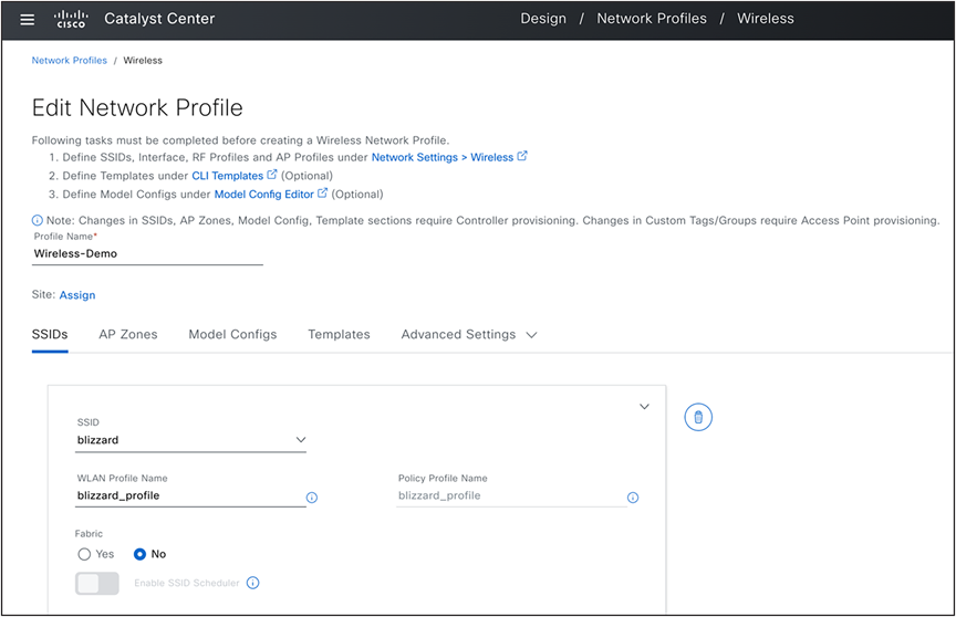
Design: Wireless Network Profile
4. Design>Feature Templates: The next component is the feature templates (model configuration). These advanced settings can enhance the existing intent and can be linked to the network profile. These settings are presented to the user as network intent, mirroring the parameters observable on the device and the Catalyst Center User Interface.
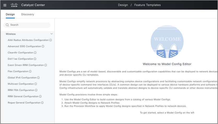
Design: Feature Templates
5. Design>CLI Templates: The last component in the network profile is the CLI templates. Any configuration parameter not supported in network settings, network profiles, or model configurations can be implemented using the CLI templates.
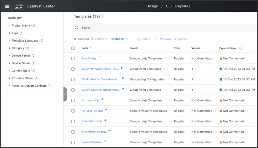
Design: CLI Templates
Setting up catalyst center for wireless automation
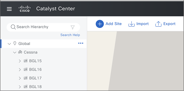
(Design>Network Hierarchy)
Create complete site hierarchy by setting up your campus, building and floor structure. It can also be imported/migrated from prime infrastructure or any other deployment of Catalyst Center.
Step 2: Add/discover wireless controllers
(Provision> Inventory or Tools>Discovery)
Onboard and discover all wireless controllers. If APs have already joined wireless controllers, they are displayed in the inventory. You also have the option to onboard your devices after you have completed the design of your network.
(Systems> Settings >External Services>Authentication and Policy Servers)
(Systems> Settings >External Services>Cisco Spaces/CMX Servers)
You can integrate Cisco Identity Services Engine (ISE) server (Single Policy Administration Node with multiple Policy Service Node) or any other AAA Servers (Multiple), using the appropriate protocol (RADIUS or TACACS). Additionally, you can integrate CMX servers or activate Cisco Spaces to access location services from Catalyst Center.
Step 4: Design Wireless network
Step 4a. Define Network Global Intent
(Design>Network Settings> Servers)
Define all global network settings like AAA servers, DCHP, DNS servers, NTP servers and so on. Note that AAA servers for wireless client end point needs to be setup while creating SSID, but any AAA servers needed for network device authentication need to be setup here.
Step 4b. Review Default Wireless Telemetry Settings
(Design>Network Settings> Telemetry)
This step ensures that all telemetry settings are established for wireless assurance and monitoring functions. By default, Catalyst Center is configured as a trap receiver for SNMP traps, a Syslog servers, and a Netflow collector. You can include any other third-party servers or modify this default setting. You also have the option to disable wireless telemetry. However note that if you choose to do so, you will lose the ability to monitor your wireless network.
Step 4c. Define Wireless Global Intent
(Design>Network Settings> Wireless)
Define all wireless automation configurations you need for your network. Start creating all interface/VLANs, VLAN groups, enterprise SSIDs, Guest SSIDs, AP profiles (which also included mesh, calendar and power profiles), RF profiles, flex settings like native VLAN for all sites, AAA override VLANs, Anchor Groups, and so on.
(Design>Network Settings>Wireless>SSIDs)
You can configure SSIDs with the all necessary basic settings, security settings when you also assign up to 6 AAA servers for authentication and accounting purposes and advanced settings. The default settings and best practices are provided, but you can adjust them as needed.
During SSID creation, you also have an option to associate the Advanced SSID Model Config (feature templates) and choose more parameters like P2P Blocking, DHCP required, and so on. You also have an option to choose the Default Advanced SSID design.
The subsequent step in this process is to create a wireless network profile or add this SSID to an existing wireless network profile. Here, you need to classify this SSID as a Fabric, Centralized, or FlexConnect model and add interface or VLAN group mapping. Additionally, you have the option to designate this SSID as anchored and map it to an anchor group.
(Design>Network Settings>Wireless><Selected Site>)
Catalyst Center permits the modification of network settings at the site level, meaning you can designate global settings such as AAA, DHCP, DNS, NTP at the Global level and have them inherited by all sites. However, you can also modify these settings at any site level, including area, building or floor. By default, all settings are adopted from the parent site. For example, if you change settings at the area level, all buildings within that area inherit these settings, unless you modify the same setting at the building level.
The following is the information message in the user interface.
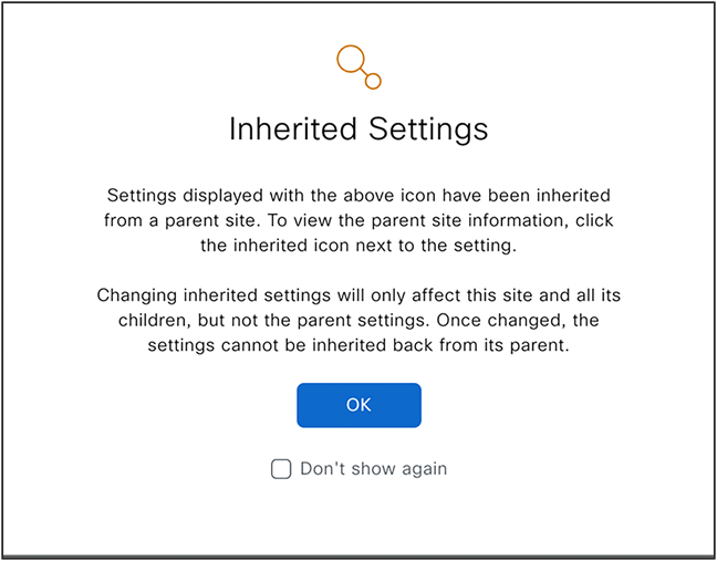
Site Level Overrides
For example, if you establish a global level SSID named 'blizzard' and you need the SSID security settings to be 'Personal' in Building X and 'Dot1X' in Building Y, complete these steps:
First, go to Design>Network Settings>Wireless page and navigate to Building X in the left navigation panel. Select this SSID, click 'EDIT', and modify the security settings to 'Personal'.
Next, repeat the same steps for Building Y, but instead, change the security settings to 'Enterprise (Dot1x)'.
Site Level Overrides are supported for following wireless settings, which means that you can define the same SSID name with different WLAN profile/policy profile name by changing any of these parameters at site level.
Enterprise and Guest SSID
● WLAN/Policy Profile Name
● Layer 2 Security Settings
● Auth Key Management (New in 2.3.7.0)
● WPA3 Encryption
● AAA Servers
● NAS-ID
● Mac Filtering
● Radius Client Profiling
● CCKM
● MPSK
● Protected Management Frame (802.11w)
● AAA Override
● Fast Transition (802.11r)
SSID: WLAN and Policy Profile Name Configuration
1. In Catalyst Center, SSID (WLAN) parameters are split between Design->Network Settings -> Wireless and the Design->Network Profile page.
2. Users can change some SSID parameters at the site level in Network Settings -> Wireless and create a different WLAN profile for the same SSID.
3. Users can also change properties of the same SSID in the Network Profile by providing a different WLAN profile name, such as mapping the same SSID to different VLANs for different sites.
4. This means there are two places where the WLAN profile name is mentioned (Network Settings & Network Profile) for the same SSID but for different sites.
5. Catalyst Center chooses the correct WLAN profile name from these two sources, merges all parameters, and sends this WLAN Profile and Policy Profile to the Wireless LAN Controller.
Until the 2.3.5.5 release, precedence was always given to the Network Settings -> Wireless page for any site-level overrides. However, this caused issues where overrides were done at a higher level (e.g., AREA or Campus level), and multiple network profiles were created at child sites, with different WLAN profile names. Catalyst Center incorrectly chose the WLAN profile name from Network Settings only.
In the 2.3.5.6 and 2.3.7.6 release, the algorithm was changed to consider the WLAN profile name from Network Settings -> Wireless page only when a particular site override is done, and that site is also managed by WLC explicitly.
In upcoming versions (2.3.7.7 onwards) this algorithm is tweaked to always pick correct WLAN and Policy profile name based on most granular name (either from Network Settings or Network profile) for a set of Managed AP Locations.
FlexConnect Settings: AAA Override VLAN
● You can define up to 16 VLAN name and ID Settings per site.
FlexConnect Settings: Native VLAN ID
● You can define Native VLAN for each FlexConnect or branch deployment.
Security Settings: AP Impersonation
Security Settings: Configure DTLS Ciphersuites
Cisco Spaces/CMX Servers
● You can enable location services with different CMX Server for each site.
Remove Site Level Override
If you need to remove override and use the inherited settings, delete the settings at site level (for example if SSID is overridden at any site, click that site in left navigation panel, select that SSID and click Delete) or match the overridden parameter value with its parent. Ensure that the inheritance icon is removed.
Step 4d. Modify/Create Additional Wireless Profiles and Associate to Sites
(Design>Network Profile>SSID)
You can now modify this network profile, which was initially created as part of the SSID creation process. In this network profile, you have the ability to include up to 16 SSIDs and classify them as either Fabric/Non fabric with centralized and FlexConnect traffic switching options. In addition, you can associate a VLAN, a VLAN group, or a local VLAN ID in the case of a FlexConnect deployment.
(Design>Network Profile>AP Zones)
If your deployment necessitates a diverse set of SSIDs or multiple RF profiles per floor, you can utilize the AP zone feature (available from version 2.3.3.0). This feature allows you to use device tags to group Access Points (APs) and assign them to a single AP zone.
An AP zone can be created when there is a need to divide the same floor and create unique sets of SSIDs in each of these zones, or when different RF profiles are required for each zone.
Site Tags/Policy Tags, AP Groups and Flex Groups
(Design>Network Profile>Advanced Settings- Provision Group)
You can specify custom site tags and policy tags for all sites and AP zones, should you prefer to select these names. If these definitions are not provided, Catalyst Center generates these tag names during the Access Point provision operation.
You can establish site tags and policy tags at any level (area, building, or floor) if you are deploying these to Cisco Catalyst 9800 Series Wireless Controllers. For example, you have the option to choose your policy tag at the building level. Catalyst Center applies the same policy tag to all access points situated on every floor of this building. If this is not specified in network profile, Catalyst Center automatically creates a unique policy tag for each floor (even if all floors have the same set of SSIDs). Regarding site tags, Catalyst Center automatically generates a site tag for each building, supporting a maximum of 500 access points in local mode and 300 access points in FlexConnect mode.
For Cisco AireOS Wireless Controllers deployments, you can customize AP groups and flex groups similarly.
Additional Wireless Interfaces
(Design>Network Profile>Advanced Settings- Additional Interface)
If you need to provision multiple wireless interfaces/VLANs on wireless controllers and you're only able to map one interface to an SSID, this section of the wireless network profile can be used to add any additional VLANs.
Based on your wireless network topology (SSIDs and RF profile distribution across your site hierarchy), you may have to create additional network profiles and map to these sites.
The following set of figures provide comprehensive understanding of how all these elements interact.
Wireless Global Intent Elements
This summarises all wireless global elements available in Design->Network Settings->Wireless page.
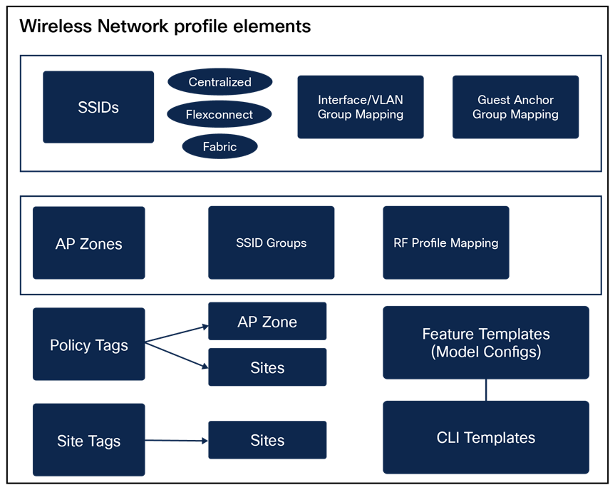
Wireless Network Profile Elements
This summarises all wireless network elements.
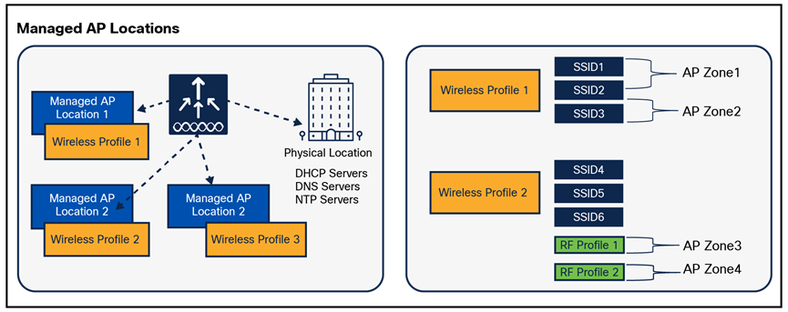
Managed AP Locations Mapping
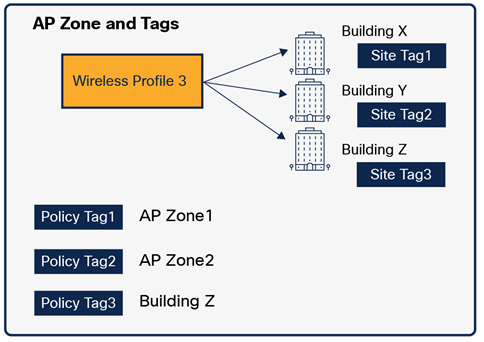
AP Zone and Tags Mapping
In summary WLC is managing multiple managed AP locations, with each location having its network profile which contains all SSIDs, AP zone definition, custom site tag and custom policy definition for all sites where this profile is mapped.
Step 4e. Create Feature Templates (Model Configurations)
(Design>Feature Templates)
(Design>Tools> Model Config Editor) (For version 2.3.5.x and below)
The Feature Templates or Model Config Editor can be used to set advanced wireless configuration parameters. These parameters include advanced SSID parameters, AAA Radius parameters, CleanAir configuration for 2.4-Ghz, 5-Ghz and 6-GHz radio bands, RRM General configuration, Event Driven RRM configuration, RRM FRA configuration, Multicast configuration, Global IPv6, Dot11x, and Advanced Flex parameters.
After these feature templates are created in the design phase (or selected from pre-existing default design instances), they need to be linked to the wireless network profile.
For Advanced SSID Configuration, the option is also available within the network profile to apply these settings to all SSIDs or a subset of SSIDs, as required.
These templates also provide option to override some of these parameter values during wireless controller provision time that is, you can choose to provide a different parameter value for every wireless controller (different from what is configured in design instance), provided you have not locked these parameter, see the following figure on how locked parameter is displayed.
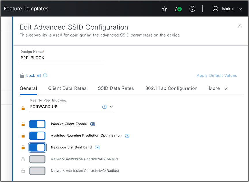
Lock Parameters in Feature Templates
Note that except Advanced SSID configuration feature template all other wireless feature templates are used from a network profile mapped to physical location of this wireless controller so ensure that mapping is done correctly.
Step 4f. Create CLI Templates
(Design>CLI Templates)
(Design>Tools> Template Hub/Editor) (For version 2.3.5.x and below)
Should you need to find a configuration parameter unsupported in previous sections, such as global network settings, wireless network settings, wireless network profiles, or feature templates (model config editor), you can create a raw CLI template and attach it to the network profile. We recommend that you turn on the "Show Design conflicts" button (see the diagram below) and search for any warning icons next to any CLI. It usually indicates that you're attempting to set up a conflicting CLI, which is already natively supported in Catalyst Center. Unless you have a compelling reason (such as not using any intent or feature templates), we recommend that you avoid using these CLI commands.
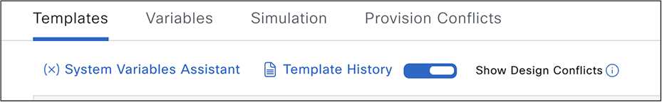
Show Design Conflicts in CLI Templates
Step 4g. Attach Feature and CLI Templates to Wireless Network Profile
(Design>Network Profile>Model Configs)
(Design>Network Profile>Templates)
Final step to finalize your design is to attach all the feature templates and CLI templates. You can apply the Advanced SSID configuration to specific SSIDs, if necessary.
As pointed out in the section, you also have the option to attach the Advanced SSID configuration feature template during the SSID creation/editing workflow too.
"CLI templates are used from the network profile linked to the wireless controller's physical location. However, if you are attaching CLI templates to any SSIDs, the SSID is selected from all network profiles associated with Managed AP Locations."
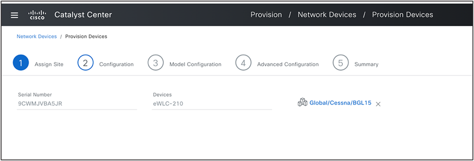
Step 5: Provision wireless controllers and Add Managed AP Locations
(Provision>Inventory><Select wireless controller>>Actions>Provision>Provision Device)
Set the physical location of these wireless controllers and include all sites where the access points, managed by this controller, are located. All global network settings like AAA servers for Network endpoints, DHCP and DNS servers, and NTP servers are determined based on this physical location.
If this controller serves as a backup (N+1) controller for other sites, ensure you assign secondary managed AP locations too. All SSIDs, along with interface/VLAN group mapping and any FlexConnect settings such as AAA Override VLAN and Native VLAN are determined based on these Managed AP Locations.
For example, if a wireless controller is physically situated in a Data Center and manages remote branches in Branch X, Y, Z, then all configurations present in the wireless network profile linked to Branch X,Y,Z are pushed to this wireless controller.
Assign Physical Location to Wireless Controller
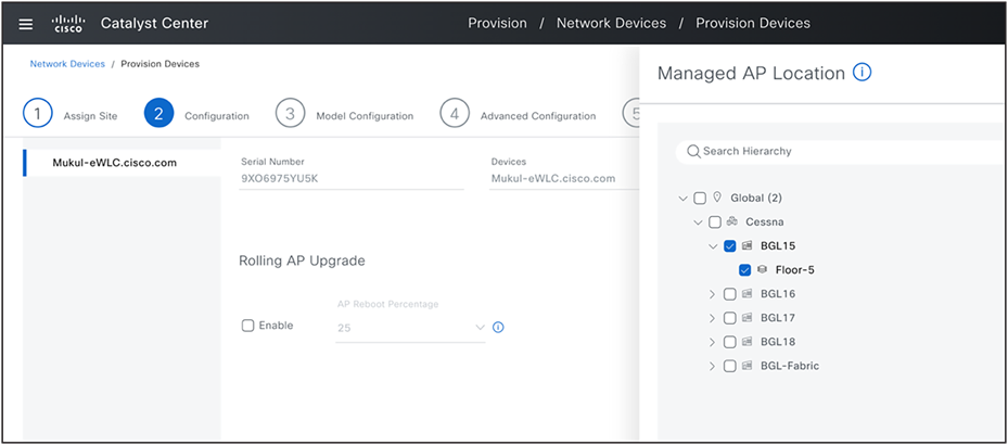
Assign Managed AP Locations
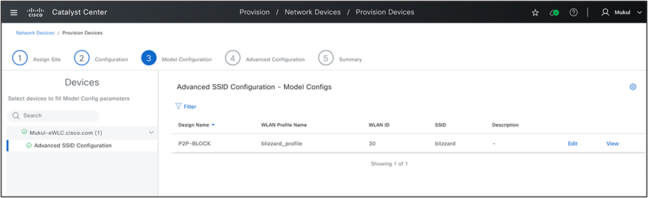
Provision Model Configuration
Wireless controller provision push the following configurations (if configured in network settings and network profile). This can also be verified using the pre provision summary and configuration preview.
● Wireless Interfaces (L2 VLAN and SVI).
● Interface Groups (Cisco AireOS Wireless Controllers) and VLAN Groups (Cisco Catalyst 9800 Series Wireless Controllers).
● AAA Servers for device authentication (configured under Network Settings-AAA> Network end point).
● WLAN Profiles and Policy profiles (Cisco Catalyst 9800 Series Wireless Controllers) based on SSID definition in design.
● Based on site level override, All flavours of WLAN and policy profiles are created.
● SSID Scheduler (Cisco Catalyst 9800 Series Wireless Controllers).
● Authentication (For client authentication) and accounting Servers (Mapped on SSID).
● Pre Auth ACLs (Configured under Network Settings>Wireless>Security Settings page, if it is not configured Catalyst Center automatically generates this ACL based on DNS/DHCP/AAA servers settings and map to guest SSID.
● Country code configuration(based on Physical and Managed AP Locations).
● Anchor configuration on policy profile.
● AP authorization list.
We recommend that you don’t disable the "Visibility and Control of Configuration" setting under the System>Settings page (This setting is available from version 2.3.7.0 onwards and is enabled by default). The following figure shows these settings.
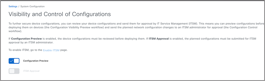
VCR System Setting
Carefully review the Preprovision summary page, which is displayed before you click the Deploy button. Verify that all parameters are set to your desired values. You can modify any default or preset values, as necessary.
For Cisco DNA Center version 2.3.5.x or lower, we recommend that you select the "Generate Configuration Preview" option. Review the generated configuration to ensure that no unintended configurations are present. Specifically, check for any network disruption configurations like SSID flap, radio reset, or per AP configuration CLI. If necessary, schedule this provision to occur during a maintenance window.
Step 6: Onboard new APs using Day 0 PnP (Optional)
(Provision>Plug and Play>Claim)
If you have a new AP and PnP has been set up, you can use the day-zero AP PnP task to claim and provision these access points. This includes assigning the correct site (floor) and RF Profile.
Note that when claiming access points based on the floor assignment, the corresponding primary and secondary wireless controller are selected based on the primary and secondary managed AP location information provided during the wireless controller provision.
It's critical to ascertain that SNMP traps are not deactivated on the wireless controller, as they are used to detect new access points in real-time when they join the wireless controller. This will also trigger a day-zero AP Provision operation once the APs are available in the inventory.
This workflow will also configure AP location parameter on access point with assigned site hierarchy. This later can be alerted to any custom location via AP Configuration workflow.
For more information on using PnP see Catalyst Center documentation listed in References.
Step 7: Provision access points
(Provision>Inventory><Select Access Points>>Actions>Provision>Provision Device)
After APs joined wireless controller, they are displayed in inventory. They can be provisioned by assigning to right floor and RF profile along with AP zone (If AP zones are setup in network profiles).
During AP Provisioning, all AP (Cisco Catalyst 9800 Series Wireless Controllers) tags are generated and allocated to these APs, together with any N+1 related provisions such as primary and secondary wireless controller IPs for access points (given that they are not integrated through PnP). For Cisco AireOS Wireless Controllers, AP groups and flex groups are established and APs are delegated to these groups.
Catalyst Center supports both custom tags and custom AP and Flex groups (set up through the network profile). If these are not present, Catalyst Center automatically generates these tags and groups.
Any modifications to previously provisioned access points, such as modifications of tags or changes in RF profile parameters, are also pushed when the wireless controller is re-provisioned, thus avoiding the need for specific AP provisioning. If there's a change in RF profile or a relocation of sites (floors), AP re-provisioning is necessary.
Access Point Provision applies the following configurations (this can also be verified using pre provision summary and configuration preview).
● Custom RF profile.
● Antenna radio profile for applicable AP models (if configured under Network Settings>Wireless).
● AP join profile along with mesh, power and calendar profile mapping for Cisco Catalyst 9800 Series Wireless Controllers.
◦ If custom AP join profile is not defined, default-ap-join profile is used and you can customize default-ap-join profile also in Network Settings>Wireless page.
● RF tag for Cisco Catalyst 9800 Series Wireless Controllers with RF profile mapping for all radio bands.
● Policy tag for Cisco Catalyst 9800 Series Wireless Controllers (custom or auto generate based on definition in network profile).
● Site tag for Cisco Catalyst 9800 Series Wireless Controllers (custom or auto generate based on definition in network profile).
● RF, site and policy Tag mapping to access points (For Cisco Catalyst 9800 Series Wireless Controllers only).
● AP Group for Cisco AireOS Wireless Controllers (Custom or auto generate based on definition in network profile).
● Flex profile for Cisco Catalyst 9800 Series Wireless Controllers and flex group for Cisco AireOS Wireless Controllers with below configurations if SSID is defined as FlexConnect in network profile.
◦ Flex SSID to Local VLAN Mapping as per network profile.
◦ Native VLAN.
◦ AAA override VLAN.
● Access Point mapping to AP groups and flex groups (For Cisco AireOS Wireless Controllers only).
● AP Mode conversion to FlexConnect if any SSID is defined as FlexConnect in network profile of this floor.
● Primary and Secondary wireless controller IP Priming to access points of secondary managed AP locations are chosen (N+1 Configuration).
After first time provision of wireless controller and access points, any subsequent wireless controller provision always configures all existing provisioned access points unless Skip AP Provision option is chosen.
During the provisioning process of an AP, Catalyst Center assesses the impact on all APs located on the same site (floor) that share the same RF profile, regardless of whether only a few APs are chosen for provisioning. Therefore, it is critical to plan these operation for a time during scheduled maintenance.
Moreover, configurations that necessitate an AP to remain online (such as configurations specific to each AP) might not succeed if the AP is experiencing intermittent connectivity issues or loses connection while provisioning is underway. This could lead to a provisioning failure for all other APs that were selected for the operation.
Wireless automation includes the provisioning of both the wireless controller and the access point, and Provisioning is carried out in two steps when integrating new access points. However, any modifications made on day n during the wireless controller provision is automatically cascaded to all associated APs, eliminating the need for subsequent AP provisioning.
Skip AP Provision can be used during the wireless controller provision process to avoid calculating impact change and applying new design changes to all affected APs, which could considerably reduce the total time required for the wireless controller provision. However, it should be used judiciously. One such use case is adding new managed AP location (New Building or Floor) without recalculating any impact to existing managed AP locations.
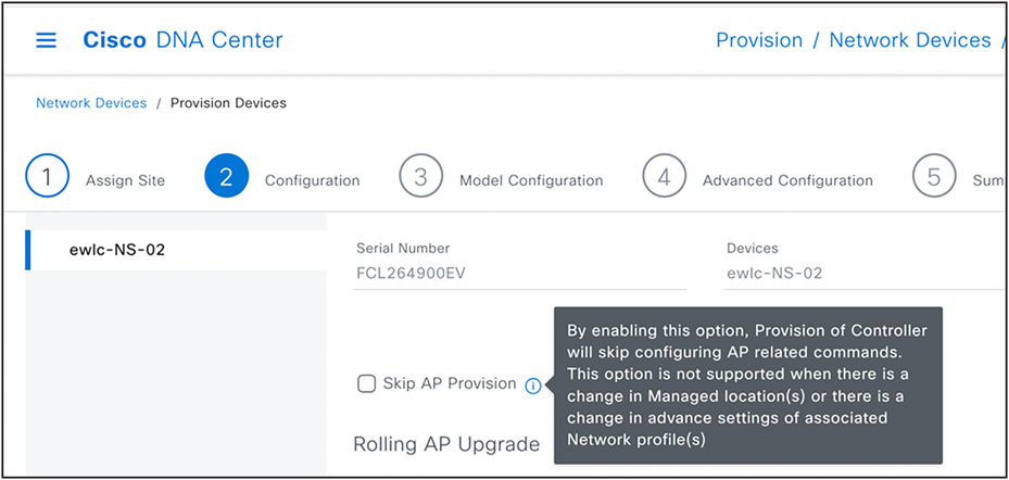
Skip AP provision
1:1 wireless controller HA (AP SSO)
(Provision>Inventory><Select wireless controller>>Actions>Provision>Configure wireless controller HA)
This action can be used to create 1:1 HA Pair (AP SSO) between two wireless controllers.
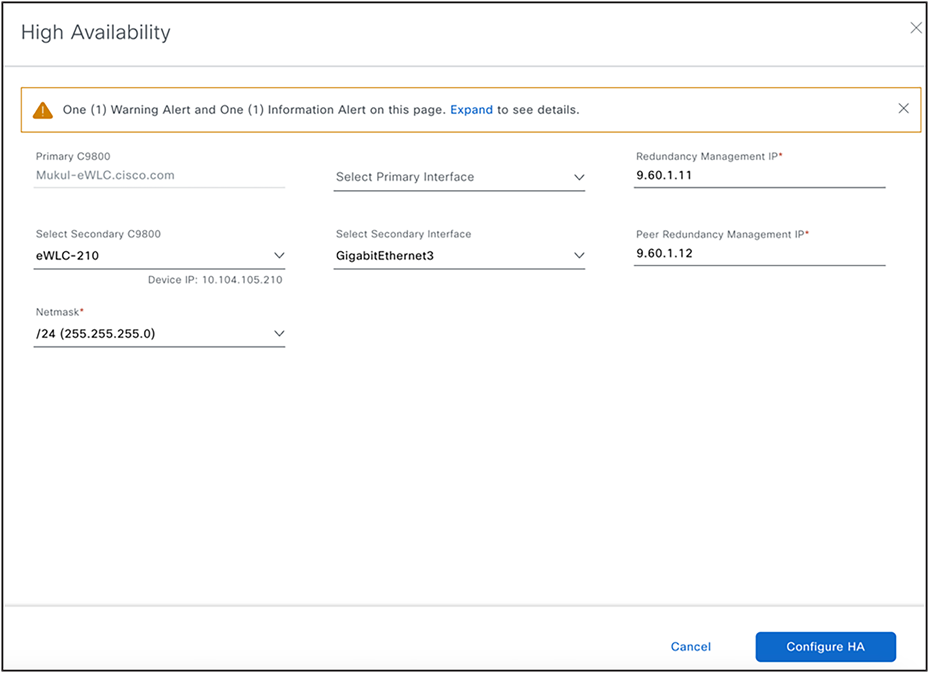
1:1 Wireless Controller HA Configuration
(Provision>Inventory><Select wireless controller>>Actions>Provision>Configure wireless controller Mobility)
This action can be used to configure mobility group, RF group and add mobility peers.
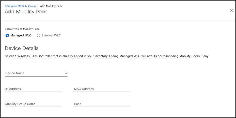
When the workflow is used for the first time, the Catalyst Center will learn all current Mobility Peers (in an existing configuration). The user can then make modifications to add or remove peers. The Catalyst Center will automatically detect associated Mobility Peers of all new peers and display them. Moreover, the system provides the option to include a Wireless Lan Controller (wireless controller) as a Mobility Peer, even if it's not managed through the Catalyst Center (as shown in the screenshot of the External wireless controller below).
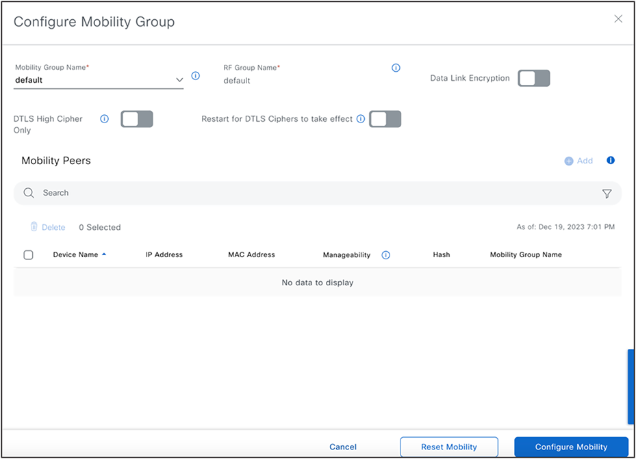
Configure Mobility and Mobility Peers
(Workflows>Configure RLAN)
This workflow is intended for configuring Remote LAN ports on access points and is only supported for Cisco Catalyst 9800 Series Wireless Controllers. Users must select a floor where they intend to set up RLAN ports. The chosen floor should be managed by a Cisco Catalyst 9800 Series Wireless Controllers and have one or more provisioned Access Points. After completing the workflow, re-provision the secondary wireless controller from the inventory page to ensure configurations are pushed. The RLAN is configured to all Access Points on the floor, facilitating client connectivity. Any new access points that are added to this floor in the future will automatically receive this configuration when they are provisioned.
(Provision>Inventory><Select wireless controller>>Actions>Provision>Provision Device>Select Role-Anchor wireless controller)
This process involves setting up an anchor group on the Network Setting> Wireless page, where you can select up to three anchor wireless controllers and associate them with any SSID that you want to anchor traffic to (usually for guest SSIDs). Then, you provision these wireless controllers (chosen in the anchor group) with a role as Anchor. You must select all anchor managed AP locations for which you want these wireless controllers to act as anchors. Catalyst Center configures all SSIDs where the anchor group is mapped in these network profiles and set them up on both the anchor and the corresponding foreign wireless controller (the wireless controller serving as the Active Main wireless controller role with the primary managed location being the same as the anchor managed location). Catalyst Center also creates mobility tunnel between these anchor wireless controllers and corresponding foreign wireless controller.
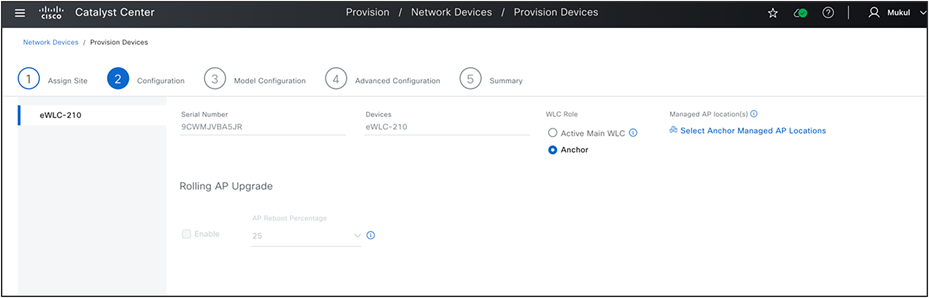
Anchor Wireless Controller Configuration.
(Provision>Inventory><Select wireless controller>>Actions>Provision>Provision Device>Select Secondary Managed AP Locations)
During the wireless controller provision workflow, select the secondary Managed AP Locations, which are the AP locations where this wireless controller serves as a backup wireless controller. Then, whenever Access Point provisioning is carried out on the primary wireless controller, Catalyst Center automatically replicates all tag configurations (AP group/flex group in the case of Cisco AireOS Wireless Controllers) on the secondary (N+1) wireless controller.
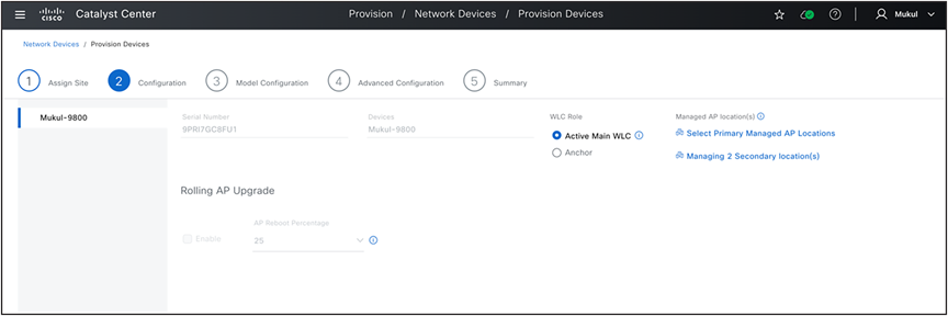
N+1 Wireless Controller Configuration
(Design>Network Settings>Wireless>SSID>SSID Scheduler)
This page can be used by wireless network administrators to set up an SSID scheduler. This scheduler enables or disables any SSIDs at scheduled dates and times. Once created, it can be linked to any SSID within the wireless network profile.
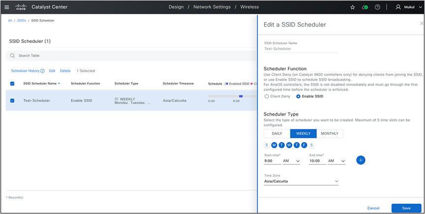
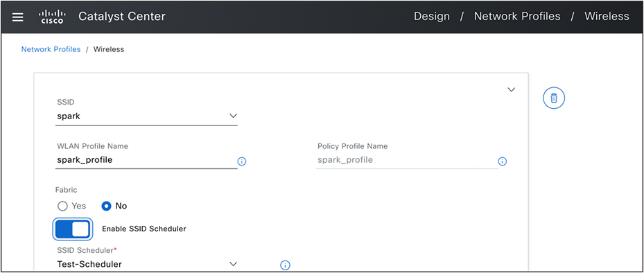
SSID Scheduler and Map to SSID In Network Profile.
(Workflows>Access Point Refresh)
The AP Refresh feature allows you to replace older AP models with newer AP models, using the Access Point Refresh workflow.
Ensure that the old AP is in unreachable state and assigned to a site or if you want to schedule this workflow at later stage, you can continue but when the new AP joins the network, old access points need to be offline (unreachable).
The old AP site must be provisioned as managed AP location for the wireless controller to which the new AP is associated.
The new AP must not be assigned to any site.
You must connect the new AP to a Cisco Wireless Controller. The new AP must either be available in the Catalyst Center Inventory or contact Catalyst Center through Plug and Play (PnP). It must be in Reachable state.
See the user guide in References section for detailed steps on this workflow.
(Workflows>Configure Access Points)
For changing any access point or radio configuration (Per AP configuration setting like AP Admin status, AP Name, AP LED status etc), use Configure Access Point workflow under the Workflows menu.
This workflow can be applied to any access points, regardless of whether they have been provisioned or assigned to a site in Catalyst Center.
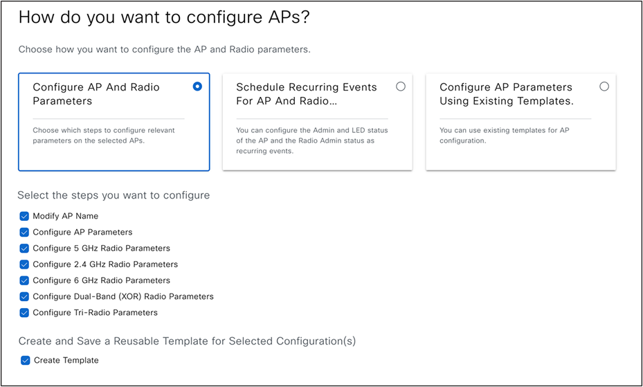
Configure Access Points Workflow Start Page
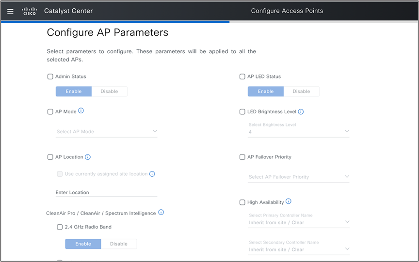
Configure Access Points: AP Parameters
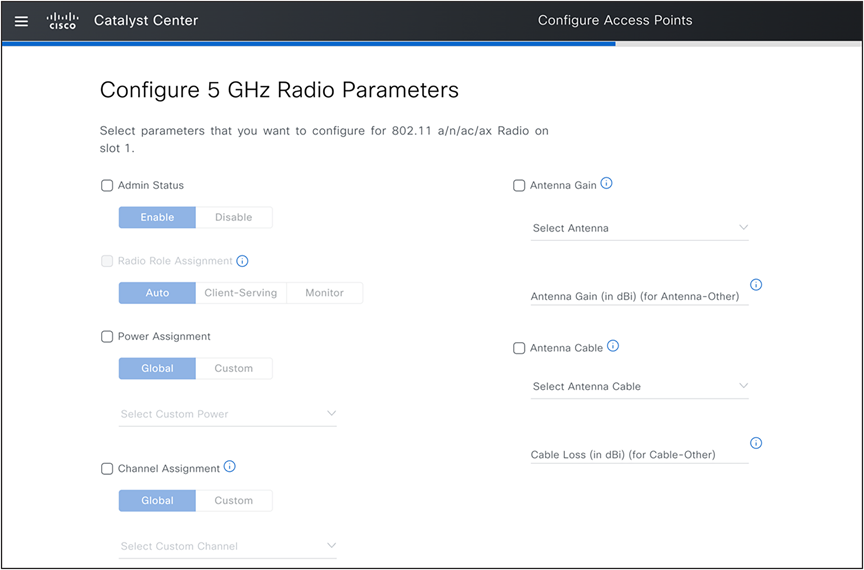
Configure Access Points: Radio Parameters
(Policy>IP and URL Based Access Control)
This workflow allows to associate any IP and the URL-based access control policies (post authentication) on already provisioned SSIDs on any site using wireless controller and AP Provision workflow discussed earlier.
You can create all ACL rules based on the IP addresses or URL and provision the same to any nonfabric SSIDs for both Cisco AireOS Wireless Controllers and Cisco Catalyst 9800 Series Wireless Controllers.
To customize preauthentication ACLs for guest SSID, see Network Settings>Wireless> Security> Pre Auth ACLs.
(Policy>Application QoS>Application Policies)
You can create application policy by categorizing your business applications into various bucket and assign to already provisioned SSIDs on any site with this workflow.
Catalyst center design intent and CLI template
In the previous sections, we covered that any configuration parameters not addressed within the Catalyst Center design intent, such as network settings, wireless network settings, wireless network profile, and feature templates, can be implemented using CLI templates to push the configurations to wireless controller. We recommend that you check for any potential conflicts using the "show design conflicts" option in CLI template editor and confirm that conflicting CLIs are not included in the CLI template.
When CLI templates are used in the Catalyst Center version N, it is advised to review all CLI templates again after upgrading to version N+1. This is to check for any conflicts due to new feature and parameter support in Intent and remove these CLIs, adjusting them into suitable intent screens. If you need assistance with cleaning up the CLI template, contact the Cisco Technical Assistance Center (TAC) team.
To identify any runtime conflicts, you can run a compliance report to detect any discrepancies between out-of-band configurations and the Catalyst Center intent. Without this verification, Catalyst Center may override the out-of-band configurations or configurations pushed with the CLI template unless the CLI template is force pushed with every wireless controller provision operation.
For detailed instructions on modifying Intent based on the CLI template and compliance report, see Wireless Automation MoP document It also provides guidance on how to interpret compliance reports.
Problem Statement: As a network administrator, my task is to make sure that all the access points in conference rooms in new building advertise only SSID named spark.
Assumption here is that the network administrator has already setup the site hierarchy as follows.
Current Site Hierarchy
● Create the new building and all floors.
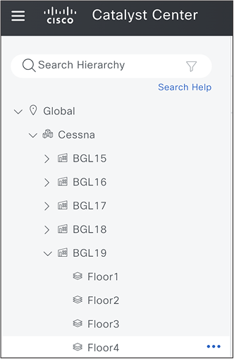
Additional of New Building and Floors
● Edit the network profile and map new building. Now setup AP zones for conference rooms in BGL19, and group the access points in conference rooms with device tag named ‘Conf-Room’.
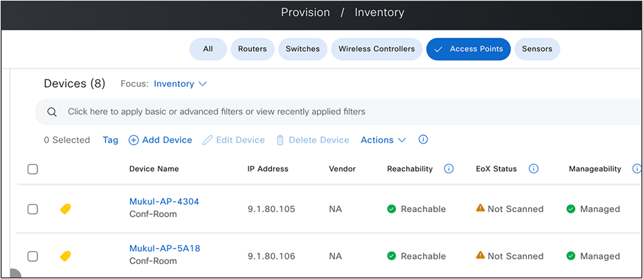
Conf-Room Device Tag Mapping to Access Points
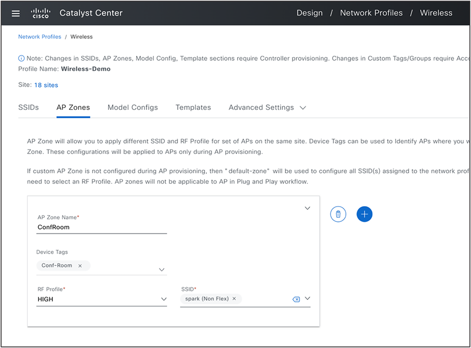
AP Zone Setup in Network Profile
Use case 2: FlexConnect deployment with AAA override and Native VLANs
Problem Statement:
As a network administrator, I need assistance in designing a wireless network in Catalyst Center. The goal is to establish a new wireless FlexConnect branch at the Hyderabad site. This configuration include the implementation of a new set of VLANs supported via AAA override, and the Native VLAN 10 specifically for this branch. Additionally, I want to assign a custom site tag name, 'hyd-central', for this branch, as well as a flex profile name, 'hyd-central-flex-profile'.
● Create a branch site in network hierarchy below.
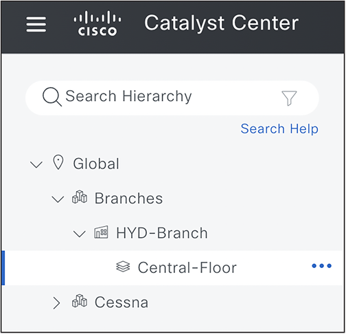
Create New Branch and Floor
● Navigate to Design> Network Settings> Wireless and click FlexConnect Settings. Create a set of AAA Override VLANs by selecting this branch in left navigation panel and up to 16 VLANs, Also configure Native VLAN 10 for this site.
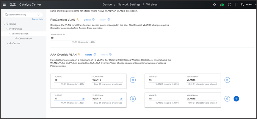
Add FlexConnect Native VLAN and AAA Override VLAN
● If FlexConnect SSIDs for this branch and corresponding network profiles are already setup, assign this new branch to existing profile, If not create SSIDs and network profile and assign to this new branch.
● Navigate to Design>Network Profile >Select Profile> Edit> Advanced Settings> Provision Group> Site Tags and AP Profile> Create Custom Site Tag.
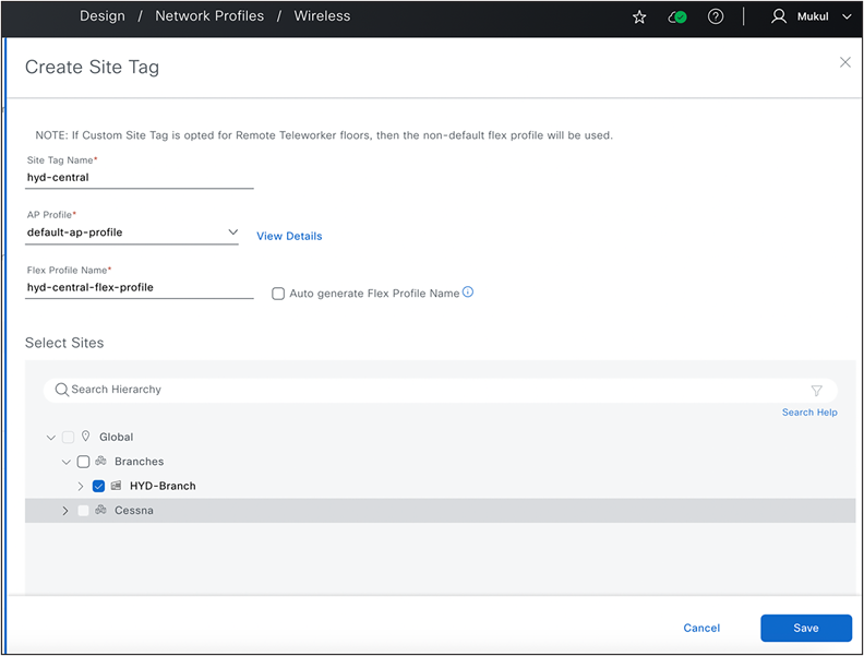
Create Site Tag
Use case 3: Rebalance Access points and onboard new wireless controller
Problem Statement: As a network administrator, I require help in redistributing my access points from an existing wireless controller to a new wireless controller, ensuring minimal network downtime and complete configuration replication on the new wireless controller.
1. The essential preliminary step is to ensure that a N+1 secondary/backup wireless controller is already established and provisioned in the network. If not, set it up, see N+1 HA Configuration section.
2. Relocate the necessary access points from the old wireless controller to the N+1 wireless controller using the access point configuration workflow.
3. Wait for inventory sync to detect this AP movement and ensure APs associated WLC IP is reflecting N+1 wireless controller IP.
4. Provision old wireless controller and delete the corresponding primary managed AP locations*
5. Set up the new wireless controller with the same sites (primary managed AP locations) that were previously removed from the old wireless controller.
6. Move these access points from the N+1 wireless controller to the new wireless controller using the access point configuration workflow.
7. Wait for inventory sync to detect this AP movement and ensure APs associated WLC IP is reflecting new wireless controller IP.
8. Provision all migrated access points to get required tag mapping on new wireless controller.
Cisco prime infrastructure to catalyst center migration
See the guide for comprehensive guidelines for cisco prime infrastructure to catalyst center migration.
Best practices for using catalyst center wireless automation
● Ensure that you go through all the informational icons, warning signs, and any information banners displayed on all pages. This information also indicates if a specific configuration parameter is exclusively supported for certain device families (such as Cisco AireOS Wireless Controllers vs Cisco Catalyst 9800 Series Wireless Controllers) or specific device software versions.
● It is recommended to review the 'What’s New' banner on the Network Settings -> Wireless page to familiarize yourself with all the new parameters and default values introduced in the latest Catalyst Center release.
● We recommend that you link sites at a higher level in the site hierarchy, such as the area/Campus node, when associating them to a network profile and selecting managed AP locations during wireless controller provision. This approach facilitate the automatic inheritance of all child sites or new buildings in the future.
● If you're using both site-level overrides and network profile overrides (the same SSID with varying network profile properties for different sites), Catalyst Center selects the WLAN/Policy profile name from the wireless network profile. However, if any site-level override is applied and the site is part of a WLC Managed AP Location, the WLAN/Policy profile name will be taken from the wireless network settings page (site-level override).
◦ However, this behavior will be modified in the upcoming Catalyst Center version to accommodate all possible combinations of site-level overrides and network profile overrides, ensuring that customers transitioning from previous releases will continue to have the same experience as before.
● For any modifications to the AP zone you must provision wireless controller before AP provisioning, So we recommend that you establish all SSIDs and AP zones in advance to avoid additional wireless controller provisioning operations.
● Changes to SSID to managed site mapping, such as which SSID is broadcasted on which AP location, requires wireless controller provisioning.
● After upgrading to a new release of the Catalyst Center, ensure you review all design pages and check the default values of all new features and configuration parameters.
● Review the pre-provision summary during wireless controller and AP Provision operations.
● Generate a configuration preview before every provisioning operation, especially if you're using version 2.3.5.x or earlier.
● Ensure the 'Visibility and Control of Configuration' setting is enabled in the system settings if you are using 2.3.7.x and above versions.
● Review compliance reports before initiating any provisioning operation and understand that all reported violations will be overridden in the next provisioning operation. If you need to keep device values, adjust the intent and network profile as necessary.
● Avoid configuring any conflicting CLIs in the CLI template. Use the "Show design conflicts" toggle to check for any such CLIs. If you're using version 2.3.5.x or earlier, contact the Cisco TAC team for help with creating and using CLI templates.
This white paper provides an in-depth analysis of Catalyst Center Wireless Automation, a solution designed to simplify and enhance wireless network management and security. It provides a step-by-step guide on setting up and using the system, covering everything from design and policy to provisioning. It also details how to adjust settings for different sites and Access Points, and how to create and implement network profiles. It includes detailed instructions on using Wireless Automation features, setting up the Catalyst Center, and performing day-to-day operations. It provides best practices to optimize the use of the Catalyst Center Wireless Automation. This comprehensive guide demonstrates the potential of Catalyst Center Wireless Automation to streamline network management, bolster security, and achieve significant efficiency gains.
Frequently Asked Questions (FAQs)

● As mentioned in best practices we recommend that you look for any compliance violations reported during any provision workflow as these settings will get overwritten by catalyst center, if not we recommend that you adjust these values in network settings and wireless network profile to align with any out-of-band changes.
● Catalyst Center will override any out-of-band configurations made directly on the device if they conflict with values configured under network settings and network profiles. If you are using a CLI template, enable the 'Show design conflicts' toggle button and pay attention to any conflicting CLIs, as Catalyst Center intent may overwrite them.
● All other non-conflicting configurations will remain unchanged on the wireless controller and can be verified using the configuration preview.
● Controller Certificates
● SNMP Trap Server Definitions
● Syslog Server Definitions
● Application Visibility
● Wireless Service Assurance (WSA)
● Wireless Telemetry Subscriptions
● DTLS Ciphersuite
● AP Impersonation
1. Catalyst Center User Guide (2.3.7.x)
2. Catalyst Center User Guide (2.3.5.x)
3. Cisco Validated Design for Wireless Automation
4. Cisco Prime Infrastructure to Catalyst Center Migration
Author
Mukul Bhanawat, Wireless automation team