Cisco N9000 Cloud RA with NVIDIA GB300 NVL72
Available Languages
Bias-Free Language
The documentation set for this product strives to use bias-free language. For the purposes of this documentation set, bias-free is defined as language that does not imply discrimination based on age, disability, gender, racial identity, ethnic identity, sexual orientation, socioeconomic status, and intersectionality. Exceptions may be present in the documentation due to language that is hardcoded in the user interfaces of the product software, language used based on RFP documentation, or language that is used by a referenced third-party product. Learn more about how Cisco is using Inclusive Language.
Featuring Networking Reference Architecture of NVIDIA GB300 NVL72 with Cisco N9000
The Cisco NCP compliant Cloud Reference Architecture (RA) is designed to be deployed with a high GPU scale at large Cloud Service Providers (CSPs) and high-performance Super Computing Centers (SCCs) in order to solve the most computationally intensive problems without affecting ease of provisioning and operations. The overall design supports multitenancy in order to maximize the use of deployed hardware and, if required, can be scaled to 73728 GPUs. The key technologies used in this RA include:
● NVIDIA GB300 paired with ®-8 SuperNICs, Bluefield®-3 DPUs.
● Cisco N9000® Series Switches combined with on-premises Cisco Nexus Dashboard networking controller.
● Cisco Optics and cables.
● Cisco provisioning, observability and security frameworks.
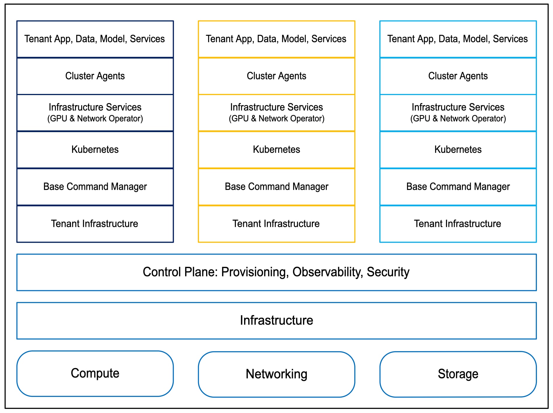
Logical View of Cisco Cloud Reference Architecture
Support for the overall solution is provided by Cisco in collaboration with its partners. All customer cases are front end by Cisco and after triage, where applicable, routed to appropriate partner support on the backend driving case resolution.
GB300 NVL72 Rack
This RA uses NVIDIA-Certified® GB300 NVL72 racks where each rack consists of 18 compute trays and 9 NVL5 switch trays. Each compute tray is in 2-4-5-800 (C-G-N-B) configuration where C-G-N-B naming convention is defined as:
● C: Number of CPUs in the node.
● G: Number of GPUs in the node.
● N: Number of network adapters (NICs), categorized into:
◦ North/South: Communication between nodes and external systems.
◦ East/West: Communication within the cluster.
● B: Average network bandwidth per GPU in Gigabits per second (GbE).
Within each compute tray, there are 4x NVIDIA B300 GPUs paired with 2x Grace CPUs – one Grace CPU and two B300 GPUs together form a GB300 SuperChip. Each NVL5 switch tray consists of 2 NVSwitch ASICs per tray connecting to every GPU within the rack using NVL5 links. The 72 GPUs via the 18 NVSwitch ASICs together form a single coherent memory domain using the scale up network within the rack. Across the racks, GPU connectivity from every compute tray to other servers is via the use of 4x integrated NVIDIA ConnectX®-8 SuperNICs for East-West scale out traffic and via 1x NVIDIA BlueField®-3 B3240 DPU NICs for North-South traffic. Supermicro SRS-GB300-NVL72 is an NVIDIA-Certified® GB300 NVL72 rack supported in this RA.
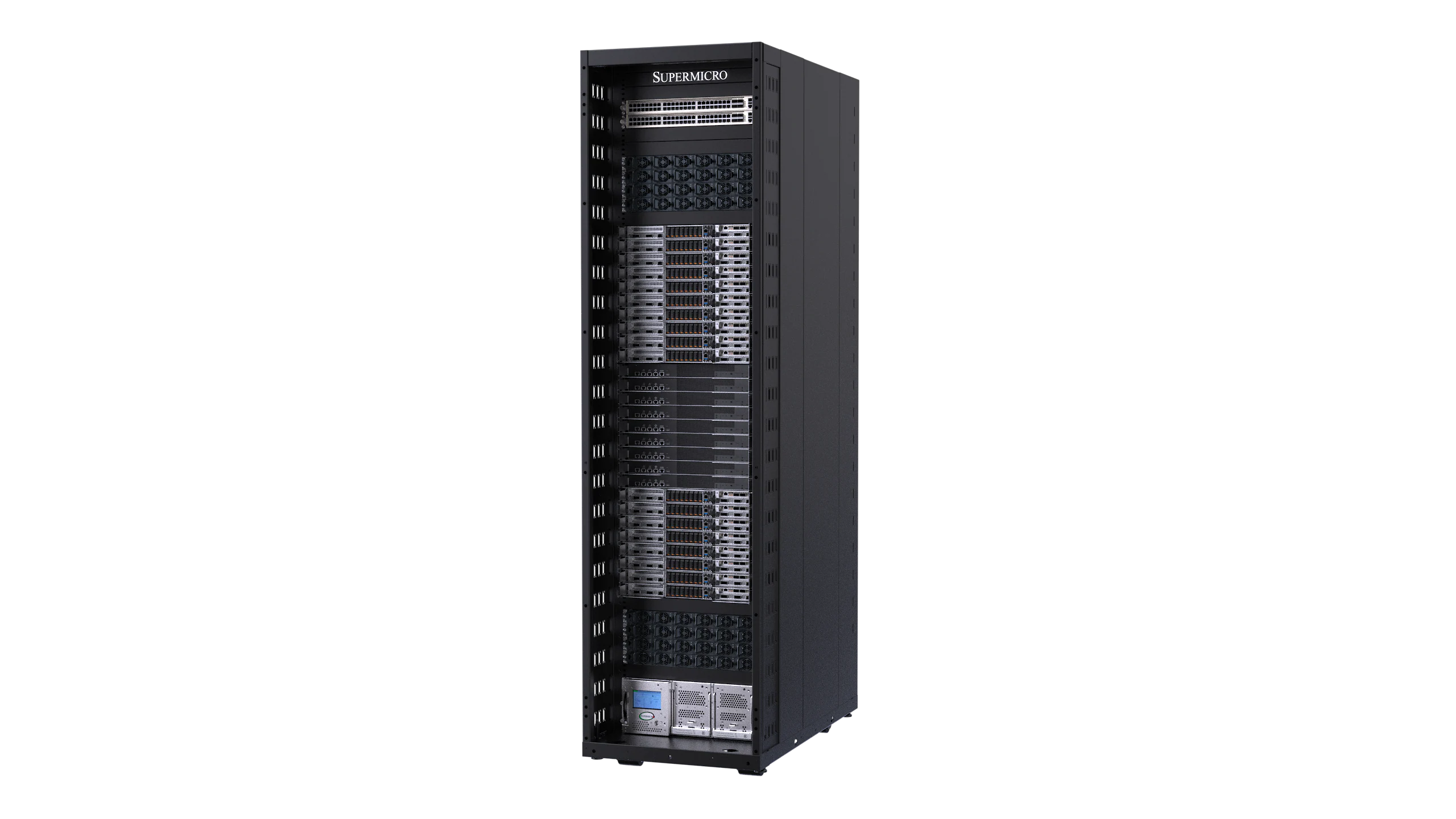
Supermicro SRS-GB300-NVL72 Rack
Cisco N9364E-SG2-O
The Cisco N9364E-SG2-O is a Cisco Silicon One™ Ethernet Switch ASIC-based 2RU switch supporting 64 800G OSFP modules allowing 64 800GE or 128 400GE ports. This switch will be used in both leaf and spine role.

Cisco N9364E-SG2-O switch
Cisco N9164E-NS4-O
The Cisco N9164E-NS4-O is a NVIDIA Spectrum™-4 Ethernet Switch ASIC-based 2RU switch supporting 64 800G OSFP modules allowing 64 800GE or 128 400GE ports. This switch can be used in both leaf and spine role in East-West compute network, as an alternative to Cisco N9364E-SG2-O, for NCP compliance.
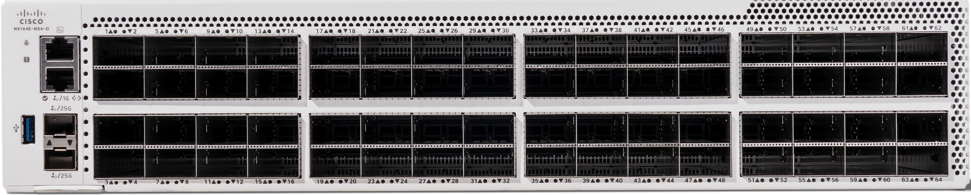
Cisco N9164E-NS4-O switch
Cisco N9332D-GX2B
The Cisco N9332D-GX2B switch provides 32 400G QSFP-DD ports with 10/25/50/100/200-Gbps breakout support in 1RU form-factor. This switch will be used in storage leaf and high-speed management leaf roles.

Cisco N9K-C9332D-GX2B switch
Cisco N9336C-SE1
The Cisco N9336C-SE1 switch provides 36 40/100-Gbps QSFP28 ports in 1RU form-factor. This switch will be used in high-speed OOB management leaf role connecting to the compute rack ToR switch uplinks.

Cisco N93936C-SE1 switch
Cisco N9396T12C-SE1
The Cisco N9396T12C-SE1 switch provides 96 100-Mbps or 1/10-Gbps 10GBASE-T ports and 12 1/10/25/40/100-Gbps QSFP28 ports in 2RU form-factor. This switch will be used in a low-speed OOB management leaf role.

Cisco N9396T12C-SE1 switch
Cisco N93108TC-FX3 switch
The Cisco N93108TC-FX3 switch provides 48 100-Mbps or 1/10-Gbps 10GBASE-T ports and six 1/10/25/40/100-Gbps QSFP28 ports in 1RU form-factor. This switch will be used in a low-speed management leaf role where fan out to spine switches is less than 6.

Cisco N9K-93108TC-FX3 switch
Cisco UCS C225 M8 Rack Server
The Cisco UCS C225 M8 Rack Server is a 1RU general purpose server that can be used in many roles, such as application server, management and support nodes, control nodes for Kubernetes (K8s) and Slurm. Within this RA, these servers are also used to run the VAST Storage solution as described in the “High-Performance Storage” section, below.

Cisco UCS C225 M8 Rack Server
The following Cisco Optics and Cables as shown in Table 1 are being used on different devices in the solution.
Table 1. Supported List of Cisco Optics and Cables on different devices
| Device |
Optics and Cables |
| B3240 |
QSFP-400G-DR4 with CB-M12-M12-SMF cable |
| B3220L |
QSFP-200G-SR4 with CB-M12-M12-MMF cable |
| ConnectX-8 |
OSFPR-800G-DR8 with dual CB-M12-M12-SMF cable |
| N9364E-SG2-O N9164E-NS4-O |
OSFP-800G-DR8 with dual CB-M12-M12-SMF cable |
| N9K-C9332D-GX2B |
QDD-400G-DR4 with CB-M12-M12-SMF cable QDD-400G-SR8-S with CB-M16-M12-MMF cable QDD-2Q200-CU3M passive copper cable QSFP-200G-SR4 with CB-M12-M12-MMF cable |
| N9336C-SE1 |
QSFP-100G-DR-S with CB-LC-LC-SMF, CB-M12-4LC-SMF cable |
| N9K-93216TC-FX2 N9396T12C-SE1 N9K-93108TC-FX3 |
QSFP-100G-DR-S with CB-LC-LC-SMF, CB-M12-4LC-SMF cable CAT5E cable CAT6A cable |
Overview
Overall, the networking topology is split into three separate fabrics:
● East-West Compute Network.
● Converged North-South Storage and Management Network
● Out-of-Band (OOB) Management Network.
East-West compute network
The compute network is meant for collective communications between the GPUs while solving a scientific problem or executing AI training. Customers looking to scale up to a maximum of 4608 GPUs, can deploy the compute network in a two-tier topology with the use of 256 N9164E-NS4-O leaf switches and 72 N9164E-NS4-O spine switches, as shown in the following section. Alternatively, N9364E-SG2-O switches can also be used without NCP compliance. Customer interested to incrementally scale beyond 64 racks (4608 GPUs) should deploy the compute network with a three-tier topology from the beginning. Both the two-tier and three-tier use dual-plane topology where every E-W ConnectX-8 800G NIC (in 2 x 400G mode) is connected to two separate identical planes of switches for avoiding single point of failure. Traffic is optimally load-balanced over both the planes with global awareness instead of using traditional L2/L3 bonds like LAG that use static hash-based traffic distribution. The two globally aware load-balancing scheme that could be used are: (a) Software based Plane Load Balancing (SWPLB) managed by NCCL together with the use of Spectrum-X plugin; (b) Hardware based Plane Load Balancing (HWPLB) managed by ConnectX-8 firmware with Spectrum-X enabled.
Two-tier East-West compute network
The two-tier topology can be incrementally deployed in units of a Scalable Unit (SU) where each SU consists of 2 GB300 racks for a total of 144 GPUs. As shown in Figure 10, 11, 12, within both identical plane 1 and 2, the leaf switches are grouped into four Rail groups 1, 2, 3, and 4 deploying an SU in a rail-optimized manner. The number of leaf switches in each group can be incrementally increased up to a maximum of 32 leaf switches per group. For example, as shown in Figure 11, when Rack#63-64 (SU32) is added, leaf switches L32, L64, L96, L128 are added in Rail group 1, 2, 3, 4 respectively. All GPUs within an SU, are one hop away from each other. However, GPUs across SUs will have to communicate through the spine switches. This approach of grouping rails and rail-optimization per SU makes it efficient in allocating resources in a multi-tenant environment. It avoids one tenant's excessive resource usage from degrading another's performance and ensures that all tenants benefit from shared, yet isolated, infrastructure for large-scale AI training workloads.
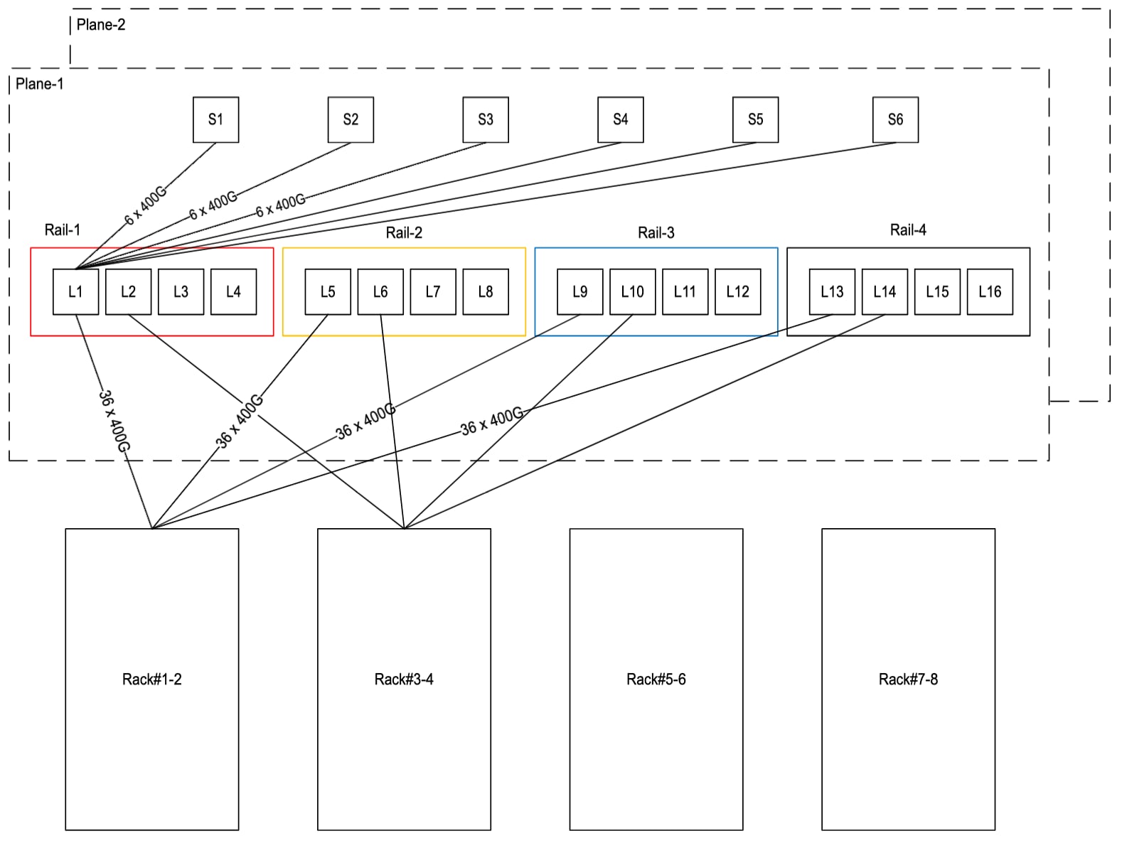
East-West two-tier Compute Network for 8 GB300 racks (576 GPUs)
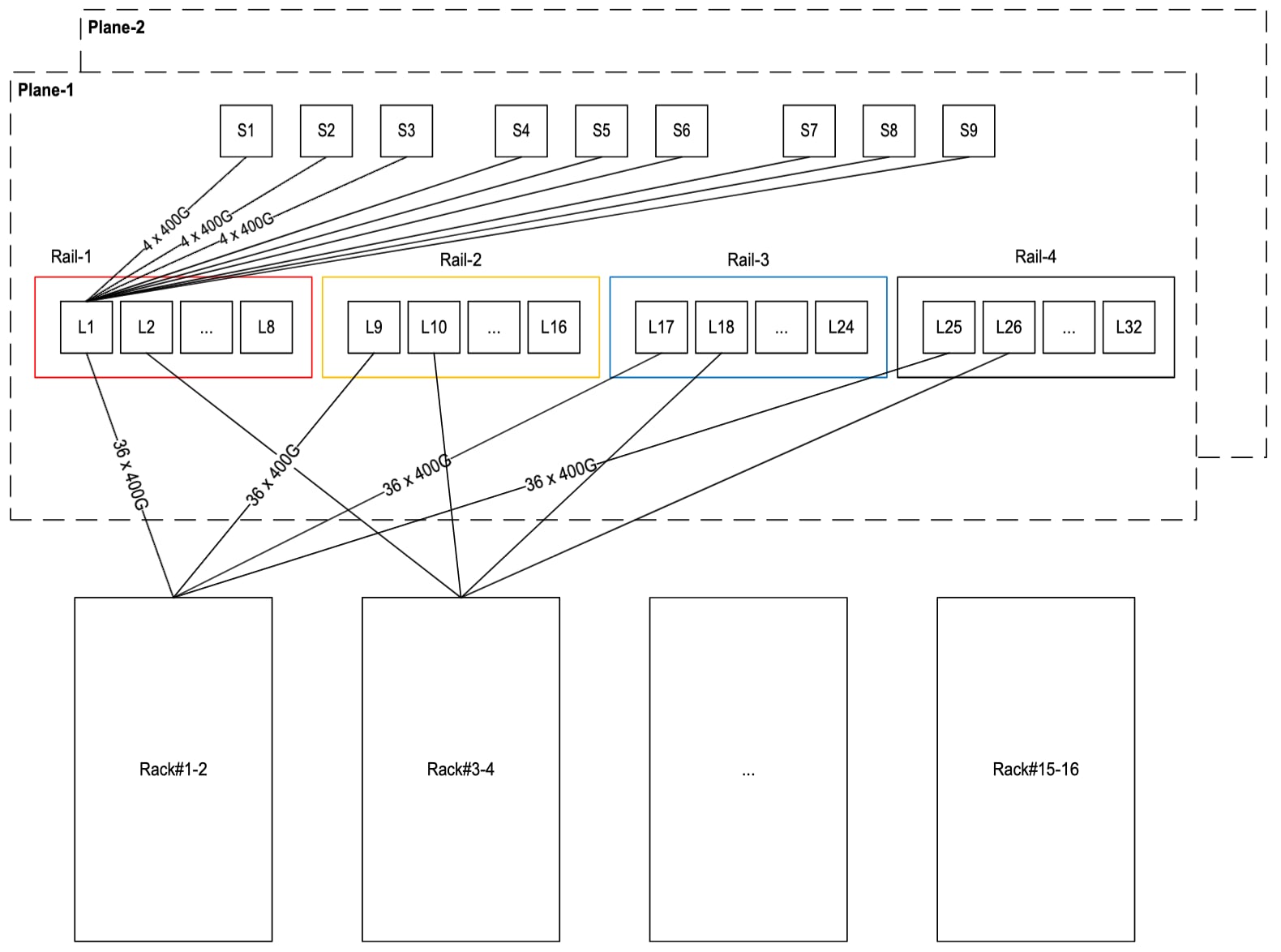
East-West two-tier Compute Network for 16 GB300 racks (1152 GPUs)
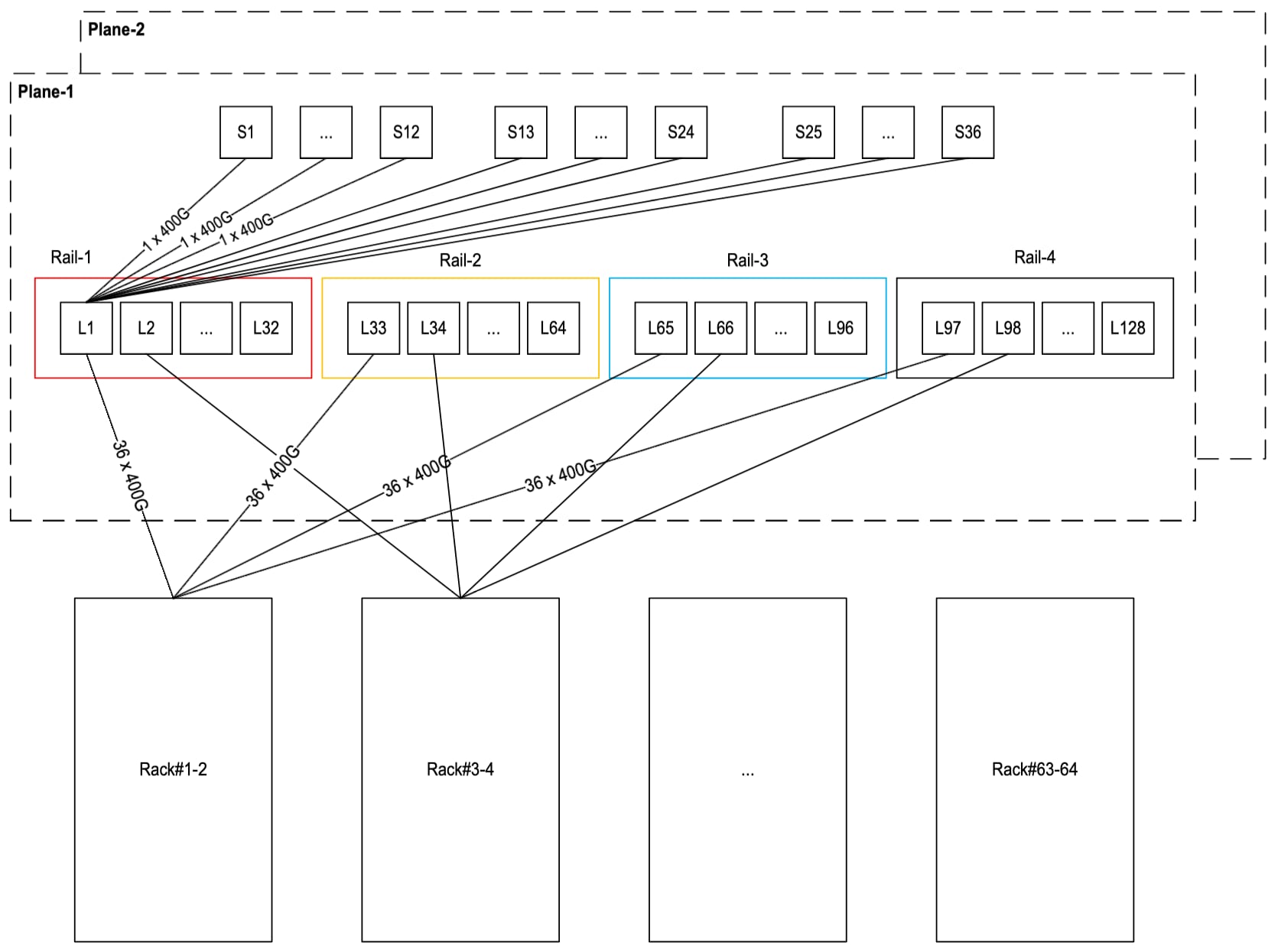
East-West two-tier Compute Network for 64 GB300 racks (4608 GPUs)
The number of switches, transceivers, and cables required to build the two-tier compute network of different scale ranging from 2 racks (144 GPUs) to 64 racks (4608 GPUs) is captured in Table 2.
Table 2. Two-Tier East-West Compute Network Switch, Transceivers, and Cable counts
| Compute counts |
Switch counts |
Transceiver counts |
Cable counts |
||||||||
| Racks |
Nodes |
GPUs |
SUs |
Leaf |
Spine |
SuperSpine |
Node to Leaf |
Switch to Switch (800G) |
Node to Leaf |
Switch to Switch |
|
| Node |
Leaf |
||||||||||
| 2 |
36 |
144 |
1 |
8 |
4 |
0 |
144 |
144 |
288 |
288 |
288 |
| 4 |
72 |
288 |
2 |
16 |
6 |
0 |
288 |
288 |
576 |
576 |
576 |
| 8 |
144 |
576 |
4 |
32 |
12 |
0 |
576 |
576 |
1152 |
1152 |
1152 |
| 16 |
288 |
1152 |
8 |
64 |
18 |
0 |
1152 |
1152 |
2304 |
2304 |
2304 |
| 32 |
576 |
2304 |
16 |
128 |
36 |
0 |
2304 |
2304 |
4608 |
4608 |
4608 |
| 64 |
1152 |
4608 |
32 |
256 |
72 |
0 |
4608 |
4608 |
9216 |
9216 |
9216 |
Three-tier East-West compute network
As shown in Figures 12 and 13, a three-tier compute network is built in a modular way consisting of an SU-group of eight Scalable Units (SUs), where each SU consists of 2 GB300 racks, for a total of 144 GPUs in an SU, and 16 racks or 1152 GPUs in an SU-group. This allows incrementally deploying in units of SU-group of 16 racks or 1152 GPUs. A three-tier leaf, spine, and super-spine topology is used so that incremental deployment doesn’t require major re-cabling, and the whole fabric can scale up to 32 SU-groups, with a total of 512 racks or 36864 GPUs. The super-spine layer consists of six groups with a maximum of 48 switches in each group. This network can be built with N9164E-NS4-O switches for NCP compliance or with N9364E-SG2-O switches without NCP compliance. Within an SU-group, GPUs in an SU are one hop away but GPUs across SUs will have to communicate through the spine switches. GPUs across SU-groups, will communicate through the super-spine switches. As shown in Figure 12, this architecture can also be scaled further to 1024 racks or 73728 GPUs with the use of 16-SU (32 racks or 2304 GPUs) as building block within an SU-group respectively.
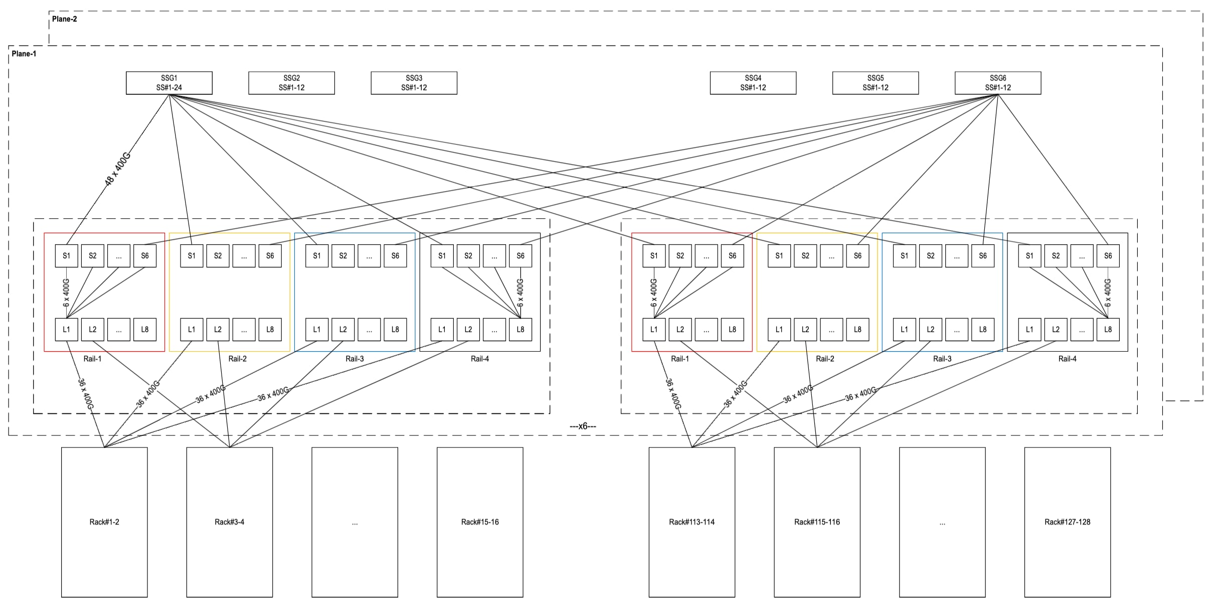
East-West three-tier Compute Network for 128 GB300 racks (9216 GPUs)
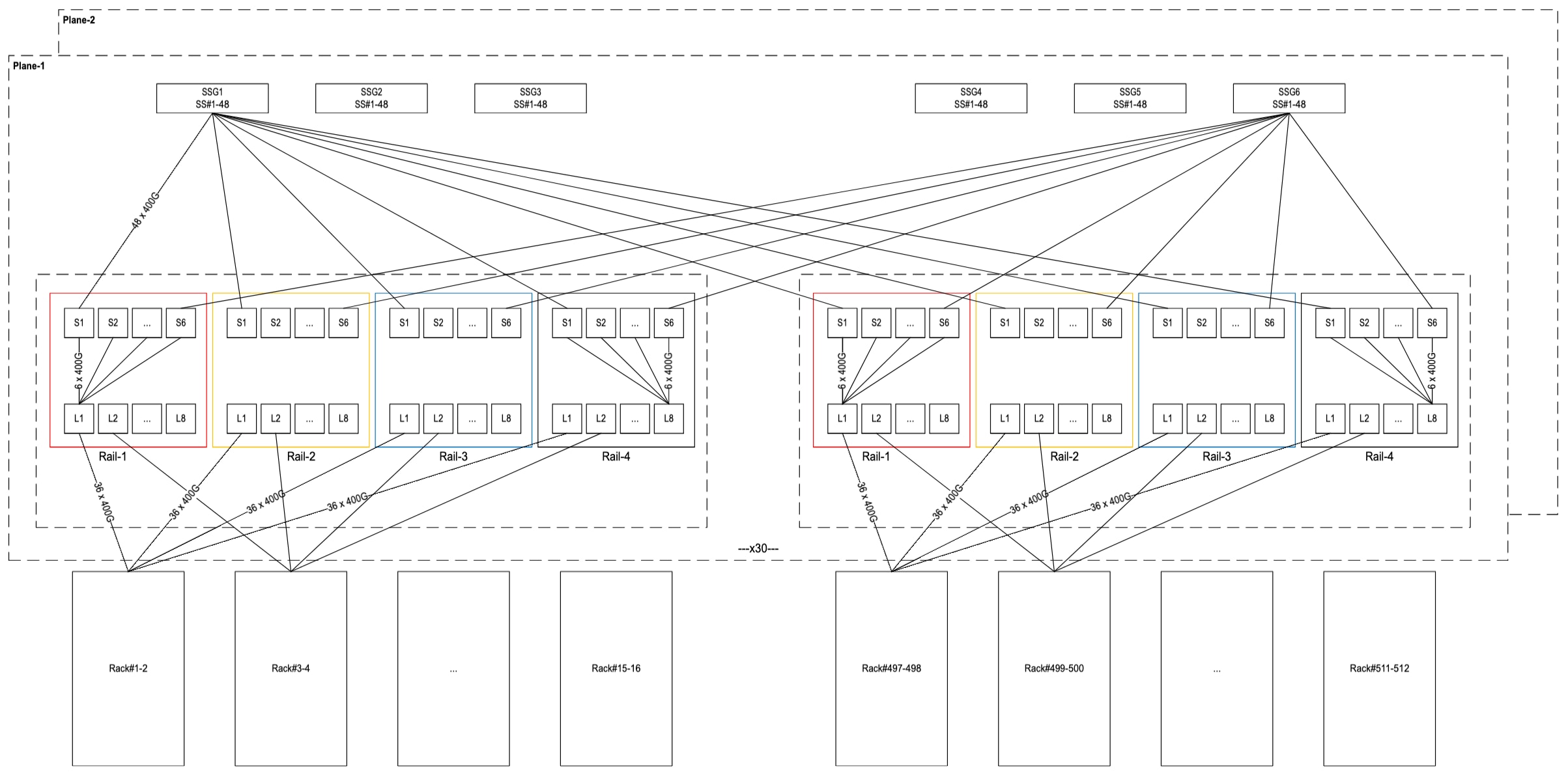
East-West three-tier Compute Network for 512 GB300 racks (36864 GPUs)
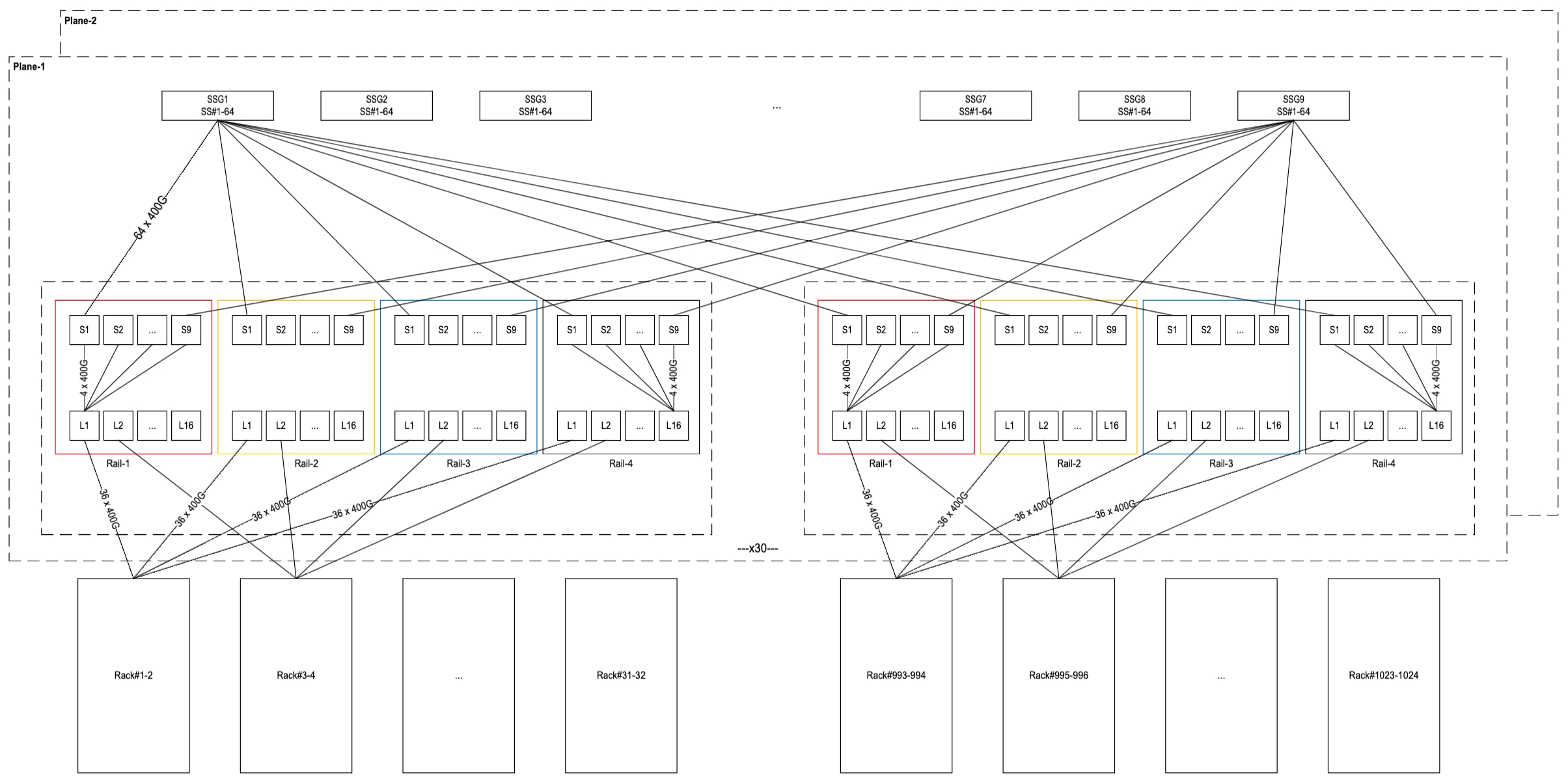
East-West three-tier Compute Network for 1024 GB300 racks (73728 GPUs)
The number of switches, transceivers, and cables required to build the three-tier compute network of different scale ranging from 128 racks or 9216 GPUs to 1024 racks or 73728 GPUs is captured in Table 3.
Table 3. Three-Tier East-West Compute Network Switch, Transceivers, and Cable counts
| Compute counts |
Switch counts |
Transceiver counts |
Cable counts |
||||||||
| Racks |
Nodes |
GPUs |
SUs |
Leaf |
Spine |
SuperSpine |
Node to Leaf |
Switch to Switch (800G) |
Node to Leaf |
Switch to Switch |
|
| Node |
Leaf |
||||||||||
| 128 |
2304 |
9216 |
64 |
512 |
384 |
144 |
9216 |
9216 |
36864 |
18432 |
36864 |
| 256 |
4608 |
18432 |
128 |
1024 |
768 |
288 |
18432 |
18432 |
73728 |
36864 |
73728 |
| 512 |
9216 |
36864 |
256 |
2048 |
1536 |
576 |
36864 |
36864 |
147456 |
73728 |
147456 |
| 1024 |
18432 |
73728 |
512 |
4096 |
2304 |
1152 |
73728 |
73728 |
294912 |
147456 |
294912 |
Converged North-South storage and management network
The converged North-South network is separate from the East-West Compute Network and serves the following key functions:
● Provides access to high performance storage from compute nodes
● Provides host management related access to compute nodes from Management nodes
● Interconnects with border leaf exit switches to forward traffic in and out of cluster
● Allows interconnecting to additional customer infrastructure such as data lakes, and other nodes for support, monitoring, log collection, etc., that a cloud provider wishes to add.
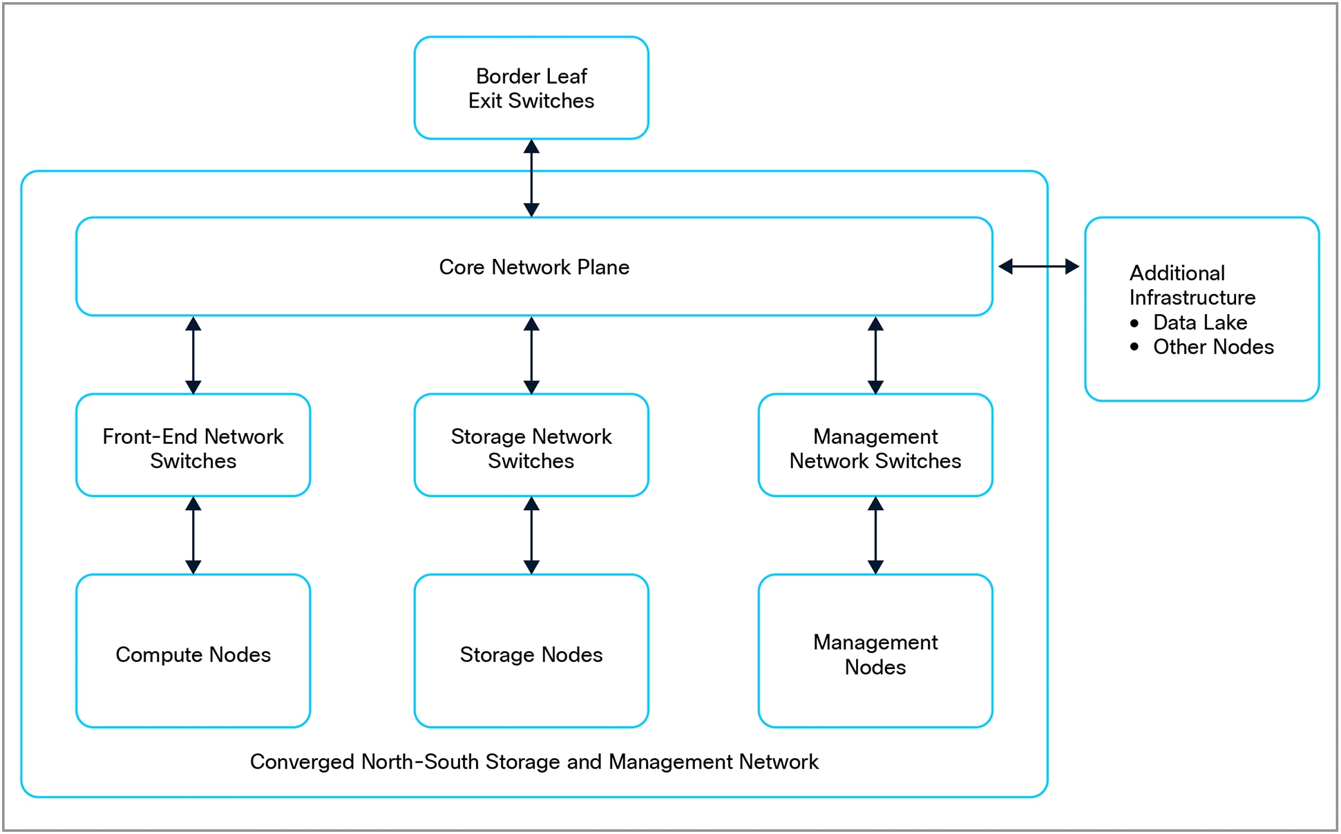
Logical view of Converged North-South Storage and Management Network
Each compute rack has 18 compute trays, and each compute tray has 2 400G ports that need to be connected to a redundant pair of N9364E-SG2-O leaf switches. With two racks, there are a total of 72 400G ports evenly split across two different leaf switches. A group of four racks connected to a pair of leaf switches form a lego building block where each leaf switch has 72 400GE downlinks and 16 uplinks – the 32 400GE uplinks between two leaf switches provide a network bandwidth of 44gbps per GPU within the 4 racks consisting of a total of 288 GPUs. There are two top-of-rack (ToR) switches within each rack that needs to be connected to an OOB network via 2 x 100GE links to allow access to BMC and host management ports of compute trays, NVSwitch trays, power shelves, in-rack Coolant Distribution Unit (CDU) etc.
Each storage server has 2 dual 200GE port NICs for a total of 4 200GE ports. The 2 200GE port per NIC needs to be connected to a redundant pair of N9332D-GX2B storage leaf switches. A group of 16 storage servers connected to two storage leaf switches together for a lego building block where each leaf switch has 32 200GE downlinks and 16 400GE uplinks. The number of storage leaf uplinks can be reduced to 8 for clusters with 8 or less compute racks where a single pair of storage leaf switches is sufficient. Enough network bandwidth to storage is provisioned ensuring 11.1gbps per GPU. Each storage server also requires connecting a 1GE port to server BMC and a 10GE port for server host management.
Each management node has a dual 200GE port NIC connecting to a redundant pair of N9332D-GX2B management leaf switches. About five management nodes are provisioned per 4 racks of 288 GPUs. Additional eight management nodes are allocated for overall cluster management. The number of management nodes can be adjusted as per tenant and cloud provider requirements. The reference design uses a maximum of 48 management nodes per management leaf pair as a lego block with additional blocks added with increase in the number of compute racks beyond 32. Each management node also requires connecting a 1GE port to server BMC and a 10GE port for server host management.
The physical design of the converged network uses a two-tier topology till 128 racks (9216 GPUs) and a three-tier topology beyond that scale.
Two-tier Topology
As shown in Figure 17 to 20, the two-tier design uses a two-stage leaf-spine Clos topology with the spine layer shared between compute, storage, and management layers and also interconnects to the border leaf switches. The entire topology is built using the lego block concept and sizing rules described previously where the number of storage and management nodes are adjusted as per the number of compute racks (GPUs) deployed in the cluster.
As shown in Figure 17, an 8-compute rack (576 GPUs) cluster requires 2 N9364E-SG2-O spine switches, 4 front-end (FE) leaf switches. Each FE leaf uses 72 400GE downlink ports and 16 400GE uplink ports, with a total of 64 400GE across all FE leaf switches providing 44.4gbps of network bandwidth per GPU. This is paired with a single pair of storage leaf switches each with 8 400GE (total of 16 400GE with 2 leaf switches) uplinks providing 11.1gbps per GPU of network bandwidth to storage. A total of 18 management nodes with a single pair of management leaf switches with 2 400GE uplinks, one to each spine, are provisioned. The 16 100GE ports from compute rack ToR switches, the 1 GE and 10 GE ports from storage and management nodes are connected to the OOB management network.
As shown in Figure 18, a 16-compute rack (1152 GPUs) cluster requires 4 N9364E-SG2-O spine switches, 8 front-end (FE) leaf switches. Each FE leaf uses 72 400GE downlink ports and 16 400GE uplink ports, with a total of 128 400GE across all FE leaf switches providing 44.4gbps of network bandwidth per GPU. This is paired with two pairs of storage leaf switches each with 16 400GE (total of 64 400GE with 4 leaf switches) uplinks providing 11.1gbps per GPU of network bandwidth to storage with additional 50% bandwidth reserved for inter storage node communication. A total of 28 management nodes with a single pair of management leaf switches with 4 400GE uplinks, one to each spine, are provisioned. The 32 100GE ports from compute rack ToR switches, the 1 GE and 10 GE ports from storage and management nodes are connected to the OOB management network.
As shown in Figure 19 and 20, the above pattern continues to scale for clusters with 64 (4608 GPUs) and 128 (9216 GPUs) compute racks respectively.
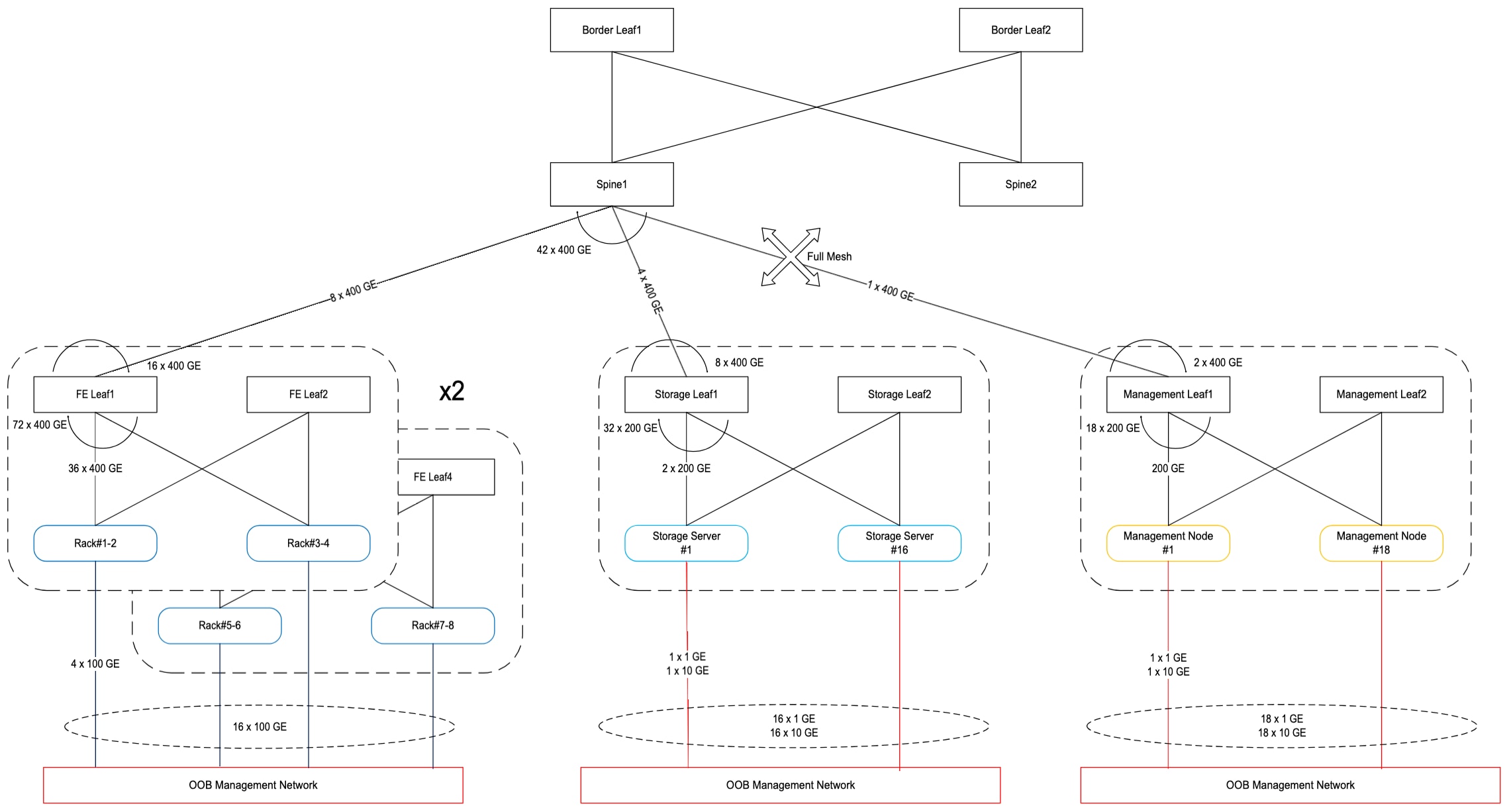
Converged North-South Storage and Management Network for 8 GB300 racks (576 GPUs)
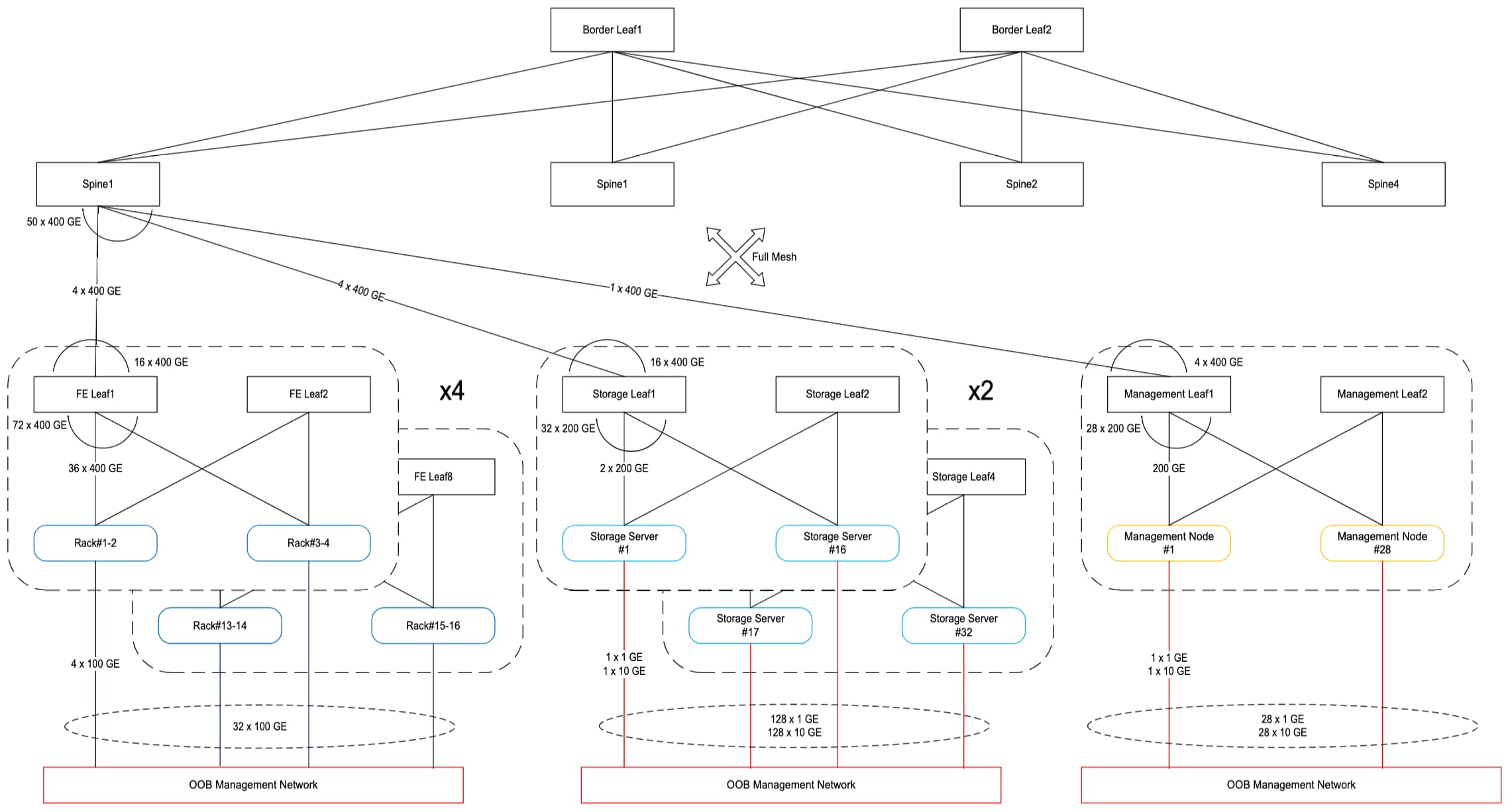
Converged North-South Storage and Management Network for 16 GB300 racks (1152 GPUs)
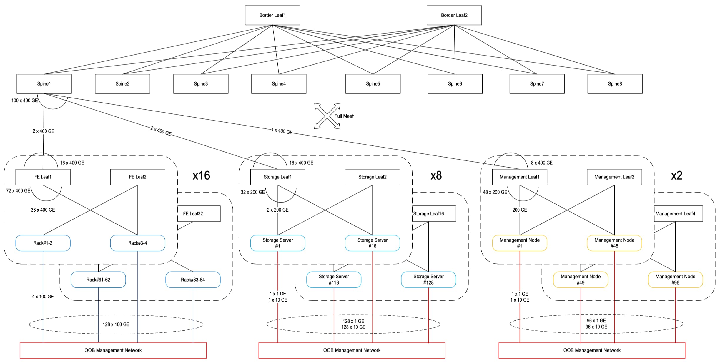
Converged North-South Storage and Management Network for 64 GB300 racks (4608 GPUs)
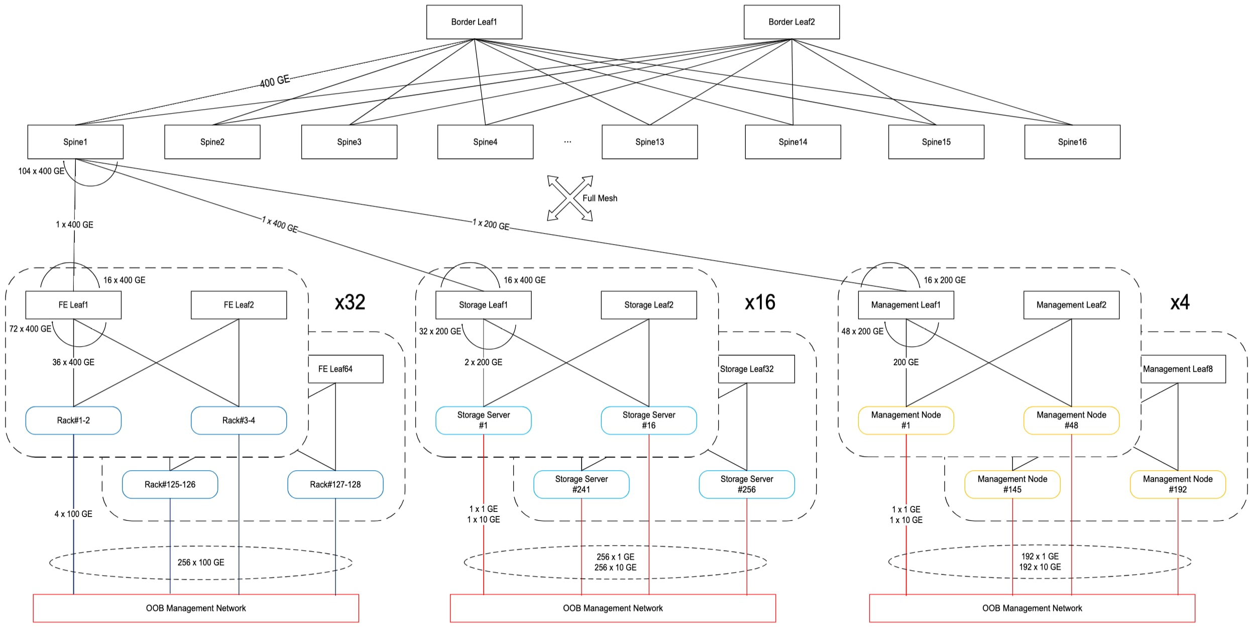
Converged North-South Storage and Management Network for 128 GB300 racks (9216 GPUs)
Three-tier Topology
Beyond 128 compute racks (9216 GPUs), a three-stage Clos topology is used with the third stage represented by four core groups of switches also known as core fabric. The compute, storage and management groups each have their own dedicated spine layer connecting to the core fabric. The N9364E-SG2-O switches are used in all spine layers and core fabric.
The compute layer uses the same lego block concept as described before with the deviation that per FE leaf uplink is increased from 16 to 32 400GE ports. A larger lego super building block is used with 4 smaller compute lego blocks described before with each of them interconnected by 4 FE spine switches – together this bigger lego block consists of 16 compute racks (1152 GPUs), 4 pairs of FE leaf switches (total of 8), and 4 FE spine switches. Each of the 4 FE spine switches have 64 400GE downlinks and their uplinks connect to their respective core group via 16 400 GE ports for a total of 64 400GE uplinks across all 4 FE spine switches providing 22.22gbps of network bandwidth per GPU.
Similar to compute layer, the storage layer uses the same lego block concept described before with storage leaf switches in each block connecting to all four-storage spine group of switches. Each storage spine connects to its respective core group via 64 400GE uplinks. The management layer uses a similar approach with uplinks of management spine switches connecting to a pair of core groups.
As shown in Figure 20, a 256-compute rack (18432 GPUs) cluster requires 4 switches per core group and 2 switches per storage spine group. The aggregate storage spine to core group uses 512 400GE ports providing network bandwidth of 11.1gbps per GPU. Overall, there are 128 FE leaf, 64 FE spine, 8 storage spine, 32 storage leaf, 2 management spine, 16 management leaf, and 16 core group switches. There are 512 100GE from compute racks ToR switch uplinks, 256 1GE and 256 10GE from storage servers, 384 1GE and 384 10GE from management nodes that need to be connected to the OOB network.
As shown in Figure 21, a 512-compute rack (36864 GPUs) cluster requires 8 switches per core group and 4 switches per storage spine group. The aggregate storage spine to core group uses 1024 400GE ports providing network bandwidth of 11.1gbps per GPU. Overall, there are 256 FE leaf, 128 FE spine, 16 storage spine, 64 storage leaf, 2 management spine, 32 management leaf, and 32 core group switches. There are 1024 100GE from compute racks ToR switch uplinks, 256 1GE and 256 10GE from storage servers, 384 1GE and 384 10GE from management nodes that need to be connected to the OOB network.
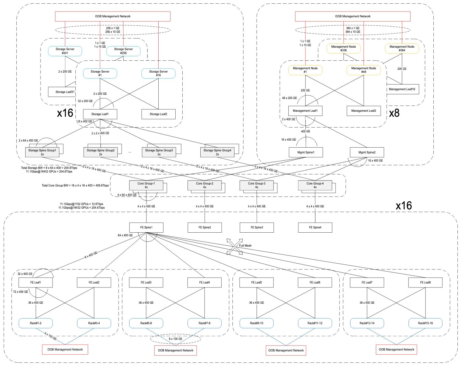
Converged North-South Storage and Management Network for 256 GB300 nodes (18432 GPUs)
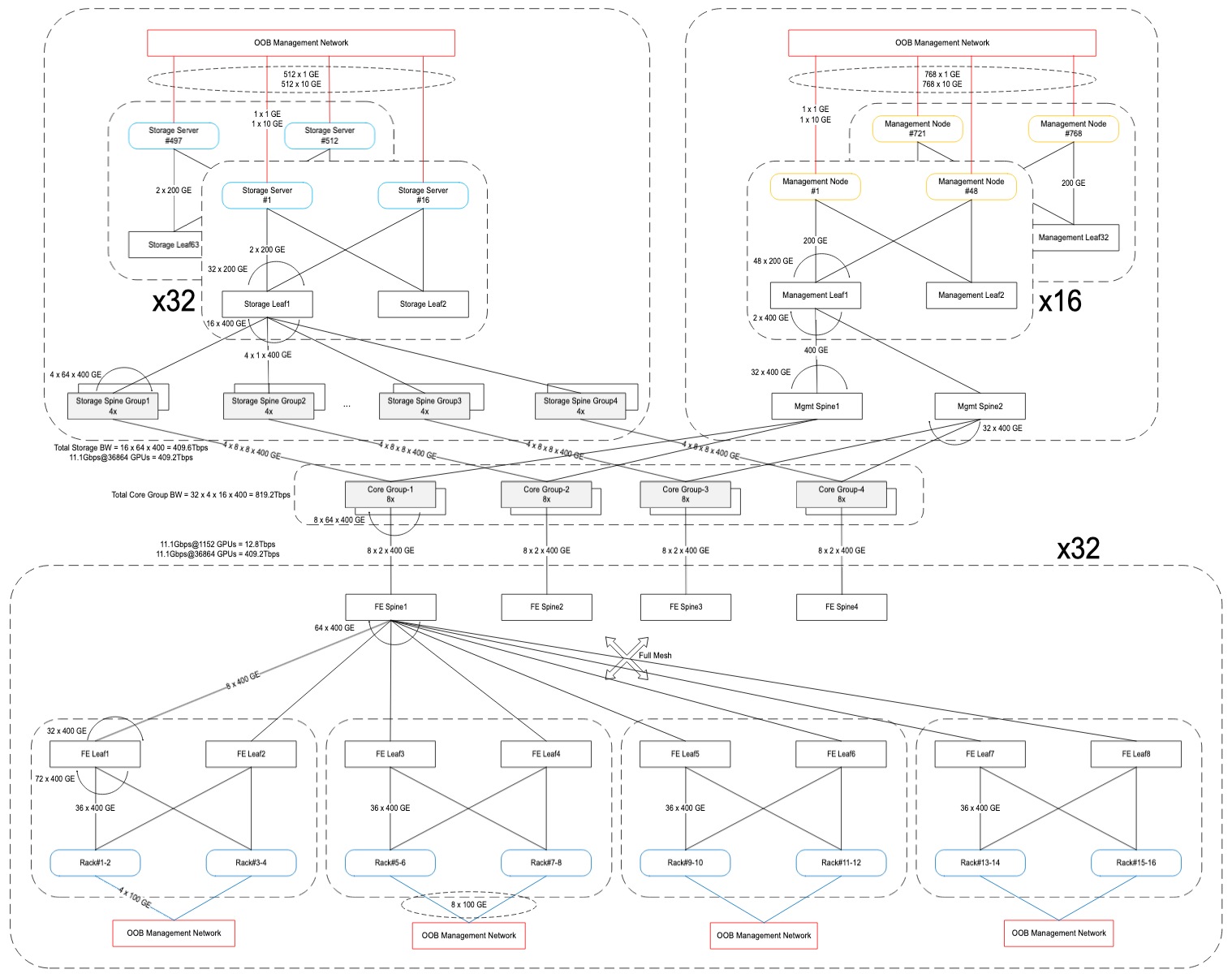
Converged North-South Storage and Management Network for 512 GB300 nodes (36864 GPUs)
Out-of-Band management network
The OOB management network is used to connect the:
● 100 GE compute rack ToR switch uplinks to allow access to BMC and host management ports for all entities in the compute rack such as:
o BMC and host management ports of compute tray, NVSwitch tray
o BMC port of power shelves
o BMC port of NVIDIA Bluefield®-3 DPUs
o BMC port of in-rack CDU
● NVLink Management Software Manager (NMX-M) and NVIDIA Mission Control (NMC) nodes
● 1G BMC and 10G host ports of storage, and management nodes
● 1G management port of Power Distribution Units (PDUs)
● Flow valve RS485 Ethernet gateway ports
● 1G management port of Terminal servers used for equipment console connectivity
This network is not exposed to the tenants. However, it is made accessible to controllers for provisioning, observability, and overall cluster management. Additionally, the 1G management ports of switches need to be connected to OOB or a separate switch management network and made accessible to the on-premises network controller to allow configuration and monitoring. Switch N9396T12C-SE1 (for 1G, 10G) and N9336C-SE1 (for 100G) are used as OOB management leaf and N9364E-SG2-O as OOB management spine switch. The OOB network is also connected to data center’s Building Management System (BMS) to forward sensor data, leak detection alarms allowing timely flow valve and power cut off when required.
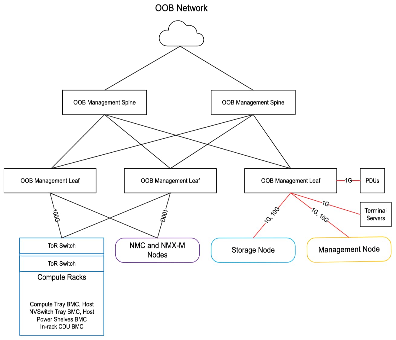
OOB Management Network
Table 4 shows the Bill-of-Materials (BOM) for building clusters with different counts of GB300 NLV72 compute racks (GPUs).
Table 4. Minimum BOM for clusters with different counts of GB300 NVL72 compute racks (GPUs)
| PID |
Description |
576 GPUs |
1152 GPUs |
4608 GPUs |
9216 GPUs |
18432 GPUs |
36864 GPUs |
| SRS-GB300-NVL72 |
Supermicro GB300 NVL72 rack |
8 |
16 |
64 |
128 |
256 |
512 |
| N9364E-SG2-O (Converged network only use case) |
Cisco N9000 switch, 64x800Gbps OSFP |
6 |
12 |
40 |
80 |
218 |
434 |
| N9164E-NS4-O (East-West compute network only use case) |
Cisco N9000 switch, 64x800Gbps OSFP |
44 |
82 |
328 |
1040 |
2080 |
4160 |
| N9364E-SG2-O (Both East-West compute & Converged network use case) |
Cisco N9000 switch, 64x800Gbps OSFP |
50 |
94 |
368 |
1120 |
2298 |
4594 |
| N9K-C9332D-GX2B (Storage and Management leaf) |
Cisco Nexus switch, 32x400Gbps QSFP-DD |
4 |
6 |
20 |
40 |
48 |
96 |
| N9396T12C-SE1 (OOB low-speed management leaf) |
Cisco N9000 switch, 96 1/10GBASE-T 12 QSFP28 |
1 |
2 |
5 |
10 |
14 |
27 |
| N9336C-SE1 (OOB high-speed management leaf) |
Cisco N9000 switch, 36x100Gbps QSFP28 |
2 |
2 |
8 |
16 |
32 |
64 |
| N9364E-SG2-O (OOB management spine) |
Cisco N9000 switch, 64x800Gbps OSFP |
2 |
2 |
2 |
2 |
2 |
2 |
| OSFP-800G-DR8 |
800G OSFP transceiver, 800GBASE-DR8, SMF dual MPO-12 APC, 500m |
1948 |
3910 |
15636 |
49736 |
102716 |
205432 |
| OSFPR-800G-DR8 |
800G OSFP transceiver, 800GBASE-DR8, SMF dual MPO-12 APC, 500m (riding heat sink) |
576 |
1152 |
4608 |
9216 |
18432 |
36864 |
| QDD-400G-DR4 |
400G QSFP-DD transceiver, 400GBASE-DR4, MPO-12, 500m parallel |
20 |
72 |
288 |
576 |
544 |
1088 |
| QSFP-400G-DR4 |
400G QSFP112 transceiver, 400GBASE-DR4, MPO-12, 500m parallel |
288 |
576 |
2304 |
4608 |
9216 |
18432 |
| QDD-400G-SR8-S |
400G QSFP-DD transceiver, 400GBASE-SR8, MPO-16 APC, 100m |
50 |
92 |
352 |
704 |
896 |
1792 |
| QSFP-200G-SR4-S |
200G QSFP transceiver, 200GBASE-SR4, MPO-12, 100m |
100 |
184 |
704 |
1408 |
1792 |
3584 |
| QSFP-100G-DR-S |
100G QSFP transceiver, 100GBASE-DR, LC, 500m |
38 |
72 |
282 |
564 |
1116 |
2230 |
| CB-M12-M12-SMF |
MPO-12 cables |
2676 |
5384 |
21536 |
61568 |
126016 |
252032 |
| CB-M16-M12-MMF |
MPO-16 to dual MPO-12 breakout cables |
50 |
92 |
352 |
704 |
896 |
1792 |
| CB-LC-LC-SMF |
Duplex LC-LC Cables |
32 |
64 |
256 |
512 |
1024 |
2048 |
| CB-M12-4LC-SMF |
MPO-12 to 4x duplex LC, breakout cable, SMF |
2 |
2 |
7 |
13 |
23 |
46 |
| CAT6A |
Copper cable for 10G |
34 |
60 |
224 |
448 |
640 |
1280 |
| CAT5E |
Copper cable for 1G |
34 |
60 |
224 |
448 |
640 |
1280 |
| UCSC-C225-M8N (storage server) |
Cisco UCS C225-M8 1RU Rack Server |
Min: 12 Max: 16 |
Min: 12 Max: 32 |
Min: 48 Max: 128 |
Min: 96 Max: 256 |
Min: 192 Max: 256 |
Min: 384 Max: 512 |
| UCSC-C240-M8 UCSC-C245-M8SX (management node) |
Cisco UCS C240-M8 2RU Rack Server Cisco UCS C245-M8 2RU Rack Server |
18 |
28 |
96 |
192 |
384 |
768 |
The entire networking fabric is configured using VXLAN data-plane and BGP EVPN control-plane enabling native support for multitenancy. All resources assigned to the tenants, such as bare metal or virtualized computes nodes, management nodes, and access to storage, are completely isolated. Multitenancy is supported throughout the fabric via L2 or L3 segmentation. Every leaf switch host facing port can be assigned to the appropriate VLAN, VNI and VRF to isolate tenant traffic.
There are two VRFs whose access is limited to the CSP and direct access to them is not allowed to the tenants:
1. Out-of-Band (OOB) Management Network: vrfOOBMgmt VRF.
2. Storage Internal Network: vrfStorageInternal VRF.
Storage Internal network
As described in the “High-Performance Storage” section, every storage node has 2 DPUs where NIC-0 is used for internal storage server to storage server communication and NIC-1 is used for external communication to clients such as compute nodes, management nodes etc. The ports on NIC-0 of all storage servers are part of a separate vrfStorageInternal VRF whose access is limited only to the CSP and not allowed to the tenants.
Every tenant is allocated at least two VRFs:
1. Compute Network: vrf<Tenant>Backend VRF.
2. Converged Storage and Management Network: vrf<Tenant>Frontend VRF.
Compute network
The routes in the backend East-West network of compute nodes assigned to a tenant are isolated into vrf<Tenant>Backend VRF.
Converged storage and management network
For every tenant, a separate tenant account is created in the high-performance storage, thereby allowing further provisioning of storage resources assigned to the tenant. A separate VLAN is also assigned to isolate tenant's storage access from the compute and management nodes assigned to the tenant. This VLAN’s VxLAN VNI is part of vrf<Tenant>Frontend VRF.
Workload orchestration
Each tenant is assigned a group of management nodes that can be used for:
● Provisioning the compute nodes either via NVIDIA Base Command Manager (BCM) or additional provisioning tools/frameworks.
● Setup Slurm and/or Kubernetes control nodes for orchestrating jobs on worker compute nodes.
● Additional infrastructure for observability, monitoring, and logs collections.
These management nodes are accessible to the tenant via the vrf<Tenant>Frontend VRF.
The converged fabric connects to two or more border leaf switches with a redundant number of links to allow forwarding data into and out of the cluster. The border leaf switches perform L3 routing while all VxLAN encapsulation and decapsulation are done inside the converged network fabric. The number of border leaf switches, the number of links between them and the converged network fabric, the networking feature sets enabled on them would vary as per customer use case and are beyond the scope of this RA.
Cisco has partnered with VAST Data to onboard their AI OS on Cisco UCS C225-M8N Rack Servers in EBox architecture: together, they provide the storage subsystem for this RA. This product is called Cisco EBox and it is NVIDIA-Certified high-performance storage for both NCP and Cisco Cloud Reference Architecture based large GPU scale Secure AI Factory. VAST Data supports a “Distributed and Shared Everything” (DASE) architecture that allows for horizontally scaling storage capacity and read/write performance by incrementally adding servers to a single namespace. This allows building clusters of different sizes with varying number of storage servers. Additional features include native support for multitenancy, multiprotocol (NFS, S3, SMB), data reduction, data protection, cluster high availability, serviceability of failed hardware components etc.
Figure 24 shows the overall network connectivity of storage servers. For data path, each server uses two NVIDIA BlueField®-3 B3220L 2x200G DPUs – NIC0 is used for internal network within the servers allowing any server to access storage drives from any other server, NIC1 is used for external network supporting client traffic such as NFS, S3, SMB. The 1G BMC and 10G x86 management ports are connected to a management leaf switch.
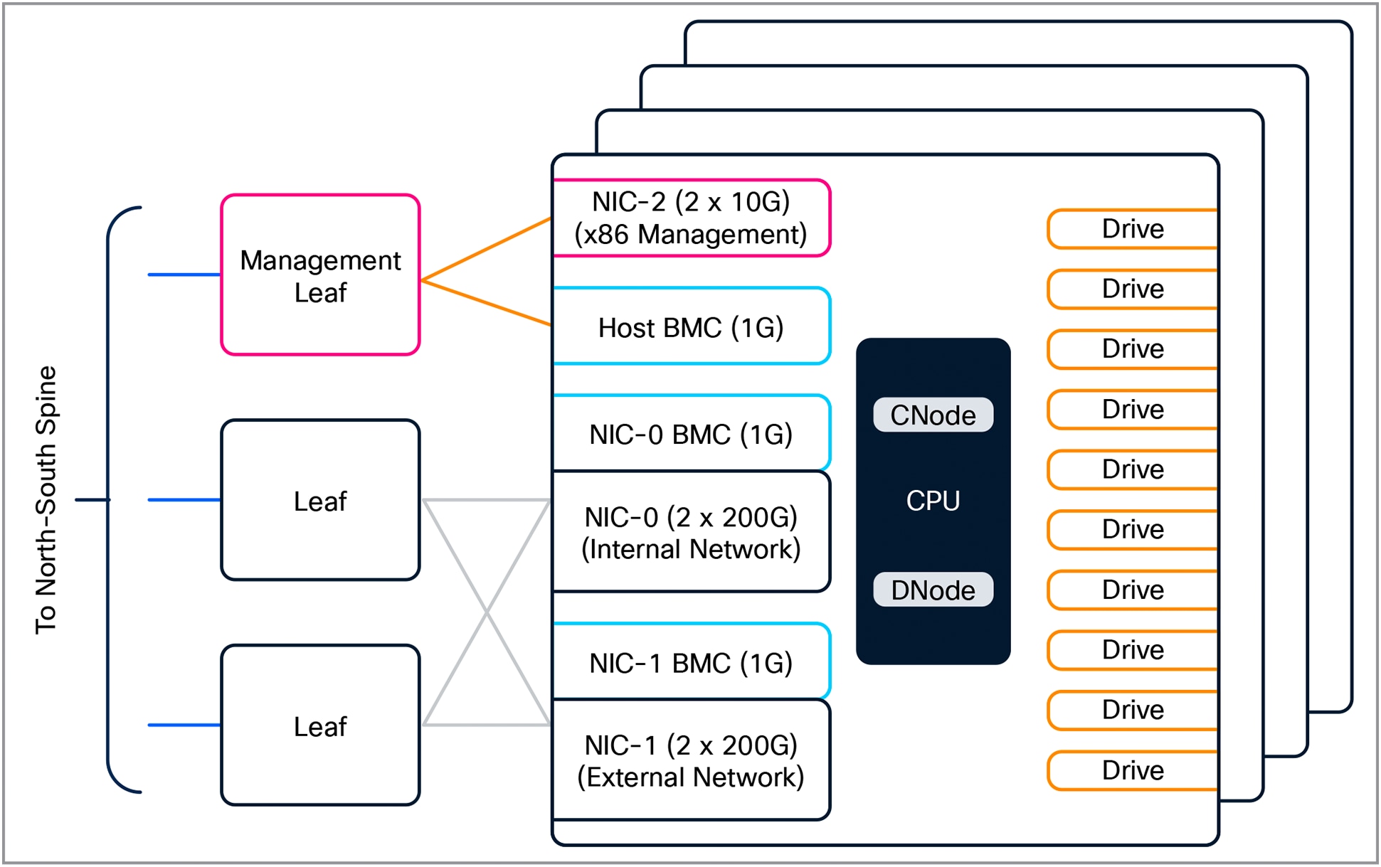
Cisco EBox Storage Logical Block Diagram
Beside the Cisco EBox, this RA will support all NVIDIA-Certified high-performance storage solutions certified till the NCP level and supporting multi-tenancy.
To deploy and manage a high-scale AI cluster, a robust software stack is required with an automation-first approach. The use of controllers along with their programmability interfaces can tremendously simplify day-0 resource provisioning, day-1 configuration, and day-N operationalization. The following sub-sections cover the key software components involved in this reference architecture.
Network controller
Cisco Nexus Dashboard can be used to provision and manage the entire networking fabric including the provisioning required for tenants. It offers a unified platform that integrates key services — Insights (visibility and telemetry), Orchestrator (orchestration), and Fabric Controller (automation) — to deliver comprehensive network visibility, automation, and operational simplicity. CSPs can also manage the switches and overall networking via open-source tools such as Ansible, Chef, and Puppet, integrating them with available programmability interfaces.
Compute controller
NVIDIA Mission Control paired with NVIDIA Base Command Manager and NVLink Management software manager are essential for deploying and managing GB300 NVL72 systems, providing centralized provisioning, configuration, autonomous hardware recovery, and deep observability. They automate firmware updates, monitor liquid cooling, and manage the high-speed NVLink fabric, maximizing uptime for the overall compute infrastructure.
Storage controller
The Cisco EBox storage controller (also known as VAST Management Service) will be used for provisioning and managing the attached high-performance storage. Besides this, cloud partner and every tenant is also allocated a storage management URL, a user login, and a dashboard for configuration, monitoring, and overall management. RESTful APIs are supported for integration with automation frameworks.
NVIDIA AI Enterprise and Spectrum-X
This reference architecture includes NVIDIA AI Enterprise, deployed and supported on NVIDIA-Certified Supermicro GB300 NVL72 racks. NVIDIA AI Enterprise is a cloud-native suite of software tools, libraries, and frameworks designed to deliver optimized performance, robust security, and stability for production AI deployments. Easy-to-use microservices enhances model performance with enterprise-grade security, support, and stability, ensuring a smooth transition from prototype to production for enterprises that run their businesses on AI.
NVIDIA NIM™ is a set of easy-to-use microservices designed for secure, reliable deployment of high-performance AI model inferencing across clouds, data centers, and workstations. Supporting a wide range of AI models, including open-source community and NVIDIA AI foundation models, it ensures seamless, scalable AI inferencing on premises and in the cloud with industry-standard APIs.
NVIDIA® Spectrum™-X Ethernet Networking Platform, featuring Spectrum™-X Ethernet switches and Spectrum™-X Ethernet SuperNICs, is the world’s first Ethernet fabric built for AI, accelerating generative AI network performance by 1.6x. Its benefits are available with Cisco SiliconOne based N9364E-SG2-O switches used in this RA when connected to NVIDIA®-8 and enabled with Fine Grain Load Balancing (FGLB) license. The Spectrum-X license is not required when deploying East-West compute network with the use of N9164E-NS4-O switch.
Security in a multitenant AI infrastructure is very crucial to ensure confidentiality, integrity, and high availability against adversarial attacks by implementing robust access controls and host and network isolation to prevent unauthorized access or manipulation. Several Cisco security technologies, as enumerated below, are available that can be deployed by CSPs and tenants to configure, monitor, and enforce end-to-end security right from applications to overall infrastructure. The complete integration of these technologies into the end-to-end workflow is beyond the scope of this RA.
Observability is a key element of AI infrastructure to ensure continuous visibility and reliability and to provide high-performance by tuning as well as proper infrastructure scaling. It also facilitates debugging, aids security, and helps maintain trustworthy and effective AI systems. Cisco Splunk® is an industry-leading observability solution for cloud partners as well as for tenants to ingest significant amounts of telemetry and gain in-depth visibility. It’s integration within the end-to-end workflow is beyond the scope of this RA.
The overall solution has been thoroughly tested considering all aspects of management plane, control plane, and data plane combining compute, storage, and networking together. The compute nodes are NVIDIA-Certified Systems™. The Cisco EBox high-performance storage solution has achieved NVIDIA-Certified Storage validation at the NCP level. Several benchmark test suites such as HPC Benchmark, single and multi-hop IB PerfTest, NCCL collective communications tests, and high-availability (across switch and link failure) tests, MLCommons Training and Inference benchmarks have also been run to evaluate end-to-end performance and assist with tuning. Different elements and entities of the NVIDIA AI Enterprise ecosystem have been brought up with use cases around Model Training, Fine-tuning, Inferencing, and RAG.
In short, the Cisco Cloud Reference Architecture is a fully integrated, end-to-end tested, high-GPU scale multitenant AI cluster solution offering cloud partners a one-stop shop place for their AI infrastructure deployment needs.