Use of Mode Conditioning Patch Cables in Gigabit Ethernet and 10 Gigabit Ethernet Laser-Based Transmissions
Available Languages
Bias-Free Language
The documentation set for this product strives to use bias-free language. For the purposes of this documentation set, bias-free is defined as language that does not imply discrimination based on age, disability, gender, racial identity, ethnic identity, sexual orientation, socioeconomic status, and intersectionality. Exceptions may be present in the documentation due to language that is hardcoded in the user interfaces of the product software, language used based on RFP documentation, or language that is used by a referenced third-party product. Learn more about how Cisco is using Inclusive Language.
PB530836
This bulletin describes the necessary steps to help ensure that Gigabit and 10 Gigabit Ethernet laser-based transmissions over multimode fiber (MMF) are successfully implemented and supported. It depicts the requirements for mode conditioning patch (MCP) cables.
Cisco Transceiver Modules and Mode Conditioning Patch cables
The transceiver modules affected by the requirement of MCP are described in Table 1.
Table 1. Optical Transceivers
| Product Number |
Product Description |
| WS-G5486= |
Cisco 1000BASE-LX/LH GBIC transceiver module for SMF and MMF, 1300-nm wavelength, commercial operating temperature range, 32°F to 158°F (0°C to 70°C) |
| GLC-LH-SM= |
Cisco 1000BASE-LX/LH SFP transceiver module for SMF and MMF, 1300-nm wavelength, commercial operating temperature range, 32°F to 158°F (0°C to 70°C) |
| SFP-GE-L= |
Cisco 1000BASE-LX/LH SFP transceiver module for SMF and MMF, 1300-nm wavelength, extended operating temperature range, 23°F to 185°F (-5°C to 85°C) |
| GLC-LX-SM-RGD= |
Cisco 1000BASE-LX/LH SFP transceiver module for SMF and MMF, 1300-nm wavelength, industrial operating temperature range, -40°F to 185°F (-40°C to 85°C) |
| X2-10GB-LX4= |
Cisco 10GBASE-LX4 X2 Module for MMF, 1300-nm WWDM wavelength, commercial operating temperature range, 32°F to 158°F (0°C to 70°C) |
| XENPAK-10GB-LX4= |
Cisco 10GBASE-LX4 XENPAK Module for MMF, 1300-nm WWDM wavelength, commercial operating temperature range, 32°F to 158°F (0°C to 70°C) |
| X2-10GB-LRM= |
Cisco 10GBASE-LRM X2 Module for MMF, 1300-nm wavelength, commercial operating temperature range, 32°F to 158°F (0°C to 70°C) |
| XENPAK-10GB-LRM= |
Cisco 10GBASE-LRM XENPAK Module for MMF, 1300-nm wavelength, commercial operating temperature range, 32°F to 158°F (0°C to 70°C) |
| SFP-10G-LRM= |
Cisco 10GBASE-LRM SFP+Module for MMF, 1300-nm wavelength, commercial temperature range, 32°F to 158°F |
|
|
(0°C to 70°C) |
Table 2 describes the MCP cables offered by Cisco. Note there are mainly two types of MCP respectively for applications over 62.5-micron MMF and 50-micron MMF.
Table 2. Mode Conditioning Patch Cables
| Product Number |
Product Description |
| CAB-GELX-625= |
IEEE 802.3z-compliant optical fiber assembly consisting of a single-mode fiber permanently coupled off-center to a |
|
|
62.5-micron multimode optical fiber with duplex SC connectors at both ends. The patch cord is 3 meters (9.84 feet) in length. |
| CAB-MCP50-SC= |
IEEE 802.3z-compliant optical fiber assembly consisting of a single-mode fiber permanently coupled off-center to a 50-micron multimode optical fiber with duplex SC connectors at both ends. The patch cord is 1 meter (3.28 feet) in length. |
| CAB-MCP-LC= |
IEEE 802.3z-compliant optical fiber assembly consisting of a single-mode fiber permanently coupled off-center to a 62.5-micron multimode optical fiber with duplex SC connectors at one end and duplex LC connectors at the other end. The patch cord is 1 meter (3.28 feet) in length. |
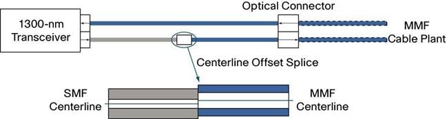
Figure 1 shows an MCP and how it is typically connected to a transceiver module. When required, it is inserted between a transceiver module and the MMF cable plant.
Types of Multimode Fiber
Table 3 provides a brief overview and naming conventions of various MMF types deployed in the field.
Table 3. Types of MMF
| Naming Convention |
Core Size in Microns |
Modal Bandwidth at 850 nm (MHz*km) |
OFL Modal Bandwidth at 1310 nm (MHz*km) |
| FDDI-grade |
62.5 |
160 |
500 |
| OM1 |
62.5 |
200 |
500 |
| OM2 |
50 |
500 |
500 |
| OM3 |
50 |
1500 |
500 |
Requirements for Gigabit Ethernet Transmissions
The requirement for MCP is specified only for 1000BASE-LX/LH transceivers transmitting in the 1300-nm window and in applications over MMF. MCP should never be used in 1000BASE-SX links in the 850-nm window.
MCP is required for 1000BASE-LX/LH applications over FDDI-grade, OM1, and OM2 fiber types. MCP should never be used for applications over OM3, also known as “laser-optimized fiber.”
Note:
1. In some cases, customers might experience that a link would be operating properly over FDDI-grade, OM1 or OM2 fiber types without MCP. However please note there is no guarantee link will be operating properly over time, and the recommendation remains to use the MCP.
2. There is a risk associated to this type of nonstandard deployment without MCP, especially when the jumper cable is an FDDI-grade or OM1 type. In such case the power coupled directly into a 62.5-micron fiber could be as high as a few dBm and the adjacent receiver will be saturated. This can cause high bit error rate, link flaps, link down status and eventually irreversible damaged to the device.
3. In the event customers remain reluctant to deploy MCP cables, and for customers using OM3 cables, please measure the power level before plugging the fiber into the adjacent receiver. When the received power is measured above -3dBm, a 5-dB attenuator for 1300nm should be used and plugged at the transmitter source of the optical module on each side of the link.
4. Another alternative for short reaches within the same location is to use a single-mode patch cable. There will be no saturation over single-mode fiber.
Requirements for 10 Gigabit Ethernet Transmissions
The requirement for MCP is specified only for 10GBASE-LX4 and 10GBASE-LRM transceivers transmitting in the 1300-nm window and in applications over MMF. MCP should never be used in 10GBASE-SR links in the 850-nm window.
MCP is required for 10GBASE-LX4 and 10GBASE-LRM applications over FDDI-grade, OM1, and OM2 fiber types. MCP should never be used for applications over OM3, also known as “laser-optimized fiber.”
Notes for LX4:
1. In some cases, customers might experience that a link would be operating properly over OM2 fiber type without MCP. However chances of experiencing a properly operating link over FDDI-grade or OM1 fiber types without MCP are very low.
2. In the event customers remain reluctant to deploy MCP cables over OM2, and for customers using OM3 cables, it is required to a plug a 5-dB attenuator for 1300nm at the transmitter source of the optical module on each side of the link in order to avoid saturation, and potential subsequent link flaps and damage to the device.
3. Another alternative for short reaches within the same location is to use a single-mode patch cable. There will be no saturation over single-mode fiber. Please note the 10GBASE-LX4 devices can reach up to 10km over single-mode fiber as per compliance to IEEE.
Notes for LRM:
1. For customers using OM3 fiber type, MCP should not be used. It is highly recommended to measure the power level before plugging the fiber into the adjacent receiver. When the received power is measured to be above 0.5dBm, a 5-dB attenuator for 1300nm should be used and plugged at the transmitter source of the optical module on each side of the link.
2. Another alternative for short reaches within the same location is to use a single-mode patch cable. There will be no saturation over single-mode fiber. Please note the 10GBASE-LRM devices can reach up to 300m over single-mode fiber as per Cisco specifications.