-
Cisco MDS 9000 Family Fabric Manager Configuration Guide, Release 3.x
-
Index
-
New and Changed Information
-
Preface
- Getting Started
- Installation and Switch Management
- Switch Configuration
-
Fabric Configuration
-
Configuring and Managing VSANs
-
SAN Device Virtualization
-
Creating Dynamic VSANs
-
Configuring Inter-VSAN Routing
-
Distributing Device Alias Services
-
Configuring and Managing Zones
-
Configuring Fibre Channel Routing Services and Protocols
-
Dense Wavelength Division Multiplexing
-
Managing FLOGI, Name Server, FDMI, and RSCN Databases
-
Discovering SCSI Targets
-
Configuring FICON
-
Advanced Features and Concepts
-
-
Security
-
Configuring FIPS
-
Configuring Users and Common Roles
-
Configuring SNMP
-
Configuring RADIUS and TACACS+
-
Configuring IPv4 Access Control Lists
-
Configuring Certificate Authorities and Digital Certificates
-
Configuring IPsec Network Security
-
Configuring FC-SP and DHCHAP
-
Configuring Port Security
-
Configuring Fabric Binding
-
- IP Services
- Intelligent Storage Services
- Network and Switch Monitoring
- Traffic Management
- Troubleshooting
-
Launching Fabric Manager in Cisco SAN-OS Releases Prior to 3.2(1)
-
Cisco Fabric Manager Unsupported Feature List
-
Interface Nonoperational Reason Codes
-
Managing Cisco FabricWare
-
Configuration Limits for Cisco MDS SAN-OS Release 3.1(x) and 3.2(x)
-
 Feedback
Table Of Contents
Linking a Virtual Device with a Physical Device
Resolving Fabric Merge Conflicts
SDV Requirements and Guidelines
SAN Device Virtualization
This chapter describes how to configure virtual devices to represent physical end devices for switches running Cisco MDS SAN-OS Release 3.1(2) and later.
Cisco SAN device virtualization (SDV) is a licensed feature included in the Cisco MDS 9000 Family Enterprise package (ENTERPRISE_PKG). See Chapter 10, "Obtaining and Installing Licenses," for details about acquiring licenses.
This chapter includes the following sections:
About SDV
As of Cisco SAN-OS Release 3.1(2) and later, you can use Cisco SDV to create virtual devices that represent physical end-devices. Virtualization of SAN devices accelerates swapout or failover to a replacement disk array, and it also minimizes downtime when replacing host bus adapters (HBAs) or when re-hosting an application on a different server.
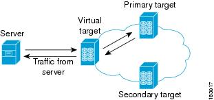
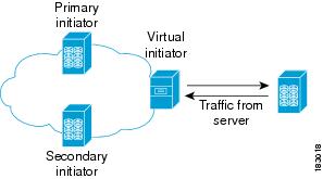
SAN devices that are virtualized can be either initiators or targets. You can virtualize targets to create a virtual target, and also virtualize initiators to create a virtual initiator. Such configurations do not distinguish between virtual initiators and virtual targets (see Figure 27-1 and Figure 27-2).
Figure 27-1 Target Virtualization
Figure 27-2 Initiator Virtualization
Note
While most of the examples in this chapter describe target virtualization, the same behaviors apply to initiator virtualization as well.
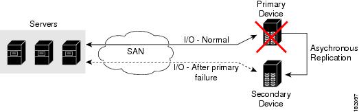
Typically, today's deployments for handling device failures are designed for high availability (HA), with redundancy being a key part of this design. Let's consider the case where a target is designed to be redundant. Here, two arrays are deployed-a primary and secondary. Enterprises often use some type of consistency technology (such as EMF SRDF) between the primary and secondary arrays to ensure that the secondary is a mirrored copy of the production LUN. However, if the primary array fails, it must be replaced by the secondary, as all I/O must occur on the secondary. Problems can occur because the time required to bring the secondary array up and have it working often takes longer than most can afford (Figure 27-3 illustrates this dilemma).
Figure 27-3 Typical Deployment for Handling Device Failures Before SDV
If a storage array is replaced without using Cisco SDV, then it may require the following:
•
•
•
More specifically, without SDV you might experience the following:
•
•
•
SDV enables you to:
•
•
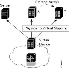
Figure 27-4 illustrates the benefits of SDV. In this configuration, disk array Y replaces disk array X. When disk array X was deployed, the user created virtual devices for all the Fibre Channel interfaces using SDV. After data replication from disk array X was completed, the user briefly pauses activity on the application server and re-linked disk array Y to the virtual devices used by the server, completing the swapout of disk array X. No zoning changes or host operating system configuration changes were required during the time-critical period when the swap was performed; this significantly minimized application downtime.
Note
Figure 27-4 SDV Example
Key Concepts
The following terms are used throughout this chapter:
•
The virtualized or proxy representation of the real device, which is registered with the name server and has a pWWN and FC ID. A virtual device exists as long as its real (physical) counterpart is online. The virtual device pWWN and FC ID must be unique and cannot clash with any real device pWWNs and FC IDs.•
Reserved by SDV to assign FC IDs to virtual devices. If the switch that reserved the domain goes down, another switch takes over its role using the same domain.Configuring SDV
SDV is a distributed service and uses CFS (Cisco Fabric Services) distribution to synchronize the databases. When you configure SDV it starts a CFS session and locks the fabric. When a fabric is locked, Cisco SAN-OS software does not allow any configuration changes from a switch-other than the switch holding the lock-and issues a message to inform users about the locked status. Configuration changes are held in a pending database for the application. You must perform a commit operation to make the configuration active and to release the lock for all switches.
See Chapter 13, "Using the CFS Infrastructure" for more details about CFS,
Note
The following sections describe how to configure SDV:
•
•
Configuring a Virtual Device
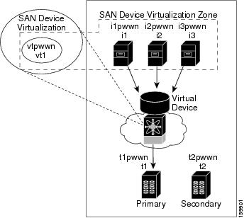
A virtual device is identified by an alphanumeric name of up to 32 characters and defines all the real devices (one primary and one or more secondary) that it represents. Upon the successful creation of a virtual device, the virtual device name is internally registered as the device alias name with the device alias database; the pWWN is automatically assigned by the system using Cisco OUI (Organizational Unique Identifier). A virtual device appears as a real, physical device. You can enumerate up to 128 devices for a virtual device. There is a limit of 4095 on the number of virtual devices that you can create in a single VSAN.
Figure 27-5 shows a configuration that includes a new virtual device, vt1.
Figure 27-5 Creating a Virtual Device
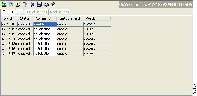
To configure a virtual target and commit it to the fabric configuration using Fabric Manager, follow these steps:
Step 1
Step 2
Step 3
Figure 27-6 Enabling SAN Device Virtualization
Step 4
Step 5
Step 6
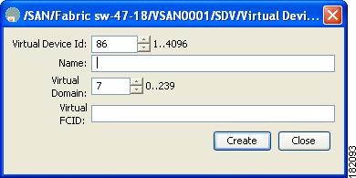
You see the Create Virtual Devices dialog box (see Figure 27-7).
Figure 27-7 Create Virtual Devices Dialog Box
Step 7
Step 8
Step 9
Step 10
Note
For more information, see the "Adding Zone Members" section on page 30-15.
Caution
For example, SDV is enabled on a switch and a virtual device is defined. SDV assigns a pWWN for the virtual device, and it is zoned based on the pWWN in a zone. If you later disable SDV, this configuration is lost. If you reenable SDV and create the virtual device using the same name, there is no guarantee that it will get the same pWWN again. Hence, you would have to rezone the pWWN-based zone. However, if you perform zoning based on the device-alias name, there are no configuration changes required if or when the pWWN changes.
Be sure you understand how device alias modes work before enabling them. Refer to Chapter 24, "Distributing Device Alias Services" for details and requirements about device alias modes.
Linking a Virtual Device with a Physical Device
After creating a virtual device and configuring it as part of a zone, you can define the primary device for it using the link command, which is also used to fail over to the secondary device.
Note
To link a virtual target with a physical target using Fabric Manager, follow these steps:
Step 1
Step 2
Step 3
Figure 27-8 Create Real Devices Dialog Box
Step 4
Step 5
Step 6
Resolving Fabric Merge Conflicts
Whenever two fabrics merge SDV merges its database. A merge conflict can occur when there is a run-time information conflict or configuration mismatch. Run-time conflicts can occur do to:
•
•
•
A blank commit is a commit operation that does not contain configuration changes, and enforces the SDV configuration of the committing switch fabric-wide. A blank commit operation resolves merge conflicts by pushing the configuration from the committing switch throughout the fabric, thereby reinitializing the conflicting virtual devices. Exercise caution while performing this operation, as it can easily take some virtual devices offline.
Merge failures resulting from a pWWN conflict can cause a failure with the device alias as well. A blank commit operation on a merge-failed VSAN within SDV should resolve the merge failure in the device alias.
You can avoid merge conflicts due to configuration mismatch by ensuring that:
•
•
SDV Requirements and Guidelines
Be aware of the following requirements and guidelines as you plan and configure SDV:
•
•
•
•
•
•
•
•
•
For example, a user attempts to create a configuration with zone A, which consists of I, the initiator, and T, the target (I,T), and zone B, which consists of a virtual initiator, VI, and real target, T (zone VI, T). Such a configuration would fail. Likewise, an attempt to configure zone C, which consists of an initiator, I, and target T, with zone D, which consists of an initiator, I, and virtual target, VT (zone I, VT), would also fail.
Caution
Default Settings
Table 27-1 lists the default settings for SDV parameters.