-
Cisco MDS 9000 Family Fabric Manager Configuration Guide, Release 3.x
-
Index
-
New and Changed Information
-
Preface
- Getting Started
- Installation and Switch Management
- Switch Configuration
-
Fabric Configuration
-
Configuring and Managing VSANs
-
SAN Device Virtualization
-
Creating Dynamic VSANs
-
Configuring Inter-VSAN Routing
-
Distributing Device Alias Services
-
Configuring and Managing Zones
-
Configuring Fibre Channel Routing Services and Protocols
-
Dense Wavelength Division Multiplexing
-
Managing FLOGI, Name Server, FDMI, and RSCN Databases
-
Discovering SCSI Targets
-
Configuring FICON
-
Advanced Features and Concepts
-
-
Security
-
Configuring FIPS
-
Configuring Users and Common Roles
-
Configuring SNMP
-
Configuring RADIUS and TACACS+
-
Configuring IPv4 Access Control Lists
-
Configuring Certificate Authorities and Digital Certificates
-
Configuring IPsec Network Security
-
Configuring FC-SP and DHCHAP
-
Configuring Port Security
-
Configuring Fabric Binding
-
- IP Services
- Intelligent Storage Services
- Network and Switch Monitoring
- Traffic Management
- Troubleshooting
-
Launching Fabric Manager in Cisco SAN-OS Releases Prior to 3.2(1)
-
Cisco Fabric Manager Unsupported Feature List
-
Interface Nonoperational Reason Codes
-
Managing Cisco FabricWare
-
Configuration Limits for Cisco MDS SAN-OS Release 3.1(x) and 3.2(x)
-
 Feedback
Table Of Contents
Configuring Generation 2 Switches and Modules
About Generation 2 Modules and Switches
BB_Credit Buffers for Switching Modules
48-port 4-Gbps Fibre Channel Module BB_Credit Buffers
24-port 4-Gbps Fibre Channel Module BB_Credit Buffers
18-Port Fibre Channel/4-Port GigabitEthernet Multiservice Module BB_Credit Buffers
12-Port 4-Gbps Switching Module BB_Credit Buffers
4-Port 10-Gbps Switching Module BB_Credit Buffers
BB_Credit Buffers for Fabric Switches
Cisco MDS 9134 Fabric Switch BB_Credit Buffers
Cisco MDS 9124 Fabric Switch BB_Credit Buffers
Cisco MDS 9222i Multiservice Modular Switch BB_Credit Buffers
About Combining Generation 1 and Generation 2 Switching Modules
Configuring Generation 2 Module Interface Shared Resources
Configuration Guidelines for 48-Port and 24-Port 4-Gbps Fibre Channel Switching Modules
Migrating from Shared Mode to Dedicated Mode
Migrating from Dedicated Mode to Shared Mode
Configuration Guidelines for 12-Port 4-Gbps Switching Module Interfaces
Configuration Guidelines for 4-Port 10-Gbps Switching Module Interfaces
Configuring Oversubscription Ratio Restrictions
Disabling Restrictions on Oversubscription Ratios
Enabling Restrictions on Oversubscription Ratios
Configuring Bandwidth Fairness
Taking Interfaces Out of Service
Releasing Shared Resources in a Port Group
Displaying SFP Diagnostic Information
Configuring Generation 2 Switches and Modules
The Cisco MDS 9500 Series switches and Cisco MDS 9216A and Cisco MDS 9216i switches support a set of modules called Generation 2 modules. This chapter describes how to configure these modules, as well as Generation 2 Multilayer Fabric Switches.
This chapter includes the following sections:
•
About Generation 2 Modules and Switches
•
•
•
About Generation 2 Modules and Switches
Table 22-1 identifies the modules supported by the Cisco MDS 9500 Series switches and Cisco MDS 9216A and Cisco MDS 9216i switches, as well as the Fabric switches:
Note
For detailed information about the installation and specifications for these modules and switches, refer to the hardware installation guide for your switch.
This section includes the following topics:
Port Groups
Each module or switch can have one or more ports in port groups that share common resources (such as bandwidth and buffer credits). Table 22-2 shows the port groups for the Generation 2 Fibre Channel switches and modules.
Table 22-2 Bandwidth and Port Groups for Generation 2 FC Modules and Fabric Switches
DS-X9148
Cisco 48-port 4-Gbps Fibre Channel module
48-port 4-Gbps Fibre Channel switching module1
12
12.8
4-Gbps
DS-X9124
Cisco 24-port 4-Gbps Fibre Channel module
24-port 4-Gbps Fibre Channel switching module
6
12.8
4
DS-X9304-18K9
Cisco 18-port Fibre Channel /4-port GigabitEthernet Multiservice (MSM-18/4) module
18-port 4-Gbps Fibre Channel switching module with 4 GigabitEthernet ports
6
12.8
4-Gbps
DS-X9112
Cisco 12-port 4-Gbps Fibre Channel module
12-port 4-Gbps Fibre Channel switching module
3
12.8
4-Gbps
DS-X9704
Cisco 4-port 10-Gbps Fibre Channel module
4-port 10-Gbps Fibre Channel switching module
1
10
10-Gbps
DS-C9134-K9
Cisco MDS 9134 Fabric switch
32-port 4-Gbps Fabric switch
4
16
4-Gbps
2-port 10-Gbps Fabric switch
1
10
10-Gbps
DS-C9124K9
Cisco MDS 9124 Fabric switch
24-port 4-Gbps
4
16
4-Gbps
DS-C9222i-K9
Cisco MDS 9222i Multiservice Modular switch
18-port 4-Gbps
6
12.8
4-Gbps
1 By default, all ports in a 48-port 4-Gbps switching module operate in shared mode with administrative operating speed set to auto. All ports in a 48-port 4-Gbps switching module can operate in dedicated mode with a 1-Gbps operating speed. However, if you configure one or more ports to operate in 2-Gbps or 4-Gbps dedicated mode, some of the other ports in the module would have to operate in shared mode.
Note
Port Rate Modes
The Port rate mode configuration is used to determine the bandwidth allocation for ports in a port group. Two port rate modes are supported: Dedicated Mode and Shared Mode. In Generation 1 modules, port rate mode is not configurable by users; rather, it is determined implicitly based on the port mode and linecard type. In Generation 2 modules, port rate mode is user-configured.
Table 22-3 Port Rate Mode Support on Generation 2 Modules and Switches
DS-X9148
Cisco 48-port 4-Gbps Fibre Channel module
48-port 4-Gbps Fibre Channel switching module1
Yes
Yes
DS-X9124
Cisco 24-port 4-Gbps Fibre Channel module
24-port 4-Gbps Fibre Channel switching module
Yes
Yes
DS-X9304-18K9
Cisco 18-port Fibre Channel /4-port GigabitEthernet Multiservice (MSM-18/4) module
18-port 4-Gbps Fibre Channel switching module with 4 GigabitEthernet ports
Yes
Yes
DS-X9112
12-port 4-Gbps Fibre Channel module
12-port 4-Gbps Fibre Channel switching module
Yes
No
DS-X9704
4-port 10-Gbps Fibre Channel module
4-port 10-Gbps Fibre Channel switching module
Yes
No
DS-C9134-K9
Cisco MDS 9134 Fabric switch
32-port 4-Gbps Fabric switch
Yes
Yes
2-port 10-Gbps Fabric switch
Yes
No
DS-C9124
Cisco MDS 9124 Fabric switch
24-port 4-Gbps Fabric switch2
Yes
No
DS-C9222i-K9
Cisco MDS 9222i Multiservice Modular switch
18-port 4-Gbps Fibre Channel switch with 4 GigabitEthernet IP storage services ports, and a modular expansion slot to host Cisco MDS 9000 Family Switching and Services Modules
Yes
Yes
1 By default, all ports in a 48-port 4-Gbps switching module operate in shared mode with administrative operating speed set to auto. All ports in a 48-port 4-Gbps switching module can operate in dedicated mode with a 1-Gbps operating speed. However, if you configure one or more ports to operate in 2-Gbps or 4-Gbps dedicated mode, some of the other ports in the module would have to operate in shared mode.
2 By default, all ports in a 24-port 4-Gbps switching module operate in shared mode with administrative operating speed set to auto. All ports in a 24-port 4-Gbps switching module can operate in dedicated mode with a 2-Gbps operating speed. However, if you configure one or more ports to operate in 4-Gbps dedicated mode, some of the other ports in the module would have to operate in shared mode
Note
Dedicated Mode
When port rate mode is configured as dedicated, a port is allocated required fabric bandwidth and related resources to sustain line rate traffic at the maximum operating speed configured for the port. In this mode, ports do not use local buffering and all receive buffers are allocated from a global buffer pool (see the "Buffer Pools" section).
Table 22-4 show the amount of bandwidth reserved for a configured port speed on 4-Gbps switching modules.
Table 22-4 Bandwidth Reserved for the Port Speeds on 4-Gbps Switching Modules
Auto
4 Gbps
4-Gbps
Auto with 2-Gbps maximum
2 Gbps
2-Gbps
1-Gbps
1 Gbps
Note
Shared Mode
When port rate mode is configured as shared, multiple ports within a port group share data paths to the switch fabric so that fabric bandwidth and related resources are shared. Often, the available bandwidth to the switch fabric may be less than the negotiated operating speed of a port. Ports in this mode use local buffering for the BB_credit buffers.
All ports in switching modules where bandwidth is shared support 1-Gbps, 2-Gbps, or 4-Gbps traffic. However, it is possible to configure one or more ports in a port group to operate in dedicated mode with 1-Gbps, 2-Gbps or 4-Gbps operating speed.
Dynamic Bandwidth Management
On port switching modules where bandwidth is shared, the bandwidth available to each port within a port group can be configured based on the port rate mode and speed configurations. Within a port group, some ports can be configured in dedicated mode while others operate in shared mode.
Ports configured in dedicated mode are allocated the required bandwidth to sustain a line rate of traffic at the maximum configured operating speed, and ports configured in shared mode share the available remaining bandwidth within the port group. Fair allocation of bandwidth among a group of ports is determined, in part, by the rate mode and speed configurations. For example, if the set ports in a module are configured with the same rate mode and speed (such as 4 Gbps of shared bandwidth), then all the ports should have fair allocation of bandwidth and eventually, similar throughput. When you enable bandwidth fairness, you should notice a reduction in any disparity that may otherwise exist in similar configurations.
Bandwidth allocation among the shared mode ports is based on the operational speed of the ports. For example, if four ports operating at speeds 1 Gbps, 1 Gbps, 2 Gbps, and 4 Gbps share bandwidth of 8 Gbps, the ratio of allocation would be 1:1:2:4.
Note
Tip
Note
Out-of-Service Interfaces
On supported modules and fabric switches, you might need to allocate all the shared resources for one or more interfaces to another interface in the port group or module. You can take interfaces out of service to release shared resources that are needed for dedicated bandwidth. When an interface is taken out of service, all shared resources are released and made available to the other interface in the port group or module. These shared resources include bandwidth, rate mode, BB_credits, and extended BB_credits. All shared resource configurations are returned to their default values when the interface is brought back into service. Corresponding resources must be made available in order for the port to be successfully returned to service.
Caution
Buffer Credit Allocation
This sections describe how buffer credits are allocated to switches and modules, and includes the following topics:
•
•
Buffer Pools
In the architecture of Generation 2 modules, receive buffers shared by a set of ports are called buffer groups. The receive buffer groups are organized into global and local buffer pools.
The receive buffers allocated from the global buffer pool to be shared by a port group are called a global buffer pool. Global receive buffer pools include the following buffer groups:
•
•
•
•
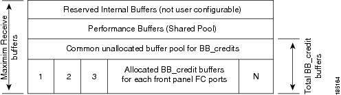
Figure 22-1 shows the allocation of BB_credit buffers on linecards (24-port and 48-port line cards).
Note
Figure 22-1 Receive Buffers for Fibre Channel Ports in a Global Buffer Pool
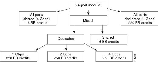
Figure 22-2 shows the default BB_credit buffer allocation model for 24-port 4-Gbps switching modules. The minimum BB_credits required to bring up a port is two buffers.
Figure 22-2 BB_Credit Buffer Allocation in 24-port 4-Gbps Switching Modules
Note
BB_Credit Buffers for Switching Modules
This section describes how buffer credits are allocated to Cisco MDS 9000 switching modules, and includes the following topics:
•
•
•
•
•
48-port 4-Gbps Fibre Channel Module BB_Credit Buffers
Table 22-5 lists the BB_credit buffer allocation for 48-port 4-Gbps Fibre Channel switching modules.
Table 22-5 48-Port 4-Gbps Switching Module BB_Credit Buffer Allocation Defaults
User configurable BB_credit buffers
6000
125
16
16
16
1 ISL = E port or TE port.
The following considerations apply to BB_credit buffers on 48-port 4-Gbps Fibre Channel switching modules:
•
•
•
Each port group on the 48-port 4-Gbps Fibre Channel switching module consists of 12 ports. The ports in shared rate mode have bandwidth oversubscription of 4:1 by default. However, some configurations of the shared ports in a port group can have maximum bandwidth oversubscription of 5:1 (considering that each port group has 12.8-Gbps bandwidth).
The following example configurations are supported by the 48-port 4-Gbps Fibre Channel switching modules:
•
•
11 ports with shared rate mode and 4-Gbps speed (5:1 oversubscription)•
11 ports with shared rate mode and 2-Gbps speed (2.5:1 oversubscription)•
10 ports with shared rate mode and 4-Gbps speed (5:1 oversubscription)•
10 ports with shared rate mode and 2-Gbps speed (2.5:1 oversubscription)•
•
four ports with shared rate mode and 1-Gbps speed plus
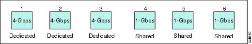
five ports put out-of-service (see Figure 22-3)Figure 22-3 Example Speed and Rate Configuration on a 48-Port 4-Gbps Switching Module
•
four ports with shared rate mode and 1-Gbps speed plus
two ports put out-of-service (see Figure 22-4)Figure 22-4 Example Speed and Rate Configuration on a 48-Port 4-Gbps Switching Module
24-port 4-Gbps Fibre Channel Module BB_Credit Buffers
Table 22-7 lists the BB_credit buffer allocation for 24-port 4-Gbps Fibre Channel switching modules.
Table 22-6 24 Port 4-Gbps Switching Module BB_Credit Buffer Allocation Defaults
User configurable BB_credit buffers
6000
250
16
16
16
1 ISL = E port or TE port.
The following considerations apply to BB_credit buffers on 24-port 4-Gbps Fibre Channel switching modules:
•
•
•
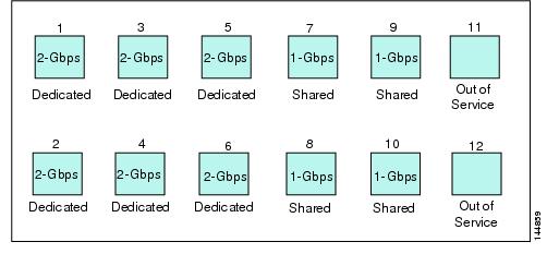
Each port group on the 24-port 4-Gbps Fibre Channel switching module consists of six ports. The ports in shared rate mode have bandwidth oversubscription of 2:1 by default. However, some configurations of the shared ports in a port group can have maximum bandwidth oversubscription of 4:1 (considering that each port group has 12.8-Gbps bandwidth). The following example configurations are supported by the 24-port 4-Gbps Fibre Channel switching modules:
•
•
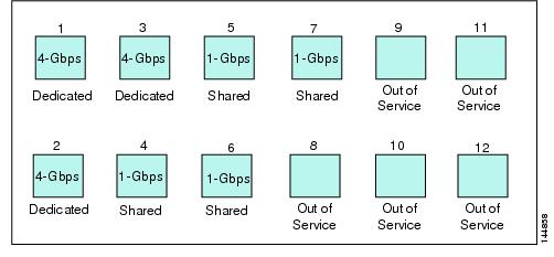
four ports with shared rate mode and 4-Gbps speed (with 4:1 oversubscription)•
three ports with dedicated rate mode and 2-Gbps speed plus
two ports with shared rate mode and 4-Gbps speed (4:1 oversubscription)•
•
three ports with shared rate mode and 1-Gbps speed (see Figure 22-5)Figure 22-5 Example Speed and Rate Configuration on a 24-Port 4-Gbps Switching Module
18-Port Fibre Channel/4-Port GigabitEthernet Multiservice Module BB_Credit Buffers
Table 22-7 lists the BB_credit buffer allocation for 18-port 4-Gbps multiservice modules.
Table 22-7 18-Port 4-Gbps Multiservice Module BB_Credit Buffer Allocation Defaults
User configurable BB_credit buffers
4509
250
16
16
16
1 ISL = E port or TE port.
The following considerations apply to BB_credit buffers on18-port 4-Gbps Fibre Channel switching modules:
•
•
•
12-Port 4-Gbps Switching Module BB_Credit Buffers
Table 22-8 lists the BB_credit buffer allocation for 12-port 4-Gbps switching modules.
Table 22-8 12-Port 4-Gbps Switching Module BB_Credit Buffer Allocation Defaults
User configurable BB_credit buffers
5488
250
16
Performance buffers
512 (shared)
145
12
1 ISL = E port or TE port.
The following considerations apply to BB_credit buffers on 12-port 4-Gbps switching modules:
•
•
•
•
Note
Note
4-Port 10-Gbps Switching Module BB_Credit Buffers
Table 22-9 lists the BB_credit buffer allocation for 4-port 10-Gbps switching modules.
Table 22-9 4-port 10-Gbps Switching Module BB_Credit Buffer Allocation Defaults
User configurable BB_credit buffers
5488
250
16
Performance buffers
512 (shared)
145
12
1 ISL = E port or TE port.
2 Ports on the 4-port 10-Gbps cannot operate in FL port mode.
Note
The following considerations apply to BB_credit buffers on 4-port 10-Gbps switching modules:
•
•
•
•
Note
BB_Credit Buffers for Fabric Switches
This section describes how buffer credits are allocated to Cisco MDS 9000 Fabric switches, and includes the following topics:
•
•
•
Cisco MDS 9134 Fabric Switch BB_Credit Buffers
Table 22-10 lists the BB_credit buffer allocation for 32-port 4-Gbps Fibre Channel switches.
Table 22-10 32-Port 4-Gbps Switching Module BB_Credit Buffer Allocation Defaults
User configurable BB_credit buffers
64
64
64
1 ISL = E port or TE port.
The following considerations apply to BB_credit buffers on 32-port 4-Gbps switches:
•
•
Cisco MDS 9124 Fabric Switch BB_Credit Buffers
Table 22-11 lists the BB_credit buffer allocation for 24-port 4-Gbps Fibre Channel switches.
Table 22-11 24-Port 4-Gbps Switching Module BB_Credit Buffer Allocation Defaults
User configurable BB_credit buffers
64
16
16
1 ISL = E port or TE port.
Cisco MDS 9222i Multiservice Modular Switch BB_Credit Buffers
Table 22-12 lists the BB_credit buffer allocation for 18-port 4-Gbps Multiservice Modular switches.
Table 22-12 18-Port 4-Gbps Switching Module BB_Credit Buffer Allocation Defaults
User configurable BB_credit buffers
4509
250
16
1 ISL = E port or TE port.
Extended BB_Credits
Note
To facilitate BB_credits for long haul links, the extended BB_credits feature allows the user to configure the receive buffers above the maximum value on all Generation 2 switching modules (see the "Buffer Credit Allocation" section). When necessary, you can reduce the buffers on one port and assign them to another port, exceeding the default maximum. The minimum extended BB_credits per port is 256 and the maximum is 4095.
In general, the user can configure any port in a port group to dedicated mode. To do this, you must first release the buffers from the other ports before configuring larger extended BB_credits for a port.
Note
All ports on the Generation 2 switching modules support extended BB_credits. There are no limitations for how many extended BB_credits you can assign to a port (except for the maximum and minimum limits). If necessary, you can take interfaces out of service to make more extended BB_credits available to other ports.
About Combining Generation 1 and Generation 2 Switching Modules
You can combine Generation 1 and Generation 2 switching modules, with either Supervisor-1 modules or Supervisor-2 modules. However, combining switching modules and supervisor modules has the following port index limitations:
•
•
•
Port Indexes
Cisco MDS 9000 switches allocate index identifiers for the ports on the modules. These port indexes cannot be configured. You can combine Generation 1 and Generation 2 switching modules, with either Supervisor-1 modules or Supervisor-2 modules. However, combining switching modules and supervisor modules has the following port index limitations:
•
•
•
Note
Generation 1 switching modules have specific numbering requirements. If these requirements are not met, the module does not power up. The port index numbering requirements include the following:
•
•
Note
The allowed mix of Generation 1 and Generation 2 switching modules in a chassis is determined at run-time, either when booting up the switch or when installing the modules. In some cases, the sequence in which switching modules are inserted into the chassis determines if one or more modules is powered up. When a module does not power up because of a resource limitation, you can . see the reason by viewing the module information in the Information pane.
For information on recovering a module powered-down because port indexes are not available, refer to the Cisco MDS 9000 Family Troubleshooting Guide, Release 3.x.
PortChannels
PortChannels have the following restrictions:
•
•
•
Note
When configuring PortChannels on switches with both Generation 1 and Generation 2 switching modules, configure the PortChannel and Generation 2 switching modules interfaces to auto with a maximum of 2 Gbps or configure the Generation 1 switching modules followed by the Generation 2 switching modules.
Note
Table 22-14 describes the results of adding a member to a PortChannel for various configurations.
Table 22-14 PortChannel Configuration and Addition Results
No members
Any
Any
Generation 1 or Generation 2
Force
Pass
Auto
Auto
Generation 1 or Generation 2
Normal or force
Pass
Auto max 2000
Auto
Generation 1
Normal or force
Pass
Auto max 2000
Auto
Generation 2
Normal
Fail
Force
Pass
Auto
Auto max 2000
Generation 2
Normal
Fail
Force
Pass or fail1
Generation 1 interfaces
Auto
Auto
Generation 2
Normal
Fail
Force
Pass
Auto max 2000
Auto
Generation 1
Normal or force
Pass
Auto max 2000
Auto
Generation 2
Normal
Fail
Force
Pass or fail1
Generation 2 interfaces
Auto
Auto
Generation 1
Normal or force
Fail
Auto max 2000
Auto
Generation 1
Normal or force
Pass
Auto max 2000
Auto
Generation 2
Normal
Fail
Force
Pass
Auto
Auto max 2000
Generation 2
Normal
Fail
Force
Pass
1 Is resources not available.
Configuring Generation 2 Module Interface Shared Resources
This section describes how to configure Generation 2 module interface shared resources and contains the following sections:
•
•
•
•
•
•
•
Configuration Guidelines for 48-Port and 24-Port 4-Gbps Fibre Channel Switching Modules
The 48-port and 24-port 4-Gbps Fibre Channel switching modules support the following features:
•
•
•
•
Migrating from Shared Mode to Dedicated Mode
To configure 48-port and 24-port 4-Gbps Fibre Channel switching modules when starting with the default configuration or when migrating from shared rate mode to dedicated rate mode, follow these guidelines:
1.
See the "Taking Interfaces Out of Service" section.
2.
See the "Configuring Port Speed" section.
3.
See the "Configuring Rate Mode" section.
4.
See the "About Interface Modes" section on page 20-4.
Note
5.
See the "Extended BB_Credits" section.
Migrating from Dedicated Mode to Shared Mode
To configure 48-port and 24-port 4-Gbps Fibre Channel switching modules migrating from dedicated rate mode to shared rate mode, follow these guidelines:
1.
See the "Taking Interfaces Out of Service" section.
2.
See the "BB_Credit Buffers for Switching Modules" section, "BB_Credit Buffers for Fabric Switches" section, and the "Extended BB_Credits" section.
3.
See the "About Interface Modes" section on page 20-4.
Note
4.
See the "Configuring Rate Mode" section.
5.
See the "Configuring Port Speed" section.
Configuration Guidelines for 12-Port 4-Gbps Switching Module Interfaces
The 12-port 4-Gbps switching modules support the following features:
•
•
•
•
•
To configure 4-port 10-Gbps switching modules when starting with the default configuration, follow these guidelines:
1.
See the "Configuring Port Speed" section.
2.
See the "About Interface Modes" section on page 20-4.
3.
See the "BB_Credit Buffers for Switching Modules" section, "BB_Credit Buffers for Fabric Switches" section, and the "Extended BB_Credits" section.
Note
Configuration Guidelines for 4-Port 10-Gbps Switching Module Interfaces
The 4-port 10-Gbps switching modules support the following features:
•
•
•
•
•
Use the following guidelines to configure 4-port 10-Gbps switching modules when starting with the default configuration:
1.
See the "About Interface Modes" section on page 20-4.
2.
See the "BB_Credit Buffers for Switching Modules" section, "BB_Credit Buffers for Fabric Switches" section, and the "Extended BB_Credits" section.
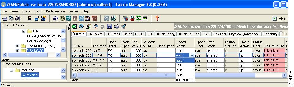
Configuring Port Speed
The port speed on an interface, combined with the rate mode, determines the amount of shared resources available to the ports in the port group on a 48-port or 24-port 4-Gbps Fibre Channel switching module. Especially in the case of dedicated rate mode, the port group resources are reserved even though the bandwidth is not used. For example, if an interface is configured for autosensing (auto) and dedicated rate mode, then 4 Gbps of bandwidth is reserved even though the maximum operating speed is 2 Gbps. For the same interface, if autosensing with a maximum speed of 2 Gbps (auto max 2000) is configured, then only 2 Gbps of bandwidth is reserved and the unused 2 Gbps is shared with the other interface in the port group.
Caution
Note
To configure dedicated bandwidth on an interface using Fabric Manager, follow these steps
Step 1
Step 2
You see the FC Physical > General tab in the Interfaces pane.
Step 3
Step 4
Figure 22-6 Speed Admin column in Port Configuration
The auto parameter enables autosensing on the interface. The autoMax2G parameter enables autosensing on the interface with a maximum speed of 2 Gbps.
Note
Step 5
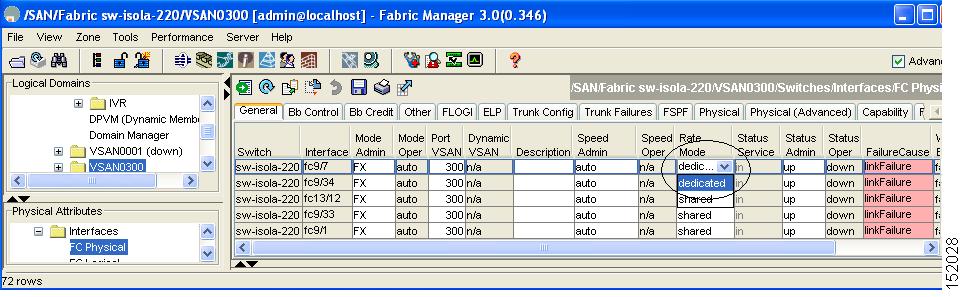
Configuring Rate Mode
To configure the rate mode (dedicated or shared) on an interface on a 48-port or 24-port 4-Gbps Fibre Channel switching module using Fabric Manager, follow these steps:
Step 1
Step 2
You see the FC Physical > General tab in the Interfaces pane.
Step 3
Step 4
Figure 22-7 Rate Mode Port Configuration
Step 5
Caution
Configuring Oversubscription Ratio Restrictions
The 48-port and 24-port 4-Gbps Fibre Channel switching modules support oversubscription on switches with shared rate mode configurations. Table 22-15 describes the bandwidth allocation for oversubscribed interfaces configured in shared mode.
By default, all 48-port and 24-port 4-Gbps Fibre Channel switching modules have restrictions on oversubscription ratios enabled.
As of Cisco SAN-OS Release 3.1(1) and later, you can disable restrictions on oversubscription ratios. All ports in 48-port and 24-port modules can be configured to operate at 4 Gbps in shared mode-even if other ports in the port group are configured in dedicated mode-regardless of available bandwidth. However, when oversubscription ratio restrictions are enabled you may not have all shared ports operating at 4 Gbps. For example, oversubscription ratios are enabled, and you have configured three 4 Gbps dedicated ports in one port group, no other ports in the same port group can be configured to operate at 4 Gbps.
For dedicated ports, oversubscription ratio restrictions do not apply to the shared pool in port groups. So if oversubscription ratio restrictions are disabled, and you've configured three 4 Gbps dedicated ports in one port group, then you can configure all other ports in the same port group to operate at a shared rate of 4 Gbps.
When disabling restrictions on oversubscription ratios, all ports in shared mode on 48-port and 24-port 4-Gbps Fibre Channel switching modules must be shut down. When applying restrictions on oversubscription ratios, you must take shared ports out of service.
Note
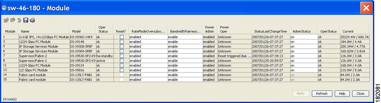
Disabling Restrictions on Oversubscription Ratios
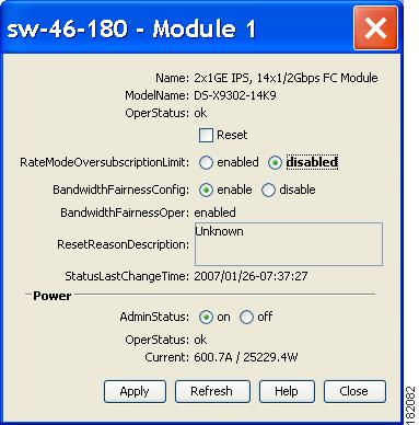
Before disabling restrictions on oversubscription ratios, ensure that you have explicitly shut down shared ports. To disable restrictions on oversubscription ratios on multiple 48-port or 24-port 4-Gbps Fibre Channel switching modules using Device Manager, follow these steps:
Step 1
You see the Module dialog box as shown in Figure 22-8.
Figure 22-8 Module Dialog Box
Caution
Step 2
Step 3
To disable restrictions on oversubscription ratios on a single 48-port or 24-port 4-Gbps Fibre Channel switching module using Device Manager, follow these steps:
Step 1
You see the Module dialog box as shown in Figure 22-9.
Figure 22-9 Module Dialog Box
Step 2
Step 3
Enabling Restrictions on Oversubscription Ratios
Caution
Before enabling restrictions on oversubscription ratios, ensure that you have explicitly configured shared ports to out-of-service mode. To enable restrictions on oversubscription ratios on multiple 48-port or 24-port 4-Gbps Fibre Channel switching modules using Device Manager, follow these steps:
Step 1
You see the Module dialog box as shown in Figure 22-8.
Step 2
Step 3
To enable restrictions on oversubscription ratios on a single 48-port or 24-port 4-Gbps Fibre Channel switching module using Device Manager, follow these steps:
Step 1
You see the Module dialog box as shown in Figure 22-9.
Step 2
Step 3
Configuring Bandwidth Fairness
As of Cisco SAN-OS Release 3.1(2) and later, all 48-port and 24-port 4-Gbps Fibre Channel switching modules, as well as 18-port Fibre Channel/4-port GigabitEthernet Multiservice modules, have bandwidth fairness enabled by default, which improves fairness of bandwidth allocation among all ports and provides better throughput average to individual data streams. Bandwidth fairness can be configured per module.
Caution
Note
Enabling Bandwidth Fairness
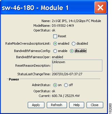
To enable bandwidth fairness on multiple 48-port or 24-port 4-Gbps Fibre Channel switching modules using Device Manager, follow these steps:
Step 1
You see the Module dialog box as shown in Figure 22-10.
Figure 22-10 Module Dialog Box
Step 2
Step 3
To enable bandwidth fairness on a single 48-port or 24-port 4-Gbps Fibre Channel switching module using Device Manager, follow these steps:
Step 1
You see the Module dialog box as shown in Figure 22-11.
Figure 22-11 Module Dialog Box
Step 2
Step 3
Disabling Bandwidth Fairness
Note
To disable bandwidth fairness on multiple 48-port or 24-port 4-Gbps Fibre Channnel switching modules using Device Manager, follow these steps:
Step 1
You see the Module dialog box as shown in Figure 22-10.
Step 2
Step 3
To disable bandwidth fairness on a single 48-port or 24-port 4-Gbps Fibre Channel switching module using Device Manager, follow these steps:
Step 1
You see the Module dialog box as shown in Figure 22-11.
Step 2
Step 3
Upgrade or Downgrade Scenario
When you are upgrading from a release earlier than Cisco SAN-OS Release 3.1(2), all modules operate with bandwidth fairness disabled until the next module reload. After the upgrade, any new module that is inserted has bandwidth fairness enabled.
When you are downgrading to a release earlier than Cisco SAN-OS Release 3.1(2), all modules keep operating in the same bandwidth fairness configuration prior to the downgrade. After the downgrade, any new module that is inserted has bandwidth fairness disabled.
Taking Interfaces Out of Service
You can take interfaces out of service on Generation 2 switching modules. When an interface is out of service, all the shared resources for the interface are released as well as the configuration associated with those resources.
Note
Caution
Note
To take an interface out of service using Fabric Manager, follow these steps:
Step 1
Step 2
You see the FC Physical > General tab in the Information pane.
Step 3
Step 4
Step 5
Step 6
Releasing Shared Resources in a Port Group
When you want to reconfigure the interfaces in a port group on a Generation 2 module, you can return the port group to the default configuration to avoid problems with allocating shared resources.
Note
Caution
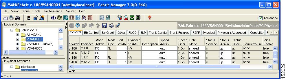
To release the shared resources for a port group using Fabric Manager, follow these steps:
Step 1
Step 2
You see the FC Physical > General tab in the Information pane.
Step 3
Step 4
Figure 22-12 Status Service Column for FC Physical
Step 5
Step 6
Step 7
Step 8
Displaying SFP Diagnostic Information
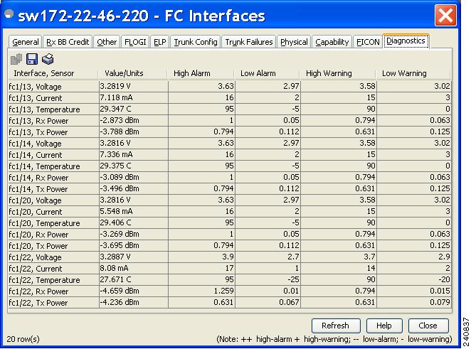
To view diagnostic information for multiple ports using Device Manager, follow these steps:
Step 1
Step 2
You see the FC Interfaces dialog box shown in Figure 22-13.
Figure 22-13 FC Interfaces Dialog Box
Step 3
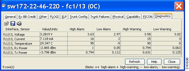
To view diagnostic information for a single port using Device Manager, follow these steps:
Step 1
You see the port licensing options for the selected port shown in Figure 22-14.
Figure 22-14 Diagnostics Tab for Selected Port
Step 2
Default Settings
Table 22-16 lists the default settings for Generation 2 interface parameters.
Table 22-16 Default Generation 2 Interface Parameters
Speed mode
auto1
auto1
auto1
auto2
Rate mode
shared
shared
dedicated
dedicated
Port mode
Fx
Fx
auto3
auto4
BB_credit buffers
16
16
250
250
Performance buffers
-
-
1455
1455
1 Auto speed mode on the 4-Gbps switching modules negotiates 1, 2, and 4 Gbps.
2 The 4-port 10-Gbps switching module only supports 10-Gbps traffic.
3 Auto port mode on the 12-port 4-Gbps switching module interfaces can operate in E port mode, TE port mode, and Fx port mode.
4 Auto port mode on the 4-port 10-Gbps switching module interfaces can operate in E port mode, TE port mode, and F port mode.
5 Performance buffers are shared among all ports on the module.