-
Cisco MDS 9000 Family Fabric Manager Configuration Guide, Release 3.x
-
Index
-
New and Changed Information
-
Preface
- Getting Started
- Installation and Switch Management
- Switch Configuration
-
Fabric Configuration
-
Configuring and Managing VSANs
-
SAN Device Virtualization
-
Creating Dynamic VSANs
-
Configuring Inter-VSAN Routing
-
Distributing Device Alias Services
-
Configuring and Managing Zones
-
Configuring Fibre Channel Routing Services and Protocols
-
Dense Wavelength Division Multiplexing
-
Managing FLOGI, Name Server, FDMI, and RSCN Databases
-
Discovering SCSI Targets
-
Configuring FICON
-
Advanced Features and Concepts
-
-
Security
-
Configuring FIPS
-
Configuring Users and Common Roles
-
Configuring SNMP
-
Configuring RADIUS and TACACS+
-
Configuring IPv4 Access Control Lists
-
Configuring Certificate Authorities and Digital Certificates
-
Configuring IPsec Network Security
-
Configuring FC-SP and DHCHAP
-
Configuring Port Security
-
Configuring Fabric Binding
-
- IP Services
- Intelligent Storage Services
- Network and Switch Monitoring
- Traffic Management
- Troubleshooting
-
Launching Fabric Manager in Cisco SAN-OS Releases Prior to 3.2(1)
-
Cisco Fabric Manager Unsupported Feature List
-
Interface Nonoperational Reason Codes
-
Managing Cisco FabricWare
-
Configuration Limits for Cisco MDS SAN-OS Release 3.1(x) and 3.2(x)
-
 Feedback
Table Of Contents
Displaying Switch Hardware Inventory
,Running the CompactFlash Report
Displaying the Switch Serial Number
Displaying Power Usage Information
Power Supply Configuration Modes
Power Supply Configuration Guidelines
Operational Considerations When Removing Crossbars
Graceful Shutdown of a Crossbar
Backward Compatibility for Generation 1 Modules in Cisco MDS 9513 Directors
Managing System Hardware
This chapter provides details on how to manage system hardware other than services and switching modules and how to monitor the health of the switch. It includes the following sections:
•
Displaying Switch Hardware Inventory
•
•
•
•
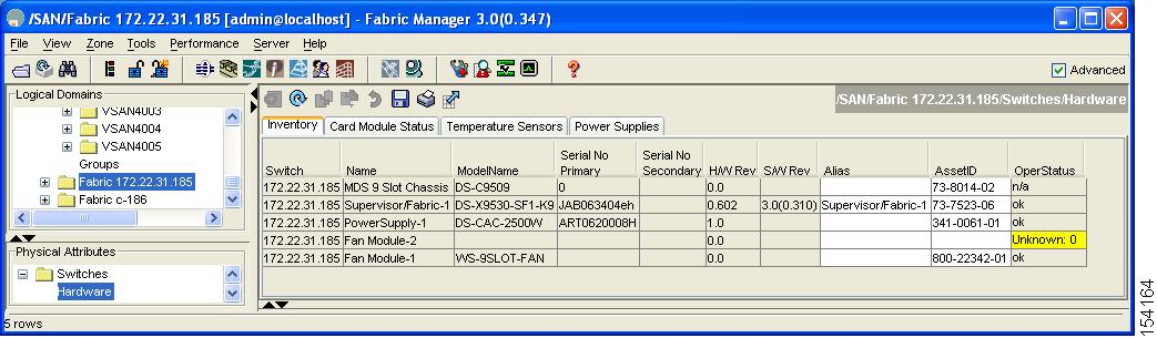
Displaying Switch Hardware Inventory
To view information on the field replaceable units (FRUs) in the switch, including product IDs and serial numbers, follow these steps:
Step 1
You see a list like the one shown in Figure 18-1.
Figure 18-1 Fabric Manager Hardware Inventory
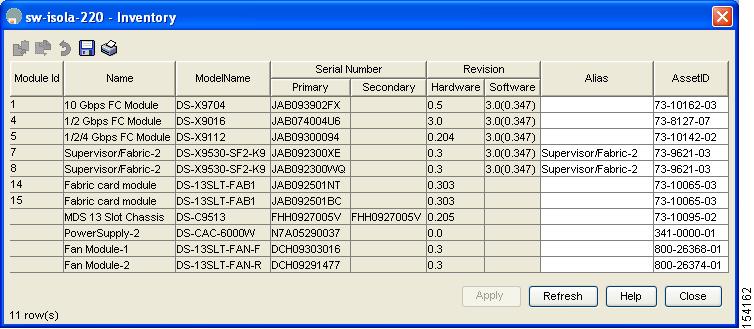
Step 2
You see a list like the one shown in Figure 18-2.
Figure 18-2 Device Manager Hardware Inventory
You see system attributes for multiple switches in Figure 18-1 and Figure 18-2. To see attributes for a single switch in Device Manager, double click the graphic of the switch in the main screen.
Note
,Running the CompactFlash Report
In Cisco SAN-OS Release 3.1(2), you can run the CompactFlash Check Utility to automatically scan your fabric and generate a report that shows the status of CompactFlash on the following modules:
•
•
•
•
•
•
The CompactFlash report can be used on switches running Cisco SAN-OS Release 2.x or later. Before running the CompactFlash report, you must complete the following tasks:
•
•
•
Step 1
Step 2
To run the CompactFlash report using Fabric Manager, follow these steps:
Step 1
Note
Step 2
Step 3
Step 4
Note
Step 5
Step 6
Step 7
Displaying the Switch Serial Number
The serial number of your Cisco MDS 9000 Family switch can be obtained by looking at the serial number label on the back of the switch (next to the power supply) or from Fabric Manager by selecting that switch in the Logical Domains pane, then expanding Switches and selecting Hardware in the Physical Attributes pane in Fabric Manager. The Serial No Primary column in the Information pane shows the serial number.
Displaying Power Usage Information
Use Fabric Manager to display power usage. Select a switch in the Logical Domains pane, expand Switches and select Hardware in the Physical Attributes pane, then click the Power Supplies tab in the Information pane to display actual power usage information for the entire switch. See the first example under Power Supply Configuration Modes.
Note
Power Supply Configuration Modes
Switches in the MDS 9000 Family have two redundant power supply slots. The power supplies can be configured in either redundant or combined mode.
•
•
Note
To configure the power supply mode, follow these steps:
Step 1
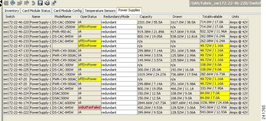
You see the power supply information screen shown in Figure 18-3.
Low TotalAvailable (< 200.0W) values for non-2-slot chassis are highlighted in yellow, as inserting a new card into the switch requires power around 180W.
Figure 18-3 Power Supply Information in Fabric Manager
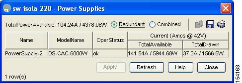
Step 2
You see the screen in Figure 18-4.
Figure 18-4 Power Supply Information in Device Manager
Step 3
Step 4
Note
Power Supply Configuration Guidelines
Follow these guidelines when configuring power supplies:
1.
a.
For example, suppose you have the following usage figures configured:Power supply 1 = 2500 W
Additional power supply 2 = not used
Current usage = 2000 W
Current capacity = 2500 WThen the following three scenarios differ as specified (see Table 18-1):
Scenario 1: If 1800 W is added as power supply 2, then power supply 2 is shut down.
Reason: 1800 W is less than the usage of 2000 W.Scenario 2: If 2200 W is added as power supply 2, then the current capacity decreases to 2200 W.
Reason: 2200 W is the lesser of the two power supplies.Scenario 3: If 3000 W is added as power supply 2, then the current capacity value remains at 2500 W.
Reason: 2500 W is the lesser of the two power supplies.
Table 18-1 Redundant Mode Power Supply Scenarios
(W)1
2500
2000
1800
2500
Power supply 2 is shut down.
2
2500
2000
2200
2200
Capacity becomes 2200 W.
3
2500
2000
3300
2500
Capacity remains the same.
1 W = Watts
b.
For example, suppose you have the following usage figures configured:
Power supply 1 = 2500 W
Additional Power supply 2 = not used
Current Usage = 2000 W
Current capacity = 2500 WThen, the following three scenarios differ as specified (see Table 18-2):
Scenario 1: If 1800 W is added as power supply 2, then the capacity increases to 3600 W.
Reason: 3600 W is twice the minimum (1800 W).Scenario 2: If 2200 W is added as power supply 2, then the current capacity increases to 4400 W.
Reason:4400 W is twice the minimum (2200 W).Scenario 3: If 3000 W is added as power supply 2, then the current capacity increases to 5000 W.
Reason: 5000 W is twice the minimum (2500 W).
Table 18-2 Combined Mode Power Supply Scenarios
(W)
(W)1
2500
2000
1800
3600
Power is never shut down. The new capacity is changed.
2
2500
2000
2200
4400
3
2500
2000
3300
5000
1 W = Watts
2.
Scenario 1: You have the following usage figures configured:
Power supply 1 = 2500 W
Additional Power supply 2 = 1800 W
Current Usage = 2000 W
Current mode = combined mode (so current capacity is 3600 W)You decide to change the switch to redundant mode. Then power supply 2 is shut down.
Reason: 1800 W is the lesser of the two power supplies and it is less than the system usage.
Scenario 2: You have the following usage figures configured:
Power supply 1 = 2500 W
Additional Power supply 2 = 2200 W
Current Usage = 2000 W
Current mode = combined mode (so current capacity is 4400 W).You decide to change the switch to redundant mode. Then the current capacity decreases to 2200 W.
Reason: 2200 W is the lesser of the two power supplies.
Scenario 3: You have the following usage figures configured:
Power supply 1 = 2500 W
Additional Power supply 2 = 1800 W
Current Usage = 3000 W
Current mode = combined mode (so current capacity is 3600 W).You decide to change the switch to redundant mode. Then the current capacity decreases to 2500 W and the configuration is rejected.
Reason: 2500 W is less than the system usage (3000 W).
Table 18-3 Combined Mode Power Supply Scenarios
1
2500
combined
2000
1800
N/A
3600
This is the existing configuration.
2500
N/A
2000
1800
redundant
2500
Power supply 2 is shut down
2
2500
combined
2000
2200
N/A
4400
This is the existing configuration.
2500
N/A
2000
2200
redundant
2200
The new capacity is changed.
3
2500
combined
3000
1800
N/A
3600
This is the existing configuration.
2500
N/A
3000
1800
redundant
N/A
Rejected, so the mode reverts to combined mode.
1 W = Watts
About Crossbar Management
Cisco MDS SAN-OS Release 3.0(1) and later supports two types of hardware for the Cisco MDS 9500 Series Directors: Generation 1 and Generation 2.
Generation 1 consists of all hardware supported by Cisco SAN-OS prior to Release 3.0(1), including the following:
•
•
•
•
•
•
•
•
Generation 2 consists of all new hardware supported by Cisco SAN-OS Release 3.0(1) and later, including the following:
•
•
•
•
•
•
The Cisco MDS 9500 Series Directors running Cisco MDS SAN-OS 3.0(1) or later support the following types of crossbars:
•
•
Operational Considerations When Removing Crossbars
You can mix and match Generation 1 and Generation 2 hardware on the Cisco MDS 9500 Series Directors running Cisco MDS SAN-OS 3.0(1) or later without compromising the integrity and availability of your SANs based on Cisco MDS 9500 Series Directors.
To realize these benefits, you must consider the following operational requirements when removing crossbars for maintenance activities:
•
•
Graceful Shutdown of a Crossbar
You must perform a graceful shutdown of a crossbar (integrated or external) before removing it from the MDS 9500 Series Director.
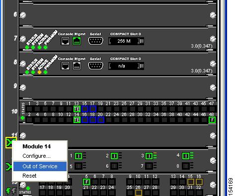
To perform a graceful shutdown of external crossbar switching modules in a Cisco MDS 9513 Director using Device Manager, follow these steps:
Step 1
You see the context menu for the supervisor module.
Figure 18-5 Shutting Down a Crossbar
Step 2
Note
Caution
To perform a graceful shutdown of integrated crossbars on the supervisor module in a Cisco MDS 9509 or 9506 Director using Device Manager, follow these steps:
Step 1
You see the context menu for that module.
Step 2
Note
Caution
Backward Compatibility for Generation 1 Modules in Cisco MDS 9513 Directors
To provide backward compatibility for a Generation 1 module in a Cisco MDS 9513 chassis, the active and backup Supervisor-2 modules are associated to a specific crossbar module. The Supervisor-2 module in slot 7 is associated with crossbar module 1 and Supervisor-2 module in slot 8 is associated with crossbar module 2. You must plan for the following operational considerations before removing crossbar modules:
•
–
–
–
•
Note
About Module Temperature
Built-in, automatic sensors are provided in all switches in the Cisco MDS 9000 Family to monitor your switch at all times.
Each module (switching and supervisor) has four sensors: 1 (outlet sensor), 2 (intake sensor), 3 (onboard sensor), and 4 (onboard sensor). Each sensor has two thresholds (in degrees Celsius): minor and major.
Note
•
–
–
–
•
–
System messages are displayed.
Call Home alerts are sent (if configured).
SNMP notifications are sent (if configured).
–
If the threshold is exceeded in a switching module, only that module is shut down.
If the threshold is exceeded in an active supervisor module with HA-standby or standby present, only that supervisor module is shut down and the standby supervisor module takes over.
If you do not have a standby supervisor module in your switch, you have an interval of 2 minutes to decrease the temperature. During this interval the software monitors the temperature every five (5) seconds and continuously sends system messages as configured.
Tip
Displaying Module Temperature
Expand Switches and then select Hardware in the Physical Attributes pane in Fabric Manager. Click the Temperature Sensors tab in the Information pane to display temperature sensors for each module (see the second example under Power Supply Configuration Modes).
About Fan Modules
Hot-swappable fan modules (fan trays) are provided in all switches in the Cisco MDS 9000 Family to manage airflow and cooling for the entire switch. Each fan module contains multiple fans to provide redundancy. The switch can continue functioning in the following situations:
•
•
Tip
The fan status is continuously monitored by the Cisco MDS SAN-OS software. In case of a fan failure, the following action is taken:
•
•
•
To display the fan module status, from Device Manager, choose Physical > Fans. The dialog box displays the fan status.
The possible Status field values for a fan module on the Cisco MDS 9500 Series switches are as follows:
•
•
•
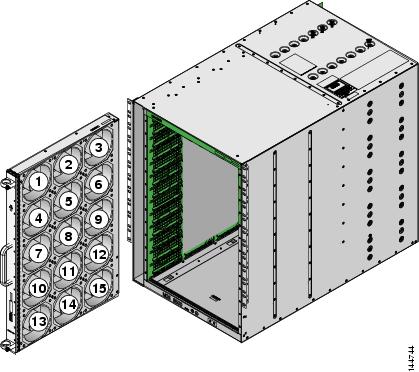
On the Cisco MDS 9513 Director, the front fan module has 15 fans. .
Figure 18-6 shows the numbering of the fans in the front fan module on the Cisco MDS 9513 Director.
Figure 18-6 Cisco MDS 9513 Front Fan Module Numbering
The rear fan module (DS-13SLT-FAN-R) on the Cisco MDS 9513 Director has only two fans. .
Default Settings
Table 18-4 lists the default hardware settings.