-
Cisco MDS 9000 Family Fabric Manager Configuration Guide, Release 3.x
-
Index
-
New and Changed Information
-
Preface
- Getting Started
- Installation and Switch Management
- Switch Configuration
-
Fabric Configuration
-
Configuring and Managing VSANs
-
SAN Device Virtualization
-
Creating Dynamic VSANs
-
Configuring Inter-VSAN Routing
-
Distributing Device Alias Services
-
Configuring and Managing Zones
-
Configuring Fibre Channel Routing Services and Protocols
-
Dense Wavelength Division Multiplexing
-
Managing FLOGI, Name Server, FDMI, and RSCN Databases
-
Discovering SCSI Targets
-
Configuring FICON
-
Advanced Features and Concepts
-
-
Security
-
Configuring FIPS
-
Configuring Users and Common Roles
-
Configuring SNMP
-
Configuring RADIUS and TACACS+
-
Configuring IPv4 Access Control Lists
-
Configuring Certificate Authorities and Digital Certificates
-
Configuring IPsec Network Security
-
Configuring FC-SP and DHCHAP
-
Configuring Port Security
-
Configuring Fabric Binding
-
- IP Services
- Intelligent Storage Services
- Network and Switch Monitoring
- Traffic Management
- Troubleshooting
-
Launching Fabric Manager in Cisco SAN-OS Releases Prior to 3.2(1)
-
Cisco Fabric Manager Unsupported Feature List
-
Interface Nonoperational Reason Codes
-
Managing Cisco FabricWare
-
Configuration Limits for Cisco MDS SAN-OS Release 3.1(x) and 3.2(x)
-
 Feedback
Table Of Contents
Configuring Inter-VSAN Routing
Fibre Channel Header Modifications
IVR NAT Requirements and Guidelines
Configuring IVR Using the IVR Zone Wizard
About IVR NAT and Auto Topology
Configuring IVR NAT and IVR Auto Topology
About IVR Without IVR NAT or Auto Topology
Manually Creating the IVR Topology
Activating a Manually Configured IVR Topology
Clearing the Configured IVR Topology
Migrating from IVR Auto Topology Mode to Manual Mode
Configuring IVR Virtual Domains
About Persistent FC IDs for IVR
Configuring Persistent FC IDs for IVR
Configuring IVR Logging Levels
Configuring IVR Zones and IVR Zone Sets
About Activating Zone Sets and Using the force Option
Recovering an IVR Full Zone Database
Recovering an IVR Full Topology
Configuring LUNs in IVR Zoning
Renaming IVR Zones and IVR Zone Sets
Clearing the IVR Zone Database
Configuring IVR Using Read-Only Zoning
System Image Downgrading Considerations
Resolving Database Merge Failures
Configuring Inter-VSAN Routing
This chapter explains the Inter-VSAN routing (IVR) feature and provides details on sharing resources across VSANs using IVR management interfaces provided in the switch.
This chapter includes the following sections:
Inter-VSAN Routing
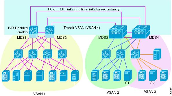
Virtual SANs (VSANs) improve storage area network (SAN) scalability, availability, and security by allowing multiple Fibre Channel SANs to share a common physical infrastructure of switches and ISLs. These benefits are derived from the separation of Fibre Channel services in each VSAN and isolation of traffic between VSANs. Data traffic isolation between the VSANs also inherently prevents sharing of resources attached to a VSAN, such as robotic tape libraries. Using IVR, you can access resources across VSANs without compromising other VSAN benefits.
This section includes the following topics:
•
Fibre Channel Header Modifications
About IVR
Note
Data traffic is transported between specific initiators and targets on different VSANs without merging VSANs into a single logical fabric. Fibre Channel control traffic does not flow between VSANs, nor can initiators access any resource across VSANs other than the designated ones. Valuable resources such as tape libraries are easily shared across VSANs without compromise.
IVR is in compliance with Fibre Channel standards and incorporates third-party switches, however, IVR-enabled VSANs may have to be configured in one of the interop modes.
IVR is not limited to VSANs present on a common switch. Routes that traverse one or more VSANs across multiple switches can be established, if necessary, to establish proper interconnections. IVR used in conjunction with FCIP provides more efficient business continuity or disaster recovery solutions (see Figure 29-1).
Figure 29-1 Traffic Continuity Using IVR and FCIP
Note
IVR Features
IVR supports the following features:
•
•
•
•
•
•
IVR Terminology
The following IVR-related terms are used in this chapter.:
•
•
•
•
•
•
•
Note
•
Note
•
•
•
IVR Limits Summary
Table 29-1 summarizes the configuration limits for IVR. See Appendix 60, "Configuration Limits for Cisco MDS SAN-OS Release 3.1(x) and 3.2(x)," for a complete list of Cisco MDS SAN-OS feature configuration limits.
Fibre Channel Header Modifications
IVR works by virtualizing the remote end devices in the native VSAN using a virtual domain. When IVR is configured to link end devices in two disparate VSANs, the IVR border switches are responsible for modifying the Fibre Channel headers for all communication between the end devices. The sections of the Fibre Channel frame headers that are modified include:
•
•
•
When a frame goes from the initiator to the target, the Fibre Channel frame header is modified such that the initiator VSAN number is changed to the target VSAN number. If IVR Network Address Translation (NAT) is enabled, then the source and destination FCIDs are also translated at the edge border switch. If IVR NAT is not enabled, then you must configure unique domain IDs for all switches involved in the IVR path.
IVR NAT
Without Network Address Translation (NAT), IVR requires unique domain IDs for all switches in the fabric. You can enable IVR NAT to allow non-unique domain IDs. This feature simplifies the deployment of IVR in an existing fabric where non-unique domain IDs might be present.
To use IVR NAT, it must be enabled in all IVR-enabled switches in the fabric IVR configuration distribution . By default, IVR NAT and IVR configuration distribution are disabled in all switches in the Cisco MDS 9000 Family.
IVR NAT Requirements and Guidelines
Following are requirements and guidelines for using IVR NAT:
•
Note
•
•
IVR NAT allows you to set up IVR in a fabric without needing unique domain IDs on every switch in the IVR path. IVR NAT virtualizes the switches in other VSANs by using local VSAN for the destination IDs in the Fibre Channel headers. In some Extended Link Service message types, the destinations IDs are part of the payload. In these cases, IVR NAT replaces the actual destination ID with the virtualized destination ID. IVR NAT supports destination ID replacement in the Extended Link Service messages described in Table 29-2.
If you have a message that is not recognized by IVR NAT and contains the destination ID in the payload, you cannot use IVR with NAT in your topology. You can still use IVR with unique domain IDs.
IVR VSAN Topology
IVR uses a configured IVR VSAN topology to determine how to route traffic between the initiator and the target across the fabric. You can configure this IVR VSAN topology manually on an IVR-enabled switch and distribute the configuration using CFS in Cisco MDS SAN-OS Release 2.0(1b) or later. Alternately, in Cisco MDS SAN-OS Release 2.1(1a) or later, you can configure IVR topology in auto mode. Prior to Cisco MDS SAN-OS Release 2.0(1b), you need to manually copy the IVR VSAN topology to each switch in the fabric.
Auto mode automatically builds the IVR VSAN topology and maintains the topology database when fabric reconfigurations occur. Auto mode distributes the IVR VSAN topology to IVR-enabled switches using CFS.
Using auto mode, you no longer need to manually update the IVR VSAN topology when reconfigurations occur in your fabric. If a manually configured IVR topology database exists, auto mode initially uses that topology information. This reduces disruption in the network by gradually migrating from the user-specified topology database to the automatically learned topology database. User configured topology entries that are not part of the network are aged out in about three minutes. New entries that are not part of the user configured database are added as they are discovered in the network.
When auto IVR topology is turned on it starts with the previously active, if any, manual IVR topology. Auto topology then commences its discovery process, and may come up with new, alternate or better paths. If the traffic is switched to an alternate or better path, there may be temporary traffic disruptions that are normally associated with switching paths.
Note
Autonomous Fabric ID
The autonomous fabric ID (AFID) distinguishes segmented VSANS (that is, two VSANs that are logically and physically separate but have the same VSAN number). Cisco MDS SAN-OS supports AFIDs from 1 through 64. AFIDs are used in conjunction with auto mode to allow segmented VSANS in the IVR VSAN topology database. You can configure up to 64 AFIDs.
The AFID can be configured individually for each switch and list of VSANs, or the default AFID can be configured for each switch.
Note
IVR Interoperability
When using the IVR feature, all border switches in a given fabric must be Cisco MDS switches. However, other switches in the fabric may be non-MDS switches. For example, end devices that are members of the active IVR zone set may be connected to non-MDS switches. Non-MDS switches may also be present in the transit VSAN(s) or in the edge VSANs if one of the interop modes is enabled.
See the "Switch Interoperability" section on page 29-8.
About the IVR Zone Wizard
The IVR Zone Wizard simplifies the steps required to configure IVR zones in a fabric. The IVR Zone Wizard checks the following conditions and prompts you for any issues:
•
•
Configuring IVR Using the IVR Zone Wizard
To configure IVR and IVR zones using the IVR Zone Wizard in Fabric Manager, follow these steps:
Step 1
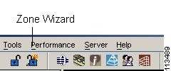
Figure 29-2 IVR Zone Wizard Icon
To migrate to IVR NAT mode click Yes, otherwise click No. You see the IVR Zone Wizard dialog box.
Step 2
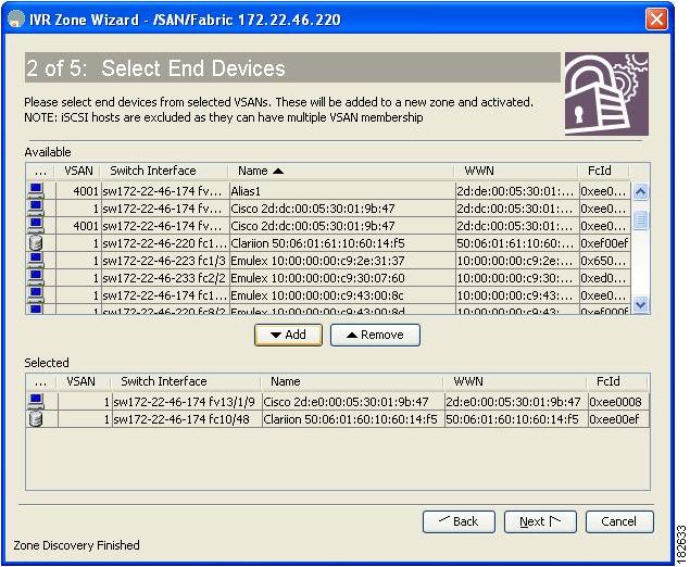
You see the Select End Devices dialog box shown in Figure 29-3.
Figure 29-3 Select End Devices Dialog Box
Step 3
Note
Step 4
Step 5
Step 6
Step 7
Step 8
Step 9
Step 10
You see the Save Configuration dialog box. You can save the configuration of the master switch to be copied to other IVR-enabled switches.
Step 11
Step 12
Note
Manual IVR Configuration
You can configure IVR using the IVR tables in the Information pane in Fabric Manager. Use these tables only if you are familiar with all IVR concepts. We recommend you configure IVR using the IVR Wizard.
Note
This section describes manually configuring IVR and includes the following topics:
•
•
•
•
•
•
•
•
•
•
•
About IVR NAT and Auto Topology
Before configuring an IVR SAN fabric to use IVR NAT and auto-topology, consider the following guidelines:
•
•
•
•
Note
Tip
Note
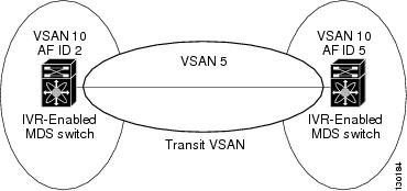
Transit VSAN Guidelines
Consider the following guidelines for transit VSANs:
•
–
–
•
•
Border Switch Guidelines
Before configuring border switches, consider the following guidelines:
•
•
•
•
The VSAN topology configuration updates automatically when a border switch is added or removed.
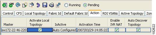
Configuring IVR NAT and IVR Auto Topology
To configure IVR in NAT mode and IVR topology in auto mode from Fabric Manager, follow these steps:
Step 1
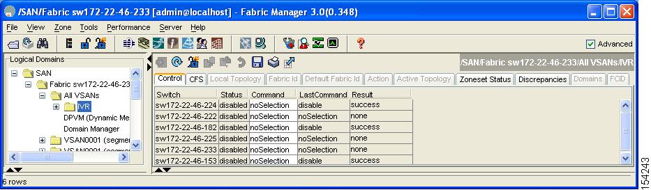
You see the inter-VSAN routing configuration in the Information pane shown in Figure 29-4.
Figure 29-4 IVR Routing Configuration Control Tab
Step 2
Step 3
Step 4
Step 5
Step 6
Step 7
About AFIDs
You can configure AFIDs individually for VSANs, or you can set the default AFIDs for all VSANs on a switch. If you configure an individual AFID for a subset of the VSANs on a switch that has a default AFID, that subset uses the configured AFID while all other VSANs on that switch use the default AFID. IVR supports a maximum of 64 AFIDs.
Note
Configuring Default AFIDs
To configure default AFIDs using Fabric Manager, follow these steps:
Step 1
You see the IVR configuration in the Information pane.
Step 2
Step 3
Step 4
Step 5
Step 6
Step 7
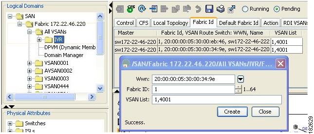
Configuring Individual AFIDs
To configure individual AFIDs using Fabric Manager, follow these steps:
Step 1
You see the IVR configuration in the Information pane.
Figure 29-5 Fabric ID Tab
Step 2
Step 3
Step 4
Step 5
Step 6
Step 7
Step 8
About IVR Without IVR NAT or Auto Topology
Before configuring an IVR SAN fabric without IVR in NAT mode or IVR topology in auto mode, consider the following guidelines:
•
–
–
•
•
Tip
Note
Domain ID Guidelines
Domain IDs must be unique across inter-connected VSANs when not using IVR NAT. To ensure unique domain IDs across inter-connected VSANs, consider these guidelines:
•
•
You can configure domain IDs using one of two options:
•
•
Note
Transit VSAN Guidelines
Before configuring transit VSANS, consider the following guidelines:
•
–
–
•
•
Border Switch Guidelines
Before configuring border switches, consider the following guidelines:
•
•
•
•
•
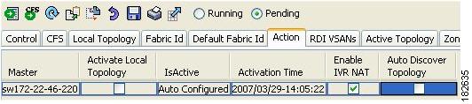
Configuring IVR Without NAT
To enable IVR in NAT mode from Fabric Manager, follow these steps:
Step 1
You see the IVR configuration in the Information pane.
Figure 29-6 Action Tab
Step 2
Step 3
Step 4
Manually Creating the IVR Topology
You must create the IVR topology in every IVR-enabled switch in the fabric if you have not configured IVR topology in auto mode. You can have up to 128 VSANs in an IVR topology. Specify the IVR topology using the following information:
•
•
•
Figure 29-7 Example IVR Topology with Non-Unique VSAN IDs Using AFIDs
Note
Note
Caution
To create the IVR topology using Fabric Manager, follow these steps:
Step 1
You see the IVR configuration in the Information pane.
Figure 29-8 Local Topology Tab
Step 2
Step 3
Step 4
Step 5
Step 6
Note
Tip
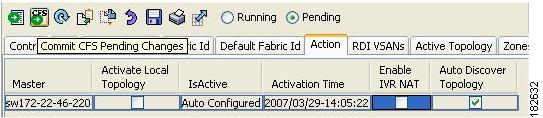
Activating a Manually Configured IVR Topology
After manually configuring the IVR topology , you must activate it.
Caution
To activate the manually configured IVR topology using Fabric Manager, follow these steps:
Step 1
You see the IVR configuration in the Information pane.
Figure 29-9 Action Tab
Step 2
Step 3
Step 4
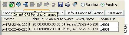
Clearing the Configured IVR Topology
You can only clear manually created IVR VSAN topology entries from the configured database.
To clear the IVR topology using Fabric Manager, follow these steps:
Step 1
Step 2
Step 3
Step 4
Step 5
Migrating from IVR Auto Topology Mode to Manual Mode
If you want to migrate the active IVR VSAN topology database from automatic mode to user-configured mode, first copy the active IVR VSAN topology database to the user-configured IVR VSAN topology database before switching modes.
To migrate from automatic mode to manual mode using Fabric Manager, follow these steps:
Step 1
You see the IVR configuration in the Information pane.
Figure 29-10 Action Tab
Step 2
Step 3
Step 4
Step 5
About IVR Virtual Domains
In a remote VSAN, the IVR application does not automatically add the virtual domain to the assigned domains list. Some switches (for example, the Cisco SN5428) do not query the remote name server until the remote domain appears in the assigned domains list in the fabric. In such cases, add the IVR virtual domains in a specific VSAN(s) to the assigned domains list in that VSAN. When adding IVR domains, all IVR virtual domains that are currently present in the fabric (and any virtual domain that is created in the future) will appear in the assigned domain list for that VSAN.
Tip
When you enable the IVR virtual domains, links may fail to come up due to overlapping virtual domain identifiers. If so, temporarily withdraw the overlapping virtual domain from that VSAN.
Note
Tip
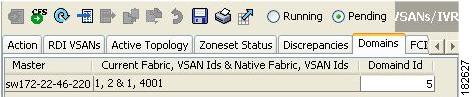
Configuring IVR Virtual Domains
To add IVR virtual domains using Fabric Manager, follow these steps:
Step 1
You see the IVR configuration in the Information pane.
Figure 29-11 Domains Tab
Step 2
Step 3
Step 4
Step 5
About Persistent FC IDs for IVR
You can configure persistent FC IDs for IVR. FC ID persistence across reboot improves IVR management by providing the following features:
•
•
The benefits of persistent FC IDs for IVR are as follows:
•
•
•
You can configure two types of database entries for persistent IVR FC IDs:
•
–
–
–
–
–
•
–
–
–
–
Note
Note
Note
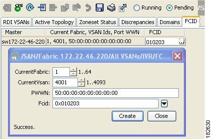
Configuring Persistent FC IDs for IVR
To configure persistent FC IDs for IVR using Fabric Manager, follow these steps:
Step 1
You see the IVR configuration in the Information pane.
Figure 29-12 FCID Tab
Step 2
Step 3
Step 4
Step 5
Step 6
Step 7
Step 8
Step 9
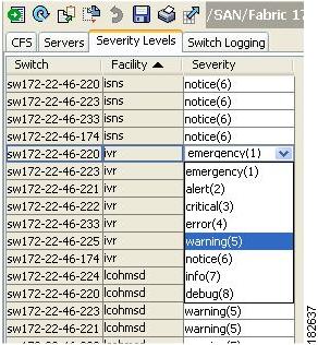
Configuring IVR Logging Levels
To configure the severity level for logging messages from the IVR feature using Fabric Manager, follow these steps:
Step 1
Step 2
Step 3
Step 4
Figure 29-13 Syslog Severity Drop-Down Menu
Tip
Step 5
IVR Zones and IVR Zone Sets
As part of the IVR configuration, you need to configure one or more IVR zone to enable cross-VSAN communication. To achieve this result, you must specify each IVR zone as a set of (pWWN, VSAN) entries. Like zones, several IVR zone sets can be configured to belong to an IVR zone. You can define several IVR zone sets and activate only one of the defined IVR zone sets.
Note
Caution
This section describes configuring IVR zones and IVR zone sets and includes the following topics:
•
•
•
•
•
•
•
•
•
•
About IVR Zones
Table 29-3 identifies the key differences between IVR zones and zones.
Automatic IVR Zone Creation
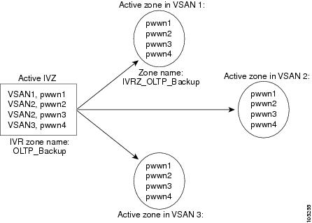
Figure 29-14 depicts an IVR zone consisting of four members. To allow pwwn1 to communicate with pwwn2, they must be in the same zone in VSAN 1, as well as in VSAN 2. If they are not in the same zone, then the hard-zoning ACL entries will prohibit pwwn1 from communicating with pwwn2.
A zone corresponding to each active IVR zone is automatically created in each edge VSAN specified in the active IVR zone. All pWWNs in the IVR zone are members of these zones in each VSAN.
Figure 29-14 Creating Zones Upon IVR Zone Activation
The zones are created automatically by the IVR process when an IVR zone set is activated. They are not stored in a full zone set database and are lost when the switch reboots or when a new zone set is activated. The IVR feature monitors these events and adds the zones corresponding to the active IVR zone set configuration when a new zone set is activated. Like zone sets, IVR zone sets are also activated nondisruptively.
Note
IVR zone and IVR zone set names are restricted to 64 alphanumeric characters.
Caution
Configuring IVR Zones and IVR Zone Sets
To create IVR zones and IVR zone sets using Fabric Manager, follow these steps:
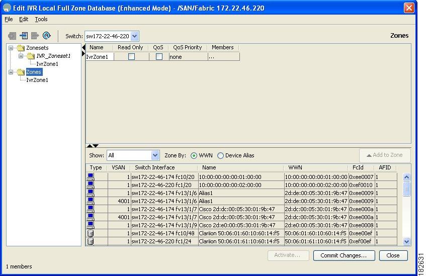
Step 1
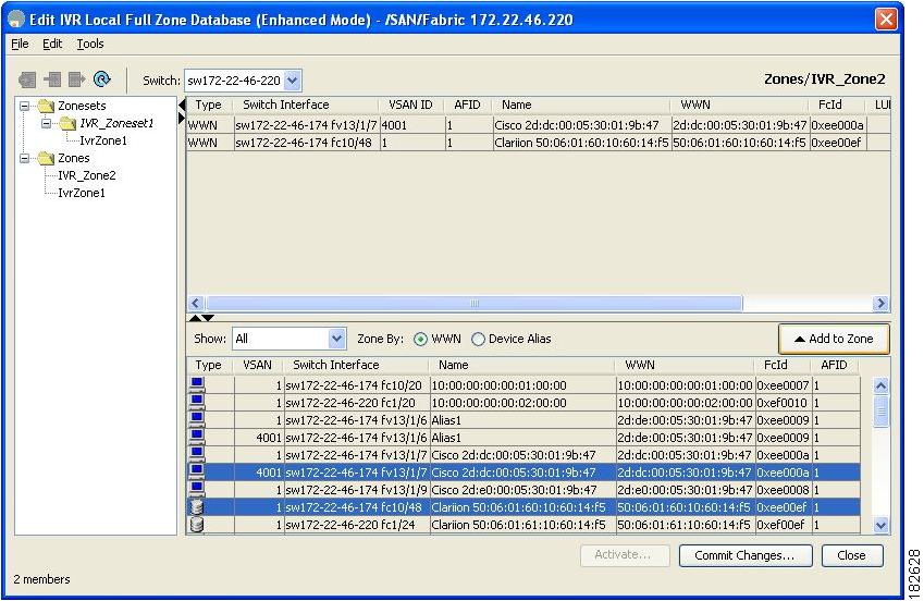
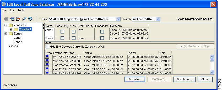
You see the Edit IVR Local Full Zone Database dialog box for the selected VSAN (see Figure 29-15).
Figure 29-15 Edit IVR Local Full Zone Database Dialog Box
If you want to view zone membership information, right-click in the Members column, and then click Show Details for the current row or all rows from the pop-up menu.
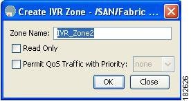
Step 2
You see the Create IVR Zone dialog box shown in Figure 29-16.
Figure 29-16 Create IVR Zone Dialog Box
Step 3
Step 4
a.
b.
Step 5
Step 6
Figure 29-17 Edit IVR Local Full Zone Database Dialog Box
Step 7
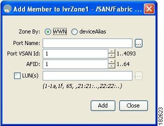
You see the Add Member to Zone dialog box shown in Figure 29-18.
Figure 29-18 Add Member to IVR Zone Dialog Box
Step 8
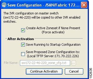
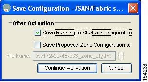
You see the Save Configuration dialog box shown in Figure 29-19.
Figure 29-19 Save Configuration Dialog Box
Step 9
Step 10
Note
In the server.properties file, you can set the property zone.ignoreIVRZones to true or false to either hide or view IVR zones as part of regular active zones. See the "Fabric Manager Server Properties File" section on page 3-5 for more information on the server.properties file.
Note
Step 11
About Activating Zone Sets and Using the force Option
Once the zone sets have been created and populated, you must activate the zone set. When you activate an IVR zone set, IVR automatically adds an IVR zone to the regular active zone set of each edge VSAN. If a VSAN does not have an active zone set, IVR can only activate an IVR zone set using the force option, which causes IVR to create an active zone set called "nozoneset" and adds the IVR zone to that active zone set.
Caution
Note
You can also use the force activate option to activate IVR zone sets. Table 29-4 lists the various scenarios with and without the force activate option.
Table 29-4 IVR Scenarios with and without the Force Activate Option.
1
Deny
No active zone set
No
Failure
No
No
2
Yes
Success
Yes
No
31
Deny
Active zone set present
No/Yes
Success
Yes
No
4
Permit
No active zone set
or
Active zone set presentNo
Failure
No
No
5
Yes
Success
Yes
Yes
1 We recommend that you use the Case 3 scenario.
Cautionpermit, then an IVR zone set activation will fail. However, IVR zone set activation will go through if the force activateoption is used. Because zones are created in the edge VSANs corresponding to each IVR zone, traffic may be disrupted in edge VSANs where the default zone policy ispermit.
To activate or deactivate an existing IVR zone set using Fabric Manager, follow these steps:
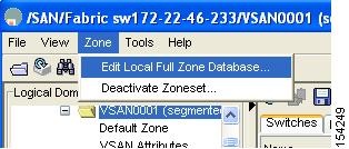
Step 1
Figure 29-20 Zone Menu
You see the Edit Local Full Zone Database dialog box in Figure 29-21.
Figure 29-21 Edit Zone Database Dialog Box
Step 2
You see the Save Configuration dialog box shown in Figure 29-22.
Figure 29-22 Save Configuration Options for a New Zone Set
Step 3
Step 4
Note
Recovering an IVR Full Zone Database
You can recover an IVR zone database by copying the IVR full zone database from another switch.
To recover an IVR zone database using Fabric Manager, follow these steps:
Step 1
You see the Edit IVR Local Full Zone Database dialog box.
Step 2
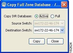
You see the Copy Full Zone Database dialog box shown in Figure 29-23.
Figure 29-23 Copy Full Zone Database Dialog Box
Step 3
Step 4
Step 5
Step 6
Recovering an IVR Full Topology
You can recover a topology by copying from the active zone database or the full zone database.
To recover a zone topology using Fabric Manager, follow these steps:
Step 1
You see the Edit IVR Local Full Zone Database dialog box.
Step 2
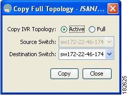
You see the Copy Full Topology dialog box shown in Figure 29-24.
Figure 29-24 Copy Full Topology Dialog Box
Step 3
Step 4
Step 5
Step 6
About LUNs in IVR Zoning
LUN zoning can be used between members of active IVR zones.You can configure the service by creating and activating LUN zones between the desired IVR zone members in all relevant edge VSANs using the zoning interface or you can use LUN zoning directly supported by IVR. For more details on the advantages of LUN zoning, see the "About LUN Zoning" section on page 30-45.
Configuring LUNs in IVR Zoning
You can configure LUN zoning in an IVR zone set setup.
To configure LUNs in IVR zoning, refer to the Cisco MDS 9000 Family CLI Configuration Guide.
About QoS in IVR Zones
You can configure a QoS attribute for an IVR zone. The default QoS attribute setting is low.
Configuring QoS for IVR Zones
To configure QoS for an IVR zone using Fabric Manager, follow these steps:
Step 1
You see the Edit IVR Local Full Zone Database dialog box for the VSAN you selected.
Step 2
Step 3
Step 4
Note
Renaming IVR Zones and IVR Zone Sets
You can rename IVR zones and IVR zone sets.
To rename an IVR zone or IVR zone set, using Fabric Manager, follow the steps below:
Step 1
You see the Edit IVR Local Full Zone Database dialog box for the VSAN you selected.
Step 2
Step 3
An edit box appears around the zone or zone set name.
Step 4
Step 5
Clearing the IVR Zone Database
Clearing a zone set only erases the configured zone database, not the active zone database.
To clear the IVR zone database, refer to the Cisco MDS 9000 CLI Configuration Guide.
Configuring IVR Using Read-Only Zoning
Read-only zoning (with or without LUNs) can be used between members of active IVR zones. To configure this service, you must create and activate read-only zones between the desired IVR zone members in all relevant edge VSANs using the zoning interface.
Note
System Image Downgrading Considerations
As of Cisco MDS SAN-OS Release 3.0(3), you can configure 8000 IVR zones and 20,000 IVR zone members. If you want to downgrade to a release prior to Cisco SAN-OS Release 3.0(3), the number of IVR zones cannot exceed 2000 and the number of IVR zone members cannot exceed 10,000.
Database Merge Guidelines
A database merge refers to a union of the configuration database and static (unlearned) entries in the active database. See the "CFS Merge Support" section on page 13-9 for detailed concepts.
•
–
–
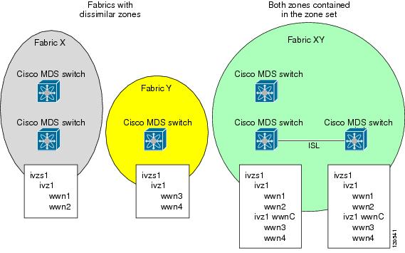
Figure 29-25 Fabric Merge Consequences
•
•
–
–
–
–
–
Note
–
–
Note
–
Note
–
Table 29-5 describes the results of a CFS merge of two IVR-enabled fabrics under different conditions.
Caution
Resolving Database Merge Failures
If a merge failure occurs, use the following commands to display the error conditions:
•
•
•
Depending on the failure indicated in the show command outputs, you can perform the following:
•
•
•
After a successful CFS commit, the merge will be successful.
Default Settings
Table 29-6 lists the default settings for IVR parameters.
Table 29-6 Default IVR Parameters
IVR feature
Disabled.
IVR VSANs
Not added to virtual domains.
IVR NAT
Disabled.
QoS for IVR zones
Low.
Configuration distribution
Disabled.