-
Cisco MDS 9000 Family Fabric Manager Configuration Guide, Release 3.x
-
Index
-
New and Changed Information
-
Preface
- Getting Started
- Installation and Switch Management
- Switch Configuration
-
Fabric Configuration
-
Configuring and Managing VSANs
-
SAN Device Virtualization
-
Creating Dynamic VSANs
-
Configuring Inter-VSAN Routing
-
Distributing Device Alias Services
-
Configuring and Managing Zones
-
Configuring Fibre Channel Routing Services and Protocols
-
Dense Wavelength Division Multiplexing
-
Managing FLOGI, Name Server, FDMI, and RSCN Databases
-
Discovering SCSI Targets
-
Configuring FICON
-
Advanced Features and Concepts
-
-
Security
-
Configuring FIPS
-
Configuring Users and Common Roles
-
Configuring SNMP
-
Configuring RADIUS and TACACS+
-
Configuring IPv4 Access Control Lists
-
Configuring Certificate Authorities and Digital Certificates
-
Configuring IPsec Network Security
-
Configuring FC-SP and DHCHAP
-
Configuring Port Security
-
Configuring Fabric Binding
-
- IP Services
- Intelligent Storage Services
- Network and Switch Monitoring
- Traffic Management
- Troubleshooting
-
Launching Fabric Manager in Cisco SAN-OS Releases Prior to 3.2(1)
-
Cisco Fabric Manager Unsupported Feature List
-
Interface Nonoperational Reason Codes
-
Managing Cisco FabricWare
-
Configuration Limits for Cisco MDS SAN-OS Release 3.1(x) and 3.2(x)
-
 Feedback
Table Of Contents
Configuring Fabric Configuration Servers
Configuring Fabric Configuration Servers
This chapter describes the Fabric Configuration Server (FCS) feature provided in the Cisco MDS 9000 Family of directors and switches. It includes the following sections:
About FCS
The Fabric Configuration Server (FCS) provides discovery of topology attributes and maintains a repository of configuration information of fabric elements. A management application is usually connected to the FCS on the switch through an N port. The FCS views the entire fabric based on the following objects:
•
Interconnect element (IE) object—Each switch in the fabric corresponds to an IE object. One or more IE objects form a fabric.
•
•
Each object has its own set of attributes and values. A null value may also be defined for some attributes.
In the Cisco MDS 9000 Family switch environment, multiple VSANs constitute a fabric, where one instance of the FCS is present per VSAN.
As of Cisco SAN-OS Release 3.1(2), FCS supports the discovery of virtual devices. The fcs virtual-device-add command, issued in FCS configuration submode, allows you to discover virtual devices in a particular VSAN or in all VSANs. The devices that are zoned for IVR must be discovered with this command and have request domain_ID (RDI) enabled, before activating the IVR zone set.
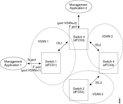
If you have attached a management application to a switch, all the frames directed towards the FCS in the switch are part of the port VSAN in the switch port (Fx port). Hence your view of the management application is limited only to this VSAN. However, information about other VSANs that this switch is part of can be obtained either through the SNMP or CLI.
In Figure 55-1 Management Application 1 (M1) is connected through an F port with port VSAN ID 1, and Management Application 2 (M2) is connected through an F port with port VSAN ID 2. M1 can query the FCS information of switches S1 and S3, and M2 can query switches S3 and S4. Switch S2 information is not known to both of them. FCS operations can be done only on those switches that are visible in the VSAN. Note that M2 can send FCS requests only for VSAN 2 even though S3 is also a part of VSAN 1.
Figure 55-1 FCSs in a VSAN Environment
Significance of FCS
This section lists the significance of FCSs.
•
–
–
•
•
•
Displaying FCS Discovery
To display FCS discovery information using Device Manager, follow these steps:
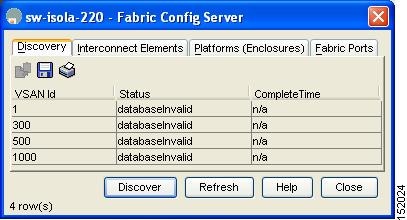
Step 1
You see the Fabric Config Server dialog box shown in Figure 55-2.
Figure 55-2 Fabric Config Server Dialog Box
Step 2
Step 3
Displaying FCS Elements
To display FCS interconnect element information using Device Manager, follow these steps:
Step 1
You see the Fabric Config Server dialog box.
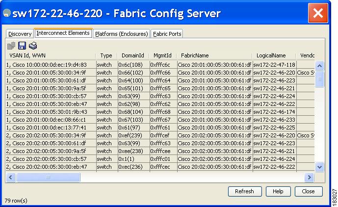
Step 2
You see the dialog box shown in Figure 55-3.
Figure 55-3 FCS Interconnect Elements Tab
Step 3
Creating an FCS Platform
To create an FCS platform using Device Manager, follow these steps:
Step 1
You see the Fabric Config Server dialog box.
Step 2
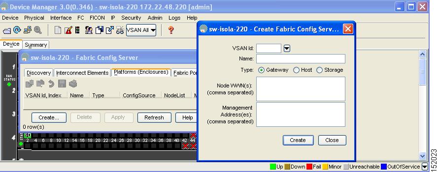
Step 3
You see the Create Fabric Config Server dialog box shown in Figure 55-4.
Figure 55-4 Create Fabric Config Server Dialog Box
Step 4
Step 5
Step 6
Step 7
Step 8
Step 9
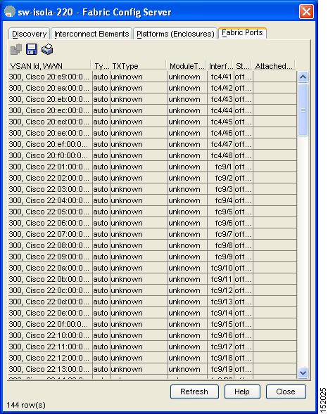
Displaying FCS Fabric Ports
To display FCS discovery information using Device Manager, follow these steps:
Step 1
You see the Fabric Config Server dialog box.
Step 2
You see a list of fabric ports (see Figure 55-5).
Figure 55-5 FCS Fabric Ports
Step 3
Default Settings
Table 55-1 lists the default FCS settings.
Table 55-1 Default FCS Settings
Global checking of the platform name
Disabled.
Platform node type
Unknown.