Cisco MDS 9000 Family Fabric Manager Configuration Guide, Release 3.x
Managing Modules

Table Of Contents

Managing Modules

About Modules

Supervisor Modules

Switching Modules

Services Modules

Verifying the Status of a Module

Obtaining Supervisor Module Statistics

Checking the State of a Module

Reloading Modules

Reloading a Switch

Power Cycling Modules

Preserving Module Configuration

Powering Off Switching Modules

Identifying Module LEDs

Default Settings


Managing Modules


This chapter describes how to manage switching and services modules (also known as line cards) and provides information on monitoring module states.

This chapter includes the following sections:

About Modules, page 19-1

Verifying the Status of a Module, page 19-3

Obtaining Supervisor Module Statistics, page 19-4

Checking the State of a Module, page 19-4

Reloading Modules, page 19-5

Preserving Module Configuration, page 19-7

Powering Off Switching Modules, page 19-8

Identifying Module LEDs, page 19-9

Default Settings, page 19-12

About Modules

Table 19-1 describes the supervisor module options for switches in the Cisco MDS 9000 Family.

Table 19-1 Supervisor Module Options 

Product
Number of Supervisor Modules
Supervisor Module Slot Number
Switching and Services Module Features

Cisco MDS 9513

Two modules

7 and 8

13-slot chassis allows any switching or services module in the other eleven slots.

Cisco MDS 9509

Two modules

5 and 6

9-slot chassis allows any switching or services module in the other seven slots.

Cisco MDS 9506

Two modules

5 and 6

6-slot chassis allows any switching or services module in the other four slots.

Cisco MDS 9216

One module

1

2-slot chassis allows one optional switching or services module in the other slot.

Cisco MDS 9216A

One module

1

2-slot chassis allows one optional switching or services module in the other slot.

Cisco MDS 9216i

One module

1

2-slot chassis allows one optional switching or services module in the other slot.


Supervisor Modules

Supervisor modules are automatically powered up and started with the switch.

Cisco MDS 9513 Directors have two supervisor modules—one in slot 7 (sup-1) and one in slot 8 (sup-2). See Table 19-2. When the switch powers up and both supervisor modules come up together, the active module is the one that comes up first. The standby module constantly monitors the active module. If the active module fails, the standby module takes over without any impact to user traffic.

Cisco MDS 9506 and Cisco MDS 9509 switches have two supervisor modules—one in slot 5 (sup-1) and one in slot 6 (sup-2). See Table 19-2. When the switch powers up and both supervisor modules come up together, the active module is the one that comes up first. The standby module constantly monitors the active module. If the active module fails, the standby module takes over without any impact to user traffic.

Cisco MDS 9216i switches have one supervisor module that includes an integrated switching module with 14 Fibre Channel ports and two Gigabit Ethernet ports.

Cisco MDS 9200 Series switches have one supervisor module that includes an integrated 16-port switching module.

Table 19-2 Supervisor Module Terms and Usage

Module Terms
Fixed or Relative
Usage

module-7 and module-8

Fixed usage for MDS 9513

module-7 always refers to the supervisor module in slot 7 and
module-8 always refers to the supervisor module in slot 8.

module-5 and module-6

Fixed usage for MDS 9509 and MDS 9506

module-5 always refers to the supervisor module in slot 5 and
module-6 always refers to the supervisor module in slot 6.

module-1

Fixed usage for MDS 9200 series

module-1 always refers to the supervisor module in slot 1.

sup-1 and sup-2

Fixed usage

On the MDS 9506 and MDS 9509 switches, sup-1 always refers to the supervisor module in slot 5 and sup-2 always refers to the supervisor module in slot 6.

On the MDS 9513 Directors, sup-1 always refers to the supervisor module in slot 7 and sup-2 always refers to the supervisor module in slot 8.

sup-active and sup-standby

Relative usage

sup-active refers to the active supervisor module—relative to the slot that contains the active supervisor module.

sup-standby refers to the standby supervisor module—relative to the slot that contains the standby supervisor module.

sup-local and sup-remote

Relative usage

If you are logged into the active supervisor, sup-local refers to the active supervisor module and sup-remote refers to the standby supervisor module.

If you are logged into the standby supervisor, sup-local refers to the standby supervisor module (the one you are logged into.) There is no sup-remote available from the standby supervisor module (you cannot access a file system on the active sup).


Switching Modules

Cisco MDS 9000 Family switches support any switching module in any non-supervisor slot. These modules obtain their image from the supervisor module.

Services Modules

Cisco MDS 9000 Family switches support any services module in any non-supervisor slot.

Refer to the Cisco MDS 9000 Family SAN Volume Controller Configuration Guide for more information on CSMs.

Verifying the Status of a Module

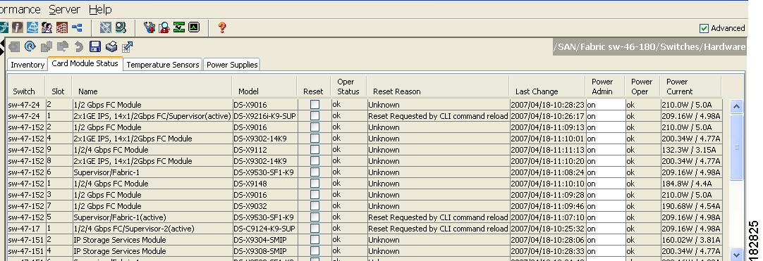
Before you begin configuring the switch, you need to ensure that the modules in the chassis are functioning as designed. To verify the status of a module at any timeexpand Switches and then select Hardware in the Physical Attributes pane in Fabric Manager and select Card Module Status tab in the Information pane (see the "Fibre Channel Interfaces" section on page 20-2). The interfaces in each module are ready to be configured when the ok status is displayed . A sample screenshot follows:

Figure 19-1 Card Module Status Display

The Status column in the output should display an ok status for switching modules and an active or standby (or HA-standby) status for supervisor modules. If the status is either ok or active, you can continue with your configuration..


Note A standby supervisor module reflects the HA-standby status if the HA switchover mechanism is enabled (see the "HA Switchover Characteristics" section on page 17-2). If the warm switchover mechanism is enabled, the standby supervisor module reflects the standby status.


The states through which a switching module progresses is discussed in the "Checking the State of a Module" section on page 19-4.

Obtaining Supervisor Module Statistics

You can view statistics for the supervisor module, such as CPU utilization and NVRAM size, using Fabric Manager. To view supervisor module statistics using Fabric Manager, follow these steps:


Step 1 Do one of the following in the Logical Domains pane:

Expand SAN to display a list of all switches in the SAN.

Click one of the fabrics to display a list of switches for that fabric.

Click a VSAN to display a list of switches for that VSAN.

Step 2 Expand Switches and select Supervisor Statistics in the Physical Attributes pane.

You see the supervisor statistics for each switch in the Information pane.


Checking the State of a Module

The switching module goes through a testing and an initializing stage before displaying an ok status. Table 19-3 describes the possible states in which a module can exist.

Table 19-3 Module States 

Module Status Output
Description

powered up

The hardware has electrical power. When the hardware is powered up, the software begins booting.

testing

The switching module has established connection with the supervisor module and the switching module is performing bootup diagnostics.

initializing

The diagnostics have completed successfully and the configuration is being downloaded.

failure

The switch detects a switching module failure upon initialization and automatically attempts to power-cycle the module three times. After the third attempt it continues to display a failed state.

ok

The switch is ready to be configured.

power-denied

The switch detects insufficient power for a switching module to power up.

active

This module is the active supervisor module and the switch is ready to be configured.

HA-standby

The HA switchover mechanism is enabled on the standby supervisor module (see the "HA Switchover Characteristics" section on page 17-2).

standby

The warm switchover mechanism is enabled on the standby supervisor module (see the "HA Switchover Characteristics" section on page 17-2).


To view the state of a module from Device Manager, choose Physical > Modules. The dialog box displays the status of every module.

Reloading Modules

You can reload the entire switch, reset specific modules in the switch, or reload the image on specific modules in the switch.

This section includes the following totopics:

Reloading a Switch, page 19-5

Power Cycling Modules, page 19-6

Reloading a Switch

To reload a switch using Fabric Manager, follow these steps:


Step 1 Do one of the following in the Logical Domains pane:

Click SAN to display a list of all switches in the SAN.

Click one of the fabrics to display a list of switches for that fabric.

Click a VSAN to display a list of switches for that VSAN.

Step 2 Expand Switches and select Hardware in the Physical Attributes pane.

You see a list of modules contained in the selected switches.

Step 3 Click the Card Module Status tab.

You see the information shown in Figure 19-2.

Figure 19-2 Card Module Status Tab

Step 4 Check the Reset check box in the row of the switch to reload.

Step 5 Click the Apply Changes icon.


Power Cycling Modules

To power cycle any module using Fabric Manager, follow these steps:


Step 1 Do one of the following in the Logical Domains pane:

Click SAN to display a list of all switches in the SAN.

Click one of the fabrics to display a list of switches for that fabric.

Click a VSAN to display a list of switches for that VSAN.

Step 2 Expand Switches and select Hardware from the Physical Attributes pane.

Step 3 Click the Card Module Status tab.

Step 4 Check the Reset check box in the row for the module(s) you want to reset.

Step 5 Click the Apply Changes icon.


Caution Resetting a module disrupts traffic through the module.

Preserving Module Configuration

Use the "copy running-config to startup-config" procedure to save the new configuration into nonvolatile storage. Once this procedure is complete, the running and the startup copies of the configuration are identical.

To preserve the module configuration using Fabric Manager, follow these steps:


Step 1 Do one of the following in the Logical Domains pane:

Click SAN to display a list of all switches in the SAN.

Click one of the fabrics to display a list of switches for that fabric.

Click a VSAN to display a list of switches for that VSAN.

Step 2 Expand Switches and select Copy Configuration in the Physical Attributes pane.

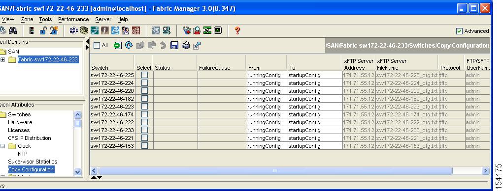
You see a list of switches (see Figure 19-3).

Figure 19-3 List of Switches Available to Copy

Step 3 Click individual Select check boxes for switch configurations to copy.

Step 4 In the From column, ensure that runningConfig is selected.

Step 5 In the To column, ensure that startupConfig is selected.

Step 6 Click the Apply Changes icon.


Table 19-4 displays various scenarios when module configurations are preserved or lost.

Table 19-4 Switching Module Configuration Status 

Scenario
Consequence

A particular switching module is removed and the copy running-config startup-config command is issued again.

The configured module information is lost.

A particular switching module is removed and the same switching module is replaced before the copy running-config startup-config command is issued again.

The configured module information is preserved.

A particular switching module is removed and replaced with the same type switching module, and a reload module number command is issued.

The configured module information is preserved.

A particular switching module is reloaded when a reload module number command is issued.

The configured module information is preserved.

A particular switching module is removed and replaced with a different type of switching module. For example, a 16-port switching module is replaced with a 32-port switching module.

Sample scenario:

1. The switch currently has a 16-port switching module and the startup and running configuration files are the same.

2. You replace the 16-port switching module in the switch with a 32-port switching module.

3. Next, you remove the 32-port switching module and replace it with the same 16-port switching module referred to in Step 1.

4. You reload the switch.

The configured module information is lost from the running configuration. The default configuration is applied.

The configured module information remains in startup configuration until a copy running-config startup-config command is issued again.

Sample response:

1. The switch uses the 16-port switching module and the present configuration is saved in nonvolatile storage.

2. The factory default configuration is applied.

3. The factory default configuration is applied.

4. The configuration saved in nonvolatile storage referred to in Step 1 is applied.


Powering Off Switching Modules

By default, all switching modules are in the power up state.

To power off a module using Fabric Manager, follow these steps:


Step 1 Do one of the following in the Logical Domains pane:

Click SAN to display a list of all switches in the SAN.

Click one of the fabrics to display a list of switches for that fabric.

Step 2 Expand Switches and select Hardware in the Physical Attributes pane.

You see a list of modules contained in the selected switches.

Step 3 Select off from the drop-down list in the row for the module(s) you want to power off.

Step 4 Click the Apply Changes icon.


Note To power on a module, repeat Steps 1-4 but select on in Step 3.


Identifying Module LEDs

Table 19-5 describes the LEDs for the Cisco MDS 9200 Series integrated supervisor modules.

Table 19-5 LEDs for the Cisco MDS 9200 Series Supervisor Modules  

LED
Status
Description

Status

Green

All diagnostics pass. The module is operational (normal initialization sequence).

Orange

One of the following applies:

The module is booting or running diagnostics (normal initialization sequence).

The inlet air temperature of the system has exceeded the maximum system operating temperature limit (a minor environmental warning). To ensure maximum product life, you should immediately correct the environmental temperature and restore the system to normal operation.

Red

One of the following applies:

The diagnostic test failed. The module is not operational because a fault occurred during the initialization sequence.

The inlet air temperature of the system has exceeded the safe operating temperature limits of the card (a major environmental warning). The card has been shut down to prevent permanent damage. The system will be shut down after two minutes if this condition is not cleared.

Speed

On

2-Gbps mode and beacon mode disabled.

Off

1-Gbps mode and beacon mode disabled.

Flashing

Beacon mode enabledSee the "Identifying the Beacon LEDs" section on page 20-14.

Link

Solid green

Link is up.

Solid yellow

Link is disabled by software.

Flashing yellow

A fault condition exists.

Off

No link.


Table 19-6 describes the LEDs for the Cisco MDS 9200 Series interface module.

Table 19-6 LEDs on the Cisco MDS 9200 Series Interface Module 

LED
Status
Description

Status

Green

All diagnostics pass. The module is operational (normal initialization sequence).

Orange

One of the following applies:

The module is booting or running diagnostics (normal initialization sequence).

The inlet air temperature of the system has exceeded the maximum system operating temperature limit (a minor environmental warning). To ensure maximum product life, you should immediately correct the environmental temperature and restore the system to normal operation.

Red

One of the following applies:

The diagnostic test failed. The module is not operational because a fault occurred during the initialization sequence.

The inlet air temperature of the system has exceeded the safe operating temperature limits of the card (a major environmental warning). The card has been shut down to prevent permanent damage.

System

Green

All chassis environmental monitors are reporting OK.

Orange

One of the following applies:

The power supply failed or the power supply fan failed.

Incompatible power supplies are installed.

The redundant clock failed.

Red

The temperature of the supervisor module exceeded the major threshold.

MGMT 10/100 Ethernet Link LED

Green

Link is up.

Off

No link.

MGMT 10/100 Ethernet Activity LED

Green

Traffic is flowing through port.

Off

No link or no traffic.


Table 19-7 describes the LEDs for the 16-port and 32-port switching modules, and the 4-port, 12-port, 24-port, and 48-port Generation 2 switching modules.

Table 19-7 LEDs for the Cisco MDS 9000 Family Fibre Channel Switching Modules 

LED
Status
Description

Status

Green

All diagnostics pass. The module is operational (normal initialization sequence).

Orange

One of the following applies:

The module is booting or running diagnostics (normal initialization sequence).

The inlet air temperature of the system has exceeded the maximum system operating temperature limit (a minor environmental warning). To ensure maximum product life, you should immediately correct the environmental temperature and restore the system to normal operation.

Red

One of the following applies:

The diagnostic test failed. The module is not operational because a fault occurred during the initialization sequence.

The inlet air temperature of the system has exceeded the safe operating temperature limits of the card (a major environmental warning). The card has been shut down to prevent permanent damage.

Speed

On

2-Gbps mode.

Off

1-Gbps mode.

Link

Solid green

Link is up.

Steady flashing green

Link is up (beacon used to identify port).

Intermittent flashing green

Link is up (traffic on port).

Solid yellow

Link is disabled by software.

Flashing yellow

A fault condition exists.

Off

No link.


The LEDs on the supervisor module indicate the status of the supervisor module, power supplies, and the fan module. Table 19-8 provides more information about these LEDs.

Table 19-8 LEDs for the Cisco MDS 9500 Series Supervisor Modules 

LED
Status
Description

Status

Green

All diagnostics pass. The module is operational (normal initialization sequence).

Orange

One of the following applies:

The module is booting or running diagnostics (normal initialization sequence).

An over temperature condition has occurred (a minor threshold has been exceeded during environmental monitoring).

Red

One of the following applies:

The diagnostic test failed. The module is not operational because a fault occurred during the initialization sequence.

An over temperature condition occurred (a major threshold was exceeded during environmental monitoring).

System1

Green

All chassis environmental monitors are reporting OK.

Orange

One of the following applies:

The power supply has failed or the power supply fan has failed.

Incompatible power supplies are installed.

The redundant clock has failed.

Red

The temperature of the supervisor module major threshold has been exceeded.

Active

Green

The supervisor module is operational and active.

Orange

The supervisor module is in standby mode.

Pwr Mgmt1

Green

Sufficient power is available for all modules.

Orange

Sufficient power is not available for all modules.

MGMT 10/100 Ethernet Link LED

Green

Link is up.

Off

No link.

MGMT 10/100 Ethernet Activity LED

Green

Traffic is flowing through port.

Off

No link or no traffic.

CompactFlash

Green

The external CompactFlash card is being accessed.

Off

No activity.

1 The System and Pwr Mgmt LEDs on a redundant supervisor module are synchronized to the active supervisor module.


Default Settings

Table 19-9 lists the default settings for the supervisor module.

Table 19-9 Default Supervisor Module Settings 

Parameters
Default

Administrative connection

Serial connection.

Global switch information

No value for system name.

No value for system contact.

No value for location.

System clock

No value for system clock time.

In-band (VSAN 1) interface

IP address, subnet mask, and broadcast address assigned to the VSAN are set to 0.0.0.0.


Table 19-10 lists the default settings for the SSM.

Table 19-10 Default SSM Settings 

Parameters
Default

Initial state when installed

Power-down state on switches with Cisco MDS SAN-OS Release 2.1(1a) and earlier installed.

Fibre Channel switching mode on switches with Cisco MDS SAN-OS Release 2.1(2) and later installed and SSMs with EPLD version 2.0(2) and later installed.