Configure Integrated Routing and Bridging

This module describes the configuration of Integrated Routing and Bridging (IRB) on the Cisco 8000 Series Routers. IRB provides the ability to exchange traffic between bridging services on the Cisco 8000 Series Router and a routed interface using a Bridge-Group Virtual Interface (BVI).

Table 1. Feature History Table

Feature Name

Release Information

Feature Description

Integrated Routing and Bridging with Bridge-Group Virtual Interface

Release 25.2.1

Introduced in this release on: Fixed Systems (8200 [ASIC: P100]); Fixed Systems (8700 [ASIC: P100]); Modular Systems (8800 [LC ASIC: P100])

Integrated Routing and Bridging (IRB) provides the ability to exchange traffic between bridging services on a router and a routed interface using a Bridge-Group Virtual Interface (BVI). IRB over BVI enables seamless communication between Layer 2 bridging and Layer 3 routing by using BVI as a logical interface.

*This feature is supported on:
  • 8212-48FH-M

  • 88-LC1-36EH

  • 8711-32FH-M

Integrated Routing and Bridging (IRB)

Release 25.1.1

Introduced in this release on: Modular Systems (8800 [LC ASIC: P100]) (select variants only*)

Integrated Routing and Bridging (IRB) provides the ability to exchange traffic between bridging services on a router and a routed interface using a Bridge-Group Virtual Interface (BVI). IRB over BVI enables seamless communication between Layer 2 bridging and Layer 3 routing by using BVI as a logical interface.

*This feature is supported on:
  • 88-LC1-12TH24FH-E

  • 88-LC1-52Y8H-EM

Prerequisites to configure IRB

You must be in a user group associated with a task group that includes the proper task IDs. The command reference guides include the task IDs required for each command. If you suspect user group assignment is preventing you from using a command, contact your AAA administrator for assistance.

Before configuring IRB, be sure that these tasks and conditions are met:

  • Confirm that you are configuring the required line cards where you plan to support IRB in support of both Layer 3 to Layer 2 traffic flows and Layer 2 to Layer 3 traffic flows

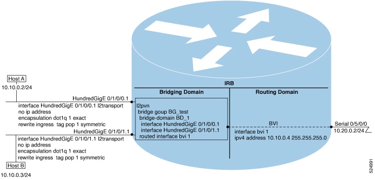
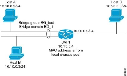
  • Know the IP addressing and other Layer 3 information to be configured on the bridge virtual interface (BVI). For more information, see the “Restrictions for Configuring IRB” section on page 265.

  • Complete MAC address planning if you decide to override the common global MAC address for all BVIs.

  • Be sure that the BVI network address is being advertised by running static or dynamic routing on the BVI interface.

Guidelines and restrictions to configure IRB

Before configuring IRB, consider these restrictions:

  • Only one BVI can be configured in any bridge domain.

  • The same BVI can not be configured in multiple bridge domains.

  • The following areas are not supported on the BVI:

    • IP fast reroute (FRR)

    • MoFRR

    • Traffic mirroring

    • Unnumbered interface for BVI

  • Multi protocol Label Switching (MPLS) on BVI is supported.

  • PIM snooping. (Need to use selective flood.)

  • VRF-aware DHCP relay is supported.

  • BVIs are supported only on bridge domains with the following characteristics:

    • The bridge domain supports single and double-tagged dot1q- and dot1ad-encapsulated EFPs with non-ambiguous or “exact match” EFP encapsulations. Single and double-tagged encapsulation can be specified as long as the rewrite ingress tag pop symmetric command is configured.

    • All Layer 2 tags must be removed. VLAN ranges are not supported.

    • Untagged EFPs are supported.

  • To use the sub-interface configurations encapsulation dot1ad (or encapsulation dot1q ) and encapsulation dot1ad second-dot1q any (or encapsulation dot1q second-dot1q any ) together on the same physical interface, use the exact keyword as shown below. Else, it results in traffic loss.

    Router(config)# interface hundredGigE 0/0/0/0.0 
    Router(config-subif)# encapsulation dot1ad 200 exact 
    
    Router(config)# interface hundredGigE 0/0/0/0.1 
    Router(config-subif)# encapsulation dot1ad 200 dot1q any 
    Router(config-subif)# commit 
    
  • QoS on BVI is not supported on Cisco 8000 routers. Any QoS policy configuration on BVI will be rejected.

Information about configuring IRB

This section includes the following topics:

IRB introduction

IRB provides the ability to route between a bridge group and a routed interface using a BVI. The BVI is a virtual interface within the router that acts like a normal routed interface. A BVI is associated with a single bridge domain and represents the link between the bridging and the routing domains on the router. To support receipt of packets from a bridged interface that are destined to a routed interface, the BVI must be configured with the appropriate IP addresses and relevant Layer 3 attributes.

In software releases before Cisco IOS XR 4.0.1 where IRB is not supported, you would need to implement a physical cabling solution to connect the egress Layer 2 bridge domain interface to a Layer 3 routing domain interface on the same Cisco 8000 Series Router. In Cisco IOS XR Release 4.0.1, IRB accomplishes the same functionality using a BVI and its supporting interface and bridge group configuration shown in this figure.

Figure 1. IRB Functional View and Configuration Elements

Bridge-Group Virtual Interface

This section includes the following information:

Bridge-Group Virtual Interface

The BVI is a virtual interface within the router that acts like a normal routed interface. The BVI does not support bridging itself, but acts as a gateway for the corresponding bridge-domain to a routed interface within the router.

Aside from supporting a configurable MAC address, a BVI supports only Layer 3 attributes, and has the following characteristics:

  • Uses a MAC address taken from the local chassis MAC address pool, unless overridden at the BVI interface.

  • Is configured as an interface type using the interface BVI command and uses an IPv4 address that is in the same subnet as the hosts on the segments of the bridged domain. The BVI also supports secondary addresses.

  • The BVI identifier is independent of the bridge-domain identifier. These identifiers do not need to correlate like they do in Cisco IOS software.

  • Is associated to a bridge group using the routed interface BVI command.

  • BVI interfaces support a number range of 1 to 4294967295.

Supported features on BVI

The following are the supported features on BVI:

  • Border Gateway Protocol (BGP)

  • Bidirectional Forwarding Detection (BFD)

  • Open Shortest Path First (OSPF)

  • Integrated Intermediate System-to-Intermediate System (IS-IS)

  • Netflow

  • Access Control Lists

These interface commands are supported on a BVI:

  • arp purge-delay

  • arp timeout

  • bandwidth (The default is 10 Gbps and is used as the cost metric for routing protocols for the BVI)

  • ipv4

  • ipv6

  • mac-address

  • mtu (The default is 1500 bytes)

  • shutdown

  • The BVI supports IP helper addressing and secondary IP addressing.

BVI MAC address

By default, the Cisco 8000 Series Router uses one MAC address for all BVI interfaces on the router. However, this means that the MAC address is not unique globally. If you want to override the default and specify a unique MAC address at the BVI, then you can configure it at the BVI interface.

BVI interface and line protocol states

Like typical interface states on the router, a BVI has both an Interface and Line Protocol state.

  • The BVI interface state is Up when the following occurs:

    • The BVI interface is created.

    • The bridge-domain that is configured with the routed interface bvi command has at least one available active bridge port (Attachment circuit [AC] or pseudowire [PW]).


      Note


      A BVI will be moved to the Down state if all of the bridge ports (Ethernet flow points [EFPs]) associated with the bridge domain for that BVI are down. However, the BVI will remain up if at least one pseudowire is up, even if all EFPs are down.


  • The following characteristics determine when the the BVI line protocol state is up:

    • The bridge-domain is in Up state.

    • The BVI IP address is not in conflict with any other IP address on another active interface in the router.

Packet flows using IRB

This figure shows a simplified functional diagram of an IRB implementation to describe different packet flows between Host A, B, and C. In this example, Host C is on a network with a connection to the same router. In reality, another router could be between Host C and the router shown.

Figure 2. IRB packet flows between hosts

When IRB is configured on a router, the following processing happens:

  • ARP requests are resolved between the hosts and BVI that are part of the bridge domain.

  • All packets from a host on a bridged interface go to the BVI if the destination MAC address matches the BVI MAC address. Otherwise, the packets are bridged.

  • For packets destined for a host on a routed network, the BVI forwards the packets to the routing engine before sending them out a routed interface.

  • All packets either from or destined to a host on a bridged interface go to the BVI first (unless the packet is destined for a host on the bridge domain).

  • For packets that are destined for a host on a segment in the bridge domain that come in to the router on a routed interface, the BVI forwards the packet to the bridging engine, which forwards it through the appropriate bridged interface.

Packet flows when host A sends to host B on the bridge domain

When host A sends data to host B in the bridge domain on the 10.10.0.0 network, no routing occurs. The hosts are on the same subnet and the packets are bridged between their segment interfaces on the router.

Packet flows when host A sends to host C from the bridge domain to a routed interface

Using host information from this figure, the following occurs when host A sends data to host C from the IRB bridging domain to the routing domain:

  • Host A sends the packet to the BVI (as long any ARP request the is resolved between the host and the BVI). The packet has the following information:

    • Source MAC address of host A.

    • Destination MAC address of the BVI.

  • Since host C is on another network and needs to be routed, the BVI forwards the packet to the routed interface with the following information:

    • IP source MAC address of host A (10.10.0.2) is changed to the MAC address of the BVI (10.10.0.4).

    • IP destination address is the IP address of host C (10.20.0.3).

  • Interface 10.20.0.2 sees receipt of a packet from the routed BVI 10.10.0.4. The packet is then routed through interface 10.20.0.2 to host C.

Packet flows when host C sends to host B from a routed interface to the bridge domain

Using host information from this figure, the following occurs when host C sends data to host B from the IRB routing domain to the bridging domain:

  • The packet comes into the routing domain with the following information:

    • MAC source address—MAC of host C.

    • MAC destination address—MAC of the 10.20.0.2 ingress interface.

    • IP source address—IP address of host C (10.20.0.3).

    • IP destination address—IP address of host B (10.10.0.3).

  • When interface 10.20.0.2 receives the packet, it looks in the routing table and determines that the packet needs to be forwarded to the BVI at 10.10.0.4.

  • The routing engine captures the packet that is destined for the BVI and forwards it to the BVI’s corresponding bridge domain. The packet is then bridged through the appropriate interface if the destination MAC address for host B appears in the bridging table, or is flooded on all interfaces in the bridge group if the address is not in the bridging table.

Supported environments for IRB

These environments and configuration elements are supported with IRB on the Cisco 8000 Series Router:

  • Configuration of one BVI per bridge domain.

  • Virtual Private LAN Service (VPLS) virtual forwarding instance (VFI) configuration associated with a bridge domain configured with a BVI.

  • BGP PIC edge for BVI-based prefixes.

  • Traffic forwarding for the BVI using Open Shortest Path First (OSPF), Intermediate System-to-Intermediate System (IS-IS), and Border Gateway Protocol (BGP).

  • Internet Group Management Protocol (IGMP) static groups.

  • Dynamic Host Configuration Protocol (DHCP) relay agent. When DHCP relay is used from an aggregation node to obtain an IP address, the default gateway will be the IP address configured on the BVI. The BVI IP address should be in a common subnet as the DHCP pool that is being used by the aggregation node to assign IP addresses.

  • Virtual Router Redundancy Protocol (VRRP) configuration and priority.

  • Hot Standby Router Protocol (HSRP).

  • Up to 255 VRRP or HSRP virtual MAC addresses can be configured on a physical or bundle interface, with each VRRP or HSRP ID assigned to only one BVI interface.

  • Bridging of non-IP packets on a bridge domain configured with a BVI.

  • Parity with stateful protocol support as currently supported on Layer 3 subinterfaces on the Cisco 8000 Series Router.

  • IP SLA support as currently supported on Layer 3 subinterfaces on the Cisco 8000 Series Router.

  • Load balancing of BVIs as ECMP paths (up to 32 paths).

  • Interface-MIB.

  • Packet counters for BVI interfaces.

The following sections document additional IPv4- and IPv6-specific environments supported for IRB.

Additional IPv4-specific environments supported for IRB

  • Layer 3 IP multicast, with ability to take ingress IP multicast traffic and bridge it to multiple Layer 2 subinterfaces (Ethernet flow points) on a bridge domain that are part of multicast groups.

  • VRFs for IPv4 (Per-VPN label VRFs only—not per prefix).

Additional IPv6-specific environments supported for IRB

Cisco IPv6 Provider Edge Router over MPLS (6PE) and IPv6 VPN Provider Edge (6VPE) support with BVI interfaces at the customer edge (CE)-facing side of the Cisco 8000 Series Router as the PE device with the following restriction:

Only per-VRF label allocation is supported (using the label-allocation-mode per-vrf command). For a configuration example, see the “6PE/6VPE With BVI Configuration: Example” section on page 282

How to configure IRB

This section includes the following configuration tasks:

Configure BVI

To configure a BVI, complete the following steps.

Configuration guidelines

Consider the following guidelines when configuring the BVI:

  • The BVI must be assigned to an IPv4 or IPv6 address that is in the same subnet as the hosts in the bridged segments.

  • If the bridged network has multiple IP networks, then the BVI must be assigned secondary IP addresses for each network.

Procedure

Step 1

Run the configure command to enter the global configuration mode.

Example:
Router#configure

Step 2

Run the interface bvi identifier command to specify and create a BVI, where identifier is a number from 1–65535.

Example:
Router(config)#interface bvi 1

Step 3

Specify a primary or secondary IPv4 address or an IPv6 address for the interface.

Example:
Router(config-if)#ipv4 address 10.10.0.4 255.255.255.0

Step 4

(Optional) Specify the amount of time (in seconds) to delay purging of Address Resolution Protocol (ARP) table entries when the interface goes down.

Example:

Router(config-if)#arp purge-delay 120

The range is 1–65535. By default, purge delay is not configured.

Step 5

(Optional) Run the arp timeout seconds command to configure the duration that the dynamic entries learned on the interface remain in the ARP cache.

Example:

Router(config-if)#arp timeout 12200

The range is 30–2144448000 seconds. The default value is 14,400 seconds (4 hours).

Step 6

(Optional) Specify the amount of bandwidth (in kilobits per second) to be allocated on the interface.

Example:

Router(config-if)#bandwidth 1000000

This bandwidth number is used as the cost metric in routing protocols for the BVI. The range is 0–4294967295. The default value is 10000000 (10 Gbps).

Step 7

(Optional) Specify the 48-bit MAC address for the BVI as three dotted-hexadecimal values, which override the use of the default MAC address.

Example:
Router(config-if)#mac-address 1111.2222.3333

The range for each value is 0000 to ffff. A MAC address of all 0s is not supported.

Step 8

(Optional) Run the mtu bytes command to configure the maximum transmission unit (MTU) size for packets on the interface.

Example:

Router(config-if)# mtu 2000

The range is 64–65535. The default value is 1514.

Step 9

Run the end or commit commands to save the configuration changes.

Example:
Router(config-if)#end

or


Router(config-if)#commit
  • When you issue the end command, the system prompts you to commit changes:

    
    Uncommitted changes found, commit them before exiting(yes/no/cancel)?
    [cancel]:
    

    Entering yes saves configuration changes to the running configuration file, exits the configuration session, and returns the router to EXEC mode.

    Entering no exits the configuration session and returns the router to EXEC mode without committing the configuration changes.

    Entering cancel leaves the router in the current configuration session without exiting or committing the configuration changes.

  • Use the commit command to save the configuration changes to the running configuration file and remain within the configuration session.


Configure Layer 2 AC interfaces

To configure the Layer 2 AC interfaces for routing by a BVI, complete the following steps.

Before you begin

The interfaces to be configured as Layer 2 ACs in the bridge domain and routed by a BVI must be located on the Cisco 8000 Series Router.

Procedure


Step 1

Run the configure command to enter the global configuration mode.

Example:


Router#configure

Step 2

Run the interface [HundredGigE] interface-path-id[ .subinterface] l2transport command to enable Layer 2 transport mode on a HundredGigE interface or subinterface and enter the interface or subinterface configuration mode.

Example:

Router(config)#interface HundredGigE 0/1/0/0.1 l2transport

The interface-path-id is specified as the rack/slot/module/port location of the interface and .subinterface is the optional subinterface number.

Step 3

(Optional) Run the encapsulation dot1q vlan-id [exact] orencapsulation dot1ad vlan-id dot1q vlan-id command to configure the IEEE 802.1Q encapsulation on the specified VLAN only.

Example:

Router(config-if)#encapsulation dot1q 1 exact

Step 4

(Required if VLAN tagging configured) Specify the one or two tags (depending on the network configuration) that should be removed from frames arriving at the ingress interface to the bridge domain.

Example:

Router(config-if)#rewrite ingress tag pop 1 symmetric

Note


When you configure double tags using dot1ad and dot1q encapsulation, you must use the rewrite ingress tag pop 2 symmetric command.

Step 5

Run the end or commit commands to save the configuration changes.

Example:

Router(config-if)#end

or

Router(config-if)#commit
  • When you issue the end command, the system prompts you to commit changes:

    
    Uncommitted changes found, commit them before exiting(yes/no/cancel)?
    [cancel]:
    
  • Entering yes saves configuration changes to the running configuration file, exits the configuration session, and returns the router to EXEC mode.

  • Entering no exits the configuration session and returns the router to EXEC mode without committing the configuration changes.

  • Entering cancel leaves the router in the current configuration session without exiting or committing the configuration changes.

  • Use the commit command to save the configuration changes to the running configuration file and remain within the configuration session.


Configure a bridge group and assign interfaces to a bridge domain

To configure a bridge group and assign interfaces to a bridge domain, complete the following steps.

Procedure


Step 1

In the global configuration mode, run the l2vpn command to enter the L2VPN configuration mode.

Example:


Router(config)#l2vpn

Step 2

Run the bridge group bridge-group-name command to create a bridge group and enter the L2VPN bridge group configuration mode.

Example:


Router(config-l2vpn)#bridge group 10

Step 3

Run the bridge-domain bridge-domain-name command to create a bridge domain and enter L2VPN bridge group bridge domain configuration mode.

Example:

Router(config-l2vpn-bg)#bridge-domain BD_1

Step 4

Associate a HundredGigE interface with the specified bridge domain and enter the L2VPN bridge group bridge domain attachment circuit configuration mode.

Example:


Router(config-l2vpn-bg-bd)#interface HundredGigE 0/1/0/0.1

The interface-path-id is specified as the rack/slot/module/port location of the interface and .subinterface is the optional subinterface number.

Repeat this step for as many interfaces as you want to associate with the bridge domain.

Step 5

Run the end or commit commands to save the configuration changes.

Example:


Router(config-l2vpn-bg-bd-ac)#end

or

Router(config-l2vpn-bg-bd-ac)#commit
  • When you issue the end command, the system prompts you to commit changes:

    
    Uncommitted changes found, commit them before exiting(yes/no/cancel)?
    [cancel]:
    
  • Entering yes saves configuration changes to the running configuration file, exits the configuration session, and returns the router to EXEC mode.

  • Entering no exits the configuration session and returns the router to EXEC mode without committing the configuration changes.

  • Entering cancel leaves the router in the current configuration session without exiting or committing the configuration changes.

  • Use the commit command to save the configuration changes to the running configuration file and remain within the configuration session.


Associate BVI as a routed Interface on a bridge domain

To associate the BVI as the routed interface on a bridge domain, complete the following steps.

Procedure


Step 1

In the global configuration mode, run the l2vpn command to enter the L2VPN configuration mode.

Example:


Router(config)#l2vpn

Step 2

Create a bridge group and enter the L2VPN bridge group configuration mode.

Example:

Router(config-l2vpn)#bridge group BG_test

Step 3

Run the bridge-domain bridge-domain-name command to create a bridge domain and enter the L2VPN bridge group bridge domain configuration mode.

Example:

Router(config-l2vpn-bg)#bridge-domain 1

Step 4

Associate the specified BVI as the routed interface for the interfaces that are assigned to the bridge domain.

Example:

Router(config-l2vpn-bg-bd)# routed interface bvi 1

Step 5

Run the end or commit commands to save the configuration.

Example:


Router(config-l2vpn-bg-bd)#end

or

Router(config-l2vpn-bg-bd)#commit
  • When you issue the end command, the system prompts you to commit changes:

    
    Uncommitted changes found, commit them before exiting(yes/no/cancel)?
    [cancel]:
    
  • Entering yes saves configuration changes to the running configuration file, exits the configuration session, and returns the router to EXEC mode.

  • Entering no exits the configuration session and returns the router to EXEC mode without committing the configuration changes.

  • Entering cancel leaves the router in the current configuration session without exiting or committing the configuration changes.

  • Use the commit command to save the configuration changes to the running configuration file and remain within the configuration session.


Display information about BVI

To display information about the BVI status and packet counters, use the following commands:

Command Purpose

show interfaces bvi identifier [accounting | brief | description | detail ]

Displays interface status, line protocol state, and packet counters for the specified BVI.

show adjacency bvi identifier [detail | remote]

Displays packet and byte transmit counters per adjacency to the specified BVI.

show l2vpn bridge-domain detail

Displays the reason that a BVI is down.

Configuration examples for IRB

This section provides the following configuration examples:

Basic IRB configuration: example

The following example shows how to perform the most basic IRB configuration:


! Configure the BVI and its IPv4 address
!
Router#configure
Router(config)#interface bvi 1
Router(config-if))#ipv4 address 10.10.0.4 255.255.255.0
Router(config-if))#exit
!
! Configure the Layer 2 AC interface
!
Router(config)#interface HundregGigE 0/1/0/0 l2transport
Router(config-if))#exit
!
! Configure the L2VPN bridge group and bridge domain and assign interfaces
!
Router(config)#l2vpn
Router(config-l2vpn)#bridge group 10
Router(config-l2vpn-bg)#bridge-domain 1
Router(config-l2vpn-bg-bd)#interface HundregGigE 0/1/0/0
Router(config-l2vpn-bg-bd-if)#exit
!
! Associate a BVI to the bridge domain
!
Router(config-l2vpn-bg-bd)#routed interface bvi 1
Router(config-l2vpn-bg-bd)#commit

IRB using ACs with VLANs: example

The following example shows how to configure IRB on a bridge domain with Layer 2 ACs using 802.1Q-encapsulated VLANs:


! Configure the BVI and its IPv4 address
!
Router#configure
Router(config)#interface bvi 1
Router(config-if))#ipv4 address 10.10.0.4 255.255.255.0
Router(config-if))#exit
!
! Configure the Layer 2 AC interfaces using dot1q encapsulation on a VLAN
!
Router(config)#interface HundredGigE 0/1/0/0.1 l2transport
Router(config-if))#no ip address
Router(config-if))#encapsulation dot1q 1 exact
Router(config-if))#rewrite ingress tag pop 1 symmetric
Router(config-if))#exit
Router(config)#interface HundredGigE 0/1/0/1.1 l2transport
Router(config-if))#no ip address
Router(config-if))#encapsulation dot1q 1 exact
Router(config-if))#rewrite ingress tag pop 1 symmetric
Router(config-if))#exit
!
! Configure the L2VPN bridge group and bridge domain and assign interfaces
!

Router(config)#l2vpn
Router(config-l2vpn)#bridge group 10
Router(config-l2vpn-bg)#bridge-domain 1
Router(config-l2vpn-bg-bd)#interface HundredGigE 0/1/0/0.1
Router(config-l2vpn-bg-bd)#interface HundredGigE 0/1/0/1.1
Router(config-l2vpn-bg-bd-if)#exit
!
! Associate a BVI to the bridge domain
!
Router(config-l2vpn-bg-bd)#routed interface bvi 1
Router(config-l2vpn-bg-bd)#commit

IPv4 addressing on a BVI supporting multiple IP networks: example

The following example shows how to configure secondary IPv4 addresses on a BVI that supports bridge domains for the 10.10.10.0/24, 10.20.20.0/24, and 10.30.30.0/24 networks. In this example, the BVI must have an address on each of the bridge domain networks:


Router#configure
Router(config)#interface bvi 1
Router(config-if))#ipv4 address 10.10.10.4 255.255.255.0
Router(config-if))#ipv4 address 10.20.20.4 255.255.255.0 secondary
Router(config-if))#ipv4 address 10.30.30.4 255.255.255.0 secondary
Router(config-if))#commit

Comprehensive IRB configuration with BVI bundle interfaces and multicast configuration: example

The following example shows a more comprehensive router configuration with IRB and BVI multicast support:


interface Bundle-Ether25
 ipv4 address 10.21.0.2 255.255.255.0
!
interface Loopback0
 ipv4 address 10.5.5.5 255.255.255.255
!
interface HundredGigE0/0/0/1
 negotiation auto
!
interface HundredGigE0/0/0/1.1 l2transport
 encapsulation dot1q 1
 rewrite ingress tag pop 1 symmetric
!
interface HundredGigE0/0/0/1.2 l2transport
 encapsulation dot1q 2
 rewrite ingress tag pop 1 symmetric
!

interface HundredGigE0/0/0/9
 bundle id 25 mode active
!
interface HundredGigE0/0/0/19
 bundle id 25 mode active
!
interface HundredGigE0/0/0/29
 bundle id 25 mode active
!

interface HundredGigE0/0/0/39
 bundle id 25 mode active

interface BVI1
 ipv4 address 10.1.1.1 255.255.255.0
!
interface BVI2
 ipv4 address 10.1.2.1 255.255.255.0

router ospf 100
 router-id 10.5.5.5
 area 0
  interface Bundle-Ether25
    interface Loopback0
    interface BVI1
   interface BVI2
  !
l2vpn
 bridge group IRB
  bridge-domain IRB1
   igmp snooping profile IRB_SNOOP
   interface HundredGigE0/0/0/1.1
   !
   routed interface BVI1
  !
  bridge-domain IRB2
   igmp snooping profile IRB_SNOOP
   interface HundredGigE0/0/0/1.2
   !
   routed interface BVI2

multicast-routing
 address-family ipv4
  interface all enable
igmp snooping profile IRB_SNOOP
 report-suppression disable
!
router pim
 address-family ipv4
  rp-address 10.10.10.10

IRB with BVI and VRRP configuration: example

This example shows a partial router configuration for the relevant configuration areas for IRB support of a BVI and VRRP:


Note


VRRPv6 is also supported.


l2vpn
 bridge group IRB
  bridge-domain IRB-EDGE
   interface HundredGigE0/0/0/8
!
   routed interface BVI 100
!
interface HundredGigE0/0/0/8
  l2transport
!
interface BVI 100
 ipv4 address 10.21.1.1 255.255.255.0
!
router vrrp
 interface BVI 100
  vrrp 1 ipv4 10.21.1.100
  vrrp 1 priority 100
 !

6PE or 6VPE with BVI configuration: example

The following example shows how to configure an MPLS 6PE/6VPE environment using BVIs at the CE-facing sides of the Cisco 8000 Series Router as the PE devices.

This figure shows the location of the BVI interfaces (green icons) on the Cisco 8000 Series Routers as the PE1 and PE2 devices.

Figure 3. BVI interfaces on the CE-facing sides in an MPLS 6PE or 6VPE network

This is a sample configuration only for the Cisco 8000 Series Router (PE1) device with a BVI interface numbered 1 on the CE-facing side, and a non-BVI interface (HundredGigE 0/1/0/37) on the core-facing side. A similar configuration would apply to the PE2 device:


! Be sure to configure IPv6 unicast address families
!
vrf 1
address-family ipv6 unicast
  import route-target
   100:2
  export route-target
   100:2

interface Loopback0
 ipv4 address 10.11.11.11/32
!
! Configure the BVI interface to participate in the VRF
! and with an IPv6 address.
!
interface BVI1
 vrf 1
 ipv6 address 2001:DB8:1/32
!
! Assign the Ethernet CE-facing interface to the
! L2VPn bridge domain where the routed BVI interface is also associated.
!
l2vpn
 bridge group 1
  bridge-domain 1
   interface HundredGigE 0/1/0/11
 routed interface BVI1
!
! Configure OSPF routing for the BVI interface for
! advertisement of its IPv6 address.
!
router ospfv3 1
 graceful-restart
 redistribute bgp 1
 area 1
  interface BVI1
  interface Loopback0
!
! Configure BGP routing and be sure to specify the
! IPv6 unicast address family.
! Note that the per-VRF label allocation mode is required
! and is the only supported label allocation mode.
!
router bgp 1
 bgp router-id 10.11.11.11
 bgp redistribute-internal
 bgp graceful-restart

 address-family ipv6 unicast
  redistribute ospfv3 1 match internal external
  label-allocation-mode per-vrf
  allocate-label all
 !
 address-family vpnv6 unicast
 !
 neighbor 10.11.12.12
  remote-as 1
  update-source Loopback0
  address-family ipv6 unicast
   route-policy pass-all in
   route-policy pass-all out
  !
  address-family ipv6 labeled-unicast
  !
  address-family vpnv6 unicast
   route-policy pass-all in
   route-policy pass-all out
  !
 vrf 1
  rd 100:2
 label-allocation-mode per-vrf
  address-family ipv6 unicast
   redistribute connected

mpls ldp
 router-id 10.11.11.11
 graceful-restart
 interface HundredGigE 0/1/0/37