Configure IP-in-IP Tunnels

This chapter provides conceptual and configuration information for IP-in-IP tunnels.

Table 1. Feature History

Release 7.0.11

This feature was introduced.

Release 7.0.14

Support for the following feature was introduced in Configure Tunnels:

  • Extended ACL must match on the outer header for IP-in-IP Decapsulation.

Tunneling provides a mechanism to transport packets of one protocol within another protocol. IP-in-IP tunneling refers to the encapsulation and decapsulation of an IP packet as a payload in another IP packet. Cisco 8000 Series Routers support IP-in-IP decapsulation with all possible combinations of IPv4 and IPv6 that include

  • IPv4 over IPv4

  • IPv6 over IPv4

  • IPv4 over IPv6, and

  • IPv6 over IPv6

For example, an IPv4 over IPv6 refers to an IPv4 packet as a payload encapsulated within an IPv6 packet and routed across an IPv6 network to reach the destination IPv4 network, where it is decapsulated.

Table 2. Feature History Table

Feature Name

Release Information

Feature Description

Increased IP-in-IP tunnel scale for gRIBI-based encapsulation and decapsulation nexthops

Release 25.4.1

Introduced in this release on: Fixed Systems (8200 [ASIC: Q200 ]); Centralized Systems (8600 [ASIC:Q200]) ; Modular Systems (8800 [LC ASIC: Q200])

This feature enables the router to efficiently load balance and manage high traffic volumes by increasing the scale for encapsulation and decapsulation nexthops programmed using gRPC Routing Information Base Interface (gRIBI) to 16K IP-in-IP tunnels. This higher scale is achieved using the hw-module profile cef iptunnel scale command.

The default value is 3500 tunnels.

Increase in IP-in-IP decapsulation tunnels support

Release 25.3.1

Introduced in this release on: Fixed Systems (8200 [ASIC: Q200]; Centralized Systems (8600 [ASIC:Q200]); Modular Systems (8800 [LC ASIC: Q200])

With this release, we have revised the maximum number of IPv4 and IPv6 IP-in-IP decapsulation tunnels from 64 to 200 on Cisco Silicon One Q200 ASIC-based systems. An increased number enhances the router’s ability to support larger and more complex IP-in-IP tunneling scenarios improving scalability, efficiency, and flexibility in network design.

IPv4 packets with IPv6 outer header

Release 25.1.1

Introduced in this release on: Fixed Systems (8010 [ASIC: A100])(select variants only*)

*This feature is supported on Cisco 8011-4G24Y4H-I routers.

IPv4 packets with IPv6 outer header

Release 24.4.1

Introduced in this release on: Fixed Systems(8200, 8700)(select variants only*); Modular Systems (8800 [LC ASIC: P100])(select variants only*).

This feature that allows decapsulation of IPv4 and IPv6 tunnels with IPv6 headers helps the administrators to benefit from an improved IPv6 routing and security without upgrading their entire network to IPv6.

*This feature is now supported on:

  • 8212-48FH-M

  • 8711-32FH-M

  • 8712-MOD-M

  • 88-LC1-12TH24FH-E

  • 88-LC1-52Y8H-EM

  • 88-LC1-36EH

IPv4 packets with IPv6 outer header

Release 7.5.3

With this release, decapsulation of IPv4 and IPv6 tunnels with IPv6 outer headers are supported.

This feature helps the administrators to take advantage of the benefits of IPv6, such as improved routing and security, without having to upgrade their entire network to IPv6.

IP-in-IP tunneling can be used to connect remote networks securely or provide virtual private network (VPN) services.

This simplified network topology provides the transport VRF as the default VRF for an IPv4 or IPv6 network.

Figure 1. IP-in-IP tunnel network topology

From Cisco IOS XR Release 25.4.1, you can use the hw-module profile cef iptunnel scale command to configure and increase the IP-in-IP tunnel scale for gRIBI-based encapsulation and decapsulation nexthops to up to 16K tunnels. This feature ensures efficient load balancing and high-volume traffic management.

Restrictions for IP-in-IP tunnel configuration

  • The feature does not support decapsulation tunnels on subinterfaces.

  • Only the default Virtual Routing and Forwarding (VRF) instance is supported.

  • IPv6 link local addresses are not supported.

  • Regular tunnels cannot use a configured IP address as the tunnel source; only a non-existent IP address can be used.

  • Configuring multiple interfaces with the same IP address is not supported.

  • Each line card can have different number of Network Processor (NP) slices.

  • The maximum IPv4 and IPv6 IP-in-IP decapsulation tunnels supported is 64 per slice.

  • From Release 25.3.1 onwards, the maximum IPv4 and IPv6 IP-in-IP decapsulation tunnels supported is 200 per slice.

Configuration example for IPv4 tunnel

This example provides the configuration for IPv4 tunnel.

Table 3. PE1 and PE2 Router configuration

PE1 Router configuration

PE2 Router configuration

interface GigabitEthernet0/0/0/0
 !! Link between PE1-PE2
 ipv4 address 100.1.1.1/24
!
interface GigabitEthernet0/0/0/1
 !! Link between CE1-PE1
ipv4 address 20.1.1.1/24
 ipv6 address 20::1/64
!
interface tunnel-ip 1
ipv4 address 10.1.1.1/24
 ipv6 address 10::1/64
 tunnel mode ipv4
 tunnel source GigabitEthernet0/0/0/0
 tunnel destination 100.1.1.2
 !

router static
address-family ipv4 unicast
   30.1.1.0/24 tunnel-ip1
  address-family ipv6 unicast
   30::0/64 tunnel-ip1
  !
 !
!

interface GigabitEthernet0/0/0/0
!! Link between PE1-PE2
 ipv4 address 100.1.1.2/24
!
interface GigabitEthernet0/0/0/1
 !! Link between PE2-CE2
ipv4 address 30.1.1.1/24
 ipv6 address 30::1/64
!
interface tunnel-ip 1
ipv4 address 10.1.1.2/24
 ipv6 address 10::2/64
 tunnel mode ipv4
 tunnel source GigabitEthernet0/0/0/0
 tunnel destination 100.1.1.1
 !

router static
address-family ipv4 unicast
   20.1.1.0/24 tunnel-ip1
  address-family ipv6 unicast
   20::0/64 tunnel-ip1
  !
 !
!

Table 4. CE1 and CE2 Router configuration

CE1 Router configuration

CE2 Router configuration

interface GigabitEthernet0/0/0/1
!! Link between CE1-PE1
 ipv4 address 20.1.1.2 255.255.255.0
 ipv6 address 20::2/64
!
router static
 address-family ipv4 unicast
  30.1.1.0/24 20.1.1.1
 address-family ipv6 unicast
  30::0/64 20::1
 !
!
interface GigabitEthernet0/0/0/1
!! Link between CE2-PE2
 ipv4 address 30.1.1.2 255.255.255.0
 ipv6 address 30::2/64
!
router static
 address-family ipv4 unicast
  20.1.1.0/24 30.1.1.1
address-family ipv6 unicast
  20::0/64 30::1
 !
!

Configuration example for IPv6 tunnel

This example provides the configuration for IPv6 tunnel.

Table 5. PE1 and PE2 Router configuration

PE1 Router configuration

PE2 Router configuration

interface GigabitEthernet0/0/0/0
 !! Link between PE1-PE2
 ipv6 address 100::1/64
!
interface GigabitEthernet0/0/0/1
 !! Link between CE1-PE1
 vrf RED
 ipv4 address 20.1.1.1/24
 ipv6 address 20::1/64
!
interface tunnel-ip 1
 vrf RED
 ipv4 address 10.1.1.1/24
 ipv6 address 10::1/64
 tunnel mode ipv6
 tunnel source GigabitEthernet0/0/0/0
 tunnel destination 100::2
 !
vrf RED
 address-family ipv6 unicast
  import route-target
   2:1
  !
  export route-target
   2:1
  !
 address-family ipv4 unicast
  import route-target
   2:1
  !
  export route-target
   2:1
  !
router static
vrf RED
  address-family ipv4 unicast
   30.1.1.0/24 tunnel-ip1
  address-family ipv6 unicast
   30::0/64 tunnel-ip1
  !
 !
!
interface GigabitEthernet0/0/0/0
!! Link between PE1-PE2
 ipv6 address 100::2/64
!
interface GigabitEthernet0/0/0/1
 !! Link between PE2-CE2
 vrf RED
 ipv4 address 30.1.1.1/24
 ipv6 address 30::1/64
!
interface tunnel-ip 1
 vrf RED
 ipv4 address 10.1.1.2/24
 ipv6 address 10::2/64
 tunnel mode ipv6
 tunnel source GigabitEthernet0/0/0/0
 tunnel destination 100::1
 !
vrf RED
 address-family ipv6 unicast
  import route-target
   2:1
  !
  export route-target
   2:1
  !
 address-family ipv4 unicast
  import route-target
   2:1
  !
  export route-target
   2:1
  !
router static
vrf RED
  address-family ipv4 unicast
   20.1.1.0/24 tunnel-ip1
  address-family ipv6 unicast
   20::0/64 tunnel-ip1
  !
 !
!
Table 6. CE1 and CE2 Router configuration

CE1 Router configuration

CE2 Router configuration

interface GigabitEthernet0/0/0/1
!! Link between CE1-PE1
 ipv4 address 20.1.1.2 255.255.255.0
 ipv6 address 20::2/64
!
router static
 address-family ipv4 unicast
  30.1.1.0/24 20.1.1.1
 address-family ipv6 unicast
  30::0/64 20::1
 !
!
interface GigabitEthernet0/0/0/1
!! Link between CE2-PE2
 ipv4 address 30.1.1.2 255.255.255.0
 ipv6 address 30::2/64
!
router static
 address-family ipv4 unicast
  20.1.1.0/24 30.1.1.1
address-family ipv6 unicast
  20::0/64 30::1
 !
!

Configure improved scale for IP-in-IP tunnels

Procedure


Step 1

Configure the hw-module profile cef iptunnel scale command to increase the maximum IP-in-IP tunnel scale for gRIBI-based encapsulation and decapsulation nexthops.

Example:

Router# configure
Router(config)# hw-module profile cef iptunnel scale

Step 2

Reload the line cards with the reload location all command to enable increased IP-in-IP scale limit.

Router(config)# reload location all
Router(config)# commit

Step 3

To view the configuration status of CEF hardware-modules, use the show hw-module profile cef command.

Router# show hw-module profile cef 

Fri Aug 22 13:23:17.796 UTC
--------------------------------------------------------------
Knob                          Status          Applied   Action         
--------------------------------------------------------------
CBF Enable                    Unconfigured    N/A       None           
CBF forward-class-list        Unconfigured    N/A       None           
BGPLU                         Unconfigured    N/A       None           
LPTS ACL                      Unconfigured    N/A       None           
Dark Bandwidth                Unconfigured    N/A       None           
SR-OPT                        Unconfigured    N/A       None           
IP Redirect Punt              Unconfigured    N/A       None           
IPv6 Hop-limit Punt           Unconfigured    N/A       None           
MPLS Per Path Stats           Unconfigured    N/A       None           
SRv6 Per Path Stats           Unconfigured    N/A       None           
Tunnel TTL Decrement          Unconfigured    N/A       None           
High-Scale No-LDP-Over-TE     Unconfigured    N/A       None           
Label over TE counters        Unconfigured    N/A       None           
Highscale LDPoTE No SRoTE     Unconfigured    N/A       None           
LPTS Pifib Entry Counters     Unconfigured    N/A       None           
Unipath surpf                 Unconfigured    N/A       None           
Source-based rtbh             Unconfigured    N/A       None           
Vxlan ipv6 tunnel scale       Unconfigured    N/A       None           
Encap Exact                   Unconfigured    N/A       None           
Iptunnel scale                Configured      Yes       None           
BGPLU over RSVPTE Enable      Unconfigured    N/A       None           
MPLS Decap Stats              Unconfigured    N/A       None   

Controlling the TTL Value of Inner Payload Header

Cisco 8000 Routers allow you to control the TTL value of inner payload header of IP-in-IP tunnel packets before it gets forwarded to the next-hop router. This feature enables a router to forward custom formed IP-in-IP stacked packets even if the inner packet TTL is 1. Therefore, this feature enables you to measure the link-state and path reachability from end to end in a network.


Note


After you enable or disable the decrement of the TTL value of the inner payload header of a packet, you do not need to reload the line card.


Configuration

To disable the decrement of the TTL value of inner payload header of an IP-in-IP packet, use the following steps:

  1. Enter the global configuration mode.

  2. Disable the decrement of TTL value of inner payload header of an IP-in-IP packet.

Configuration Example

/* Enter the Global Configuration mode. */
Router# configure

/* Disable the decrement of TTL value of inner payload header of an IP-in-IP packet. */
Router(config)# hw-module profile cef ttl tunnel-ip decrement disable
Router(config)# commit

Note


Starting from Release 7.3.3, Cisco IOS XR 8000 router supports a maximum of 16 IP-in-IP decap tunnels with unique source addresses. If 15 unique tunnel sources are configured that is rounded to 95% of the tunnel hardware resource OOR threshold level. As a result, the OOR State displays Red in show controllers npu resources sipidxtbl location all command output.


Associated Commands

Time-to-Live uniform mode

Time-to-Live (TTL) uniform mode is a mechanism that:

  • ensures consistent TTL management by synchronizing the TTL values between inner and outer packet headers during encapsulation and decapsulation, allowing the receiving device to accurately interpret the packet's remaining lifespan

  • allows you to copy the TTL values from inner headers to outer headers during encapsulation (ENCAP) and from outer headers to inner headers during decapsulation (DECAP), and

  • ensures consistent TTL management across various network scenarios.

For more information on the various network scenarios, see Use cases for TTL uniform mode on a router.

Table 7. Feature History Table

Feature Name

Release Information

Feature Description

Copy TTL value to IP headers

Release 25.1.1

Introduced in this release on: Fixed Systems (8200 [ASIC: Q200]; Centralized Systems (8600 [ASIC:Q200]); Modular Systems (8800 [LC ASIC: Q200])

We've introduced support for Time-to-Live (TTL) uniform mode, which ensures consistent TTL management by synchronizing the TTL values between inner and outer packet headers during encapsulation and decapsulation, allowing the receiving device to accurately interpret the packet's remaining lifespan. TTL uniform mode is enabled only for the pbr vrf-redirect mode in IP-in-IP tunnels.

Benefits of TTL uniform mode

Enabling TTL uniform mode offers these advantages:

  • Enhanced packet integrity and lifespan accuracy: The TTL uniform mode ensures consistent TTL management by allowing the copying of TTL values between inner and outer headers during encapsulation and decapsulation. This consistency helps in accurately interpreting the packet's remaining lifespan at the receiving device.

  • Network diagnostics and troubleshooting: By controlling and monitoring the TTL values, you can better diagnose and troubleshoot network paths and performance issues.

Configuration guidelines for TTL uniform mode

These configuration guidelines apply to the TTL uniform mode:

  • Hardware and feature prerequisites: TTL uniform mode is only enabled on the Cisco Silicon One Q200 ASIC-based systems when the pbr vrf-redirect mode in the hw-module profile command is enabled.

  • Post-configuration requirements: You must reload the router by using the reload location all command for the configuration changes to take effect.

Use cases for TTL uniform mode on a router

This table details the various scenarios of encapsulation and decapsulation, and their corresponding TTL action that the router performs.

Table 8. Use cases for TTL uniform mode on a router

Use case if the TTL uniform mode is..

Then..

Example

encapsulation-only

The router decrements the TTL value and copies the value from the inner header to outer header.

Consider this example for the encapsulation-only use case for a packet:
  • Initial state: TTL value of the packet is 100

  • Decrement: The router decrements the inner header TTL value by one, making it 99.

  • Copy: The router then copies the inner header TTL value to the outer header TTL value. The outer header TTL value becomes 99.

  • Result: The inner and outer header TTL becomes 99, making it uniform.

decapsulation-only

The router decrements the TTL value and copies the value from the outer header to inner header.

Consider this example for the decapsulation-only use case for a packet:
  • Initial state: The outer header TTL value is 77 and the inner header TTL value is 99

  • Decrement: The router decreases the outer header TTL value by 1, making it 76.

  • Copy: The router then copies the outer header TTL value to the inner header TTL value.

  • Removal: The router removes the outer header TTL value.

  • Result: The final packet TTL value becomes 76.

decapsulation and encapsulation

The router copies the TTL value from the outer header and applies it to the new outer header. Decrements the TTL value by 1 and forwards the packet.

Consider this example for the encapsulation and decapsulation use case. Such scenarios apple when packet travels through IP tunnels:

  • Encapsulation

    • Initial state: TTL value of the packet is 100

    • Decrement: The router decrements the inner header TTL value by one, making it 99.

    • Copy: The router then copies the inner header TTL value to the outer header TTL value. The outer header TTL value becomes 99.

    • Result: The inner and outer header TTL becomes 99, making it uniform.

  • Decapsulation

    • Initial state: The outer header TTL value is 77 and the inner header TTL value is 99

    • Decrement: The router decreases the outer header TTL value by 1, making it 76.

    • Copy: The router then copies the outer header TTL value to the inner header TTL value.

    • Removal: The router removes the outer header TTL value.

    • Result: The final packet TTL value becomes 76.

decapsulation and lookup

The router copies the TTL value from the outer header to the inner header. Decrements the TTL value by 1 and forwards the packet.

Consider this example for the decapsulation and lookup use case for a packet:
  • Initial state: The outer header TTL value is 77 and the inner header TTL value is 99.

  • Decrement: The router decreases the outer header TTL value by 1, making it 76.

  • Copy: The router copies the outer header TTL value to the inner header TTL value.

  • Removal: The router removes the outer header TTL value.

  • Lookup: The router then forwards the packet to the next hop.

repair

The router keeps the inner header TTL value unchanged and forwards the packet as usual.

The repair use case occurs after the encapsulation-only and decapsulation-encapsulation use cases.

Consider this example for the repair use case for a packet:
  • Initial state: The primary path for a packet on a tunnel is unavailable.

  • Initiate recycle: The router begins the recycling of the packet by re-entering the packet into the ingress pipeline from the egress pipeline.

  • Header update: The router updates the packet by replacing the old outer header with a new outer header.

IP-in-IP Decapsulation

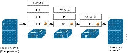
IP-in-IP encapsulation involves the insertion of an outer IP header over the existing IP header. The source and destination address in the outer IP header point to the endpoints of the IP-in-IP tunnel. The stack of IP headers is used to direct the packet over a predetermined path to the destination, provided the network administrator knows the loopback addresses of the routers transporting the packet. This tunneling mechanism can be used for determining availability and latency for most network architectures. It is to be noted that the entire path from source to the destination does not have to be included in the headers, but a segment of the network can be chosen for directing the packets.

In IP-in-IP encapsulation and decapsulation has two types of packets. The original IP packets that are encapsulated are called Inner packets and the IP header stack added while encasulation are called the Outer packets.


Note


The router only supports decapsulation and no encapsulation. Encapsulation is done by remote routers.


The following topology describes a use case where IP-in-IP encapsulation and decapsulation are used for different segments of the network from source to destination. The IP-in-IP tunnel consists of multiple routers that are used to decapsulate and direct the packet through the data center fabric network.

Figure 2. IP-in-IP Decapsulation Through a Data Center Network

The following illustration shows how the stacked IPv4 headers are decapsulated as they traverse through the decapsulating routers.

Figure 3. IP Header Decapsulation

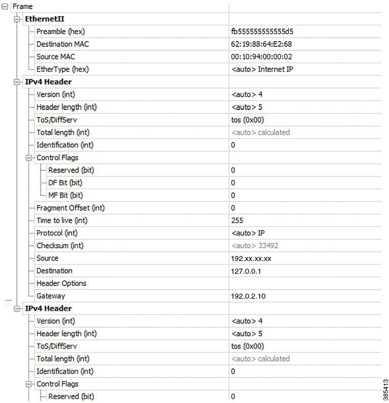
Stacked IP Header in an Encapsulated Packet

The encapsulated packet has an outer IPv4 header that is stacked over the original IPv4 header, as shown in the following illustration.

Figure 4. Encapsulated Packet

Configuration

You can use the following sample configuration in the routers to decapsulate the packet as it traverses the IP-in-IP tunnel:


Router(config)# interface loopback 0
Router(config-if)# ipv4 address 127.0.0.1/32
Router(config-if)# no shutdown
Router(config-if)# interface tunnel-ip 10
Router(config-if)# ipv4 unnumbered loopback 1
Router(config-if)# tunnel mode ipv4 decap 
Router(config-if)# tunnel source loopback 0
  • tunnel-ip: configures an IP-in-IP tunnel interface.

  • ipv4 unnumbered loopback address: enables ipv4 packet processing without an explicit address, except for loopback address.

  • tunnel mode ipv4 decap: enables IP-in-IP decapsulation.

  • tunnel source: indicates the source address for the IP-in-IP decap tunnel with respect to the router interface.


Note


You can configure the tunnel destination only if you want to decapsulate packets from a particular destination. If no tunnel destination is configured, then all the ip-in-ip ingress packets on the configured interface are decapsulated.


Running Configuration

Router# show running-config interface tunnel-ip 10
...
interface tunnel-ip 10
ipv4 unnumbered loopback 1
tunnel mode ipv4 decap

Extended ACL to Match the Outer Header for IP-in-IP Decapsulation

Starting with Cisco IOS XR Software Release 7.0.14, extended ACL has to match on the outer header for IP-in-IP Decapsulation. Extended ACL support reduces mirrored traffic throughput. This match is based only on the IPv4 protocol, and extended ACL is applied to the received outermost IP header, even if the outer header is locally terminated.

Sample configuration:

Router#show running-config interface bundle-Ether 50.5
Tue May 26 12:11:49.017 UTC
interface Bundle-Ether50.5
ipv4 address 101.1.5.1 255.255.255.0
encapsulation dot1q 5
ipv4 access-group ExtACL_IPinIP ingress
ipv4 access-group any_dscpegg egress
!
Router#show access-lists ipv4 ExtACL_IPinIP hardware ingress location$
Tue May 26 12:11:55.940 UTC
ipv4 access-list ExtACL_IPinIP
10 permit ipv4 192.168.0.0 0.0.255.255 any ttl gt 150
11 deny ipv4 172.16.0.0 0.0.255.255 any fragments
12 permit ipv4 any any

Decapsulation using tunnel source direct

Table 9. Feature History Table

Feature Name

Release Information

Feature Description

Decapsulation using tunnel source direct

Release 25.1.1

Introduced in this release on: Fixed Systems (8010 [ASIC: A100])(select variants only*)

*This feature is supported on Cisco 8011-4G24Y4H-I routers.

Decapsulation using tunnel source direct

Release 24.4.1

Introduced in this release on: Fixed Systems (8200 [ASIC: P100], 8700 [ASIC: P100, K100])(select variants only*); Modular Systems (8800 [LC ASIC: P100])(select variants only*)

*This feature is now supported on:

  • 8212-48FH-M

  • 8711-32FH-M

  • 8712-MOD-M

  • 88-LC1-12TH24FH-E

  • 88-LC1-36EH+A8:B12

  • 88-LC1-52Y8H-EM

Decapsulation using tunnel source direct

Release 7.5.3

Tunnel source direct allows you to decapsulate the tunnels on any L3 interface on the router.

You can use the tunnel source direct configuration command to choose the specific IP Equal-Cost Multipath (ECMP) links for troubleshooting, when there are multiple IP links between two devices.

To debug faults in various large networks, you may have to capture and analyze the network traffic at a packet level. In datacenter networks, administrators face problems with the volume of traffic and diversity of faults. To troubleshoot faults in a timely manner, DCN administrators must identify affected packets inside large volumes of traffic. They must track them across multiple network components, analyze traffic traces for fault patterns, and test or confirm potential causes.

In some networks, IP-in-IP decapsulation is currently used in network management, to verify ECMP availability and to measure the latency of each path within a datacenter.

The Network Management System (NMS) sends IP-in-IP (IPv4 or IPv6) packets with a stack (multiple) of predefined IPv4 or IPv6 headers (device IP addresses). The destination device at each hop removes the outside header, performs a lookup on the next header, and forwards the packets if a route exists.

Using the tunnel source direct command, you can choose the specific IP Equal-Cost Multipath (ECMP) links for troubleshooting, when there are multiple IP links between two devices.


Tip


You can programmatically configure and manage the Ethernet interfaces using openconfig-ethernet-if.yang and openconfig-interfaces.yang OpenConfig data models. To get started with using data models, see the Programmability Configuration Guide for Cisco 8000 Series Routers.


Guidelines and Limitations

The following guidelines are applicable to this feature.

  • The tunnel source direct command is only compatible with 'tunnel mode decap' for IP-in-IP decapsulation.

  • The source-direct tunnel is always operationally up unless it is administratively shut down. The directly connected interfaces are identified using the show ip route direct command.

  • All Layer 3 interfaces that are configured on the device are supported.

  • Platform can accept and program only certain number of IP addresses. The number of IP addresses depends on the make of the platform linecard (LC). Each LC can have different number of Network Processor (NP) slices and interfaces.

  • Only one source-direct tunnel per address-family is supported for configuration.

  • Source-direct and regular decap tunnels can't co-exist for a specific address-family. Any configuration that attempts to enable both is automatically rejected, and an error message is displayed to indicate the conflict.

  • Inline modification of an existing regular decap tunnel (tunnel source interface| IP address ) to a source-direct tunnel (tunnel source direct ), or changing a source-direct tunnel to a regular decap tunnel, is not supported. Commit-replace may fail if the same tunnel-id is used as part of the commit-replace operation. You must delete the tunnel and recreate it.

The following functionalities are not supported for the tunnel source direct option.

  • GRE tunneling mode.

  • VRF (only default VRF is supported).

  • ACL and QoS on the tunnels.

  • Tunnel encapsulation.

  • Tunnel NetIO DLL: Decapsulation is not supported if the packet is punted to slow path.

Configure Decapsulation Using Tunnel Source Direct

Configuration

The tunnel source direct configures IP-in-IP tunnel decapsulation on any directly connected IP addresses. This option is now supported only when the IP-in-IP decapsulation is used to source route the packets through the network.

This example shows how to configure IP-in-IP tunnel decapsulation on directly connected IP addresses:

Router# configure terminal
Router(config)#interface Tunnel4
  Router(config)#tunnel mode ipv4 decap
  Router(config)#tunnel source direct
  Router(config)#no shutdown

This example shows how to configure IP-in-IP tunnel decapsulation on IPv6 enabled networks:

Router# configure terminal
Router(config)#interface Tunnel6
  Router(config)#tunnel mode ipv6 decap
  Router(config)#tunnel source direct
  Router(config)#no shutdown
Verifying the Configuration

The following example shows how to verify IP-in-IP tunnel decapsulation with tunnel source direct option:

Router#show running-config interface tunnel 1
interface Tunnel1
  tunnel mode ipv6ipv6 decapsulate-any
  tunnel source direct
  no shutdown

Router#show interface tunnel 1
Tunnel1 is up    Admin State: up    
MTU 1460 bytes, BW 9 Kbit    
Tunnel protocol/transport IPv6/DECAPANY/IPv6    
Tunnel source - direct     
Tx    0 packets output, 0 bytes    Rx    0 packets input, 0 bytes

Configure Tunnel Destination with an Object Group

Table 10. Feature History Table

Feature Name

Release Information

Description

Configure Tunnel Destination with an Object Group

Release 7.5.4

You can now assign an object group as the destination for an IP-in-IP decapsulation tunnel. With this functionality, you could configure an IPv4 or IPv6 object group consisting of multiple IPv4 or IPv6 addresses as the destination for the tunnel instead of a single IPv4 or IPv6 address. Using an object group instead of a singular IP address. This helps reduce the configuration complexity in the router by replacing the multiple tunnels with one destination with a single decapsulation tunnel that supports a diverse range of destinations

The feature introduces these changes:

  • CLI: New tunnel destination command.

  • YANG Data Model: New object-group option supported in Cisco-IOS-XR-um-if-tunnel-cfg.yang Cisco native model (see GitHub).

In IP-in-IP Decapsulation, the router accepts a packet on a tunneled interface only when the tunnel IP address matches the source IP address of the incoming packets. With this implementation, the user needs to configure separate interface tunnels for each IP address that the router needs to receive the traffic packets. This limitation often leads to configuration overload on the router.

You can eliminate the configuration overload on the router by assigning an object group as the tunnel destination for IPv4 and IPv6 traffic types. That is, the router matches the source IP address of the incoming packet against the object group available as the tunnel destination. The decapsulation tunnel accepts the incoming traffic packets when there’s a match between the packet source and the object group. Otherwise, the router drops the packets.

Restrictions

The following restrictions are applicable to the tunnel destination with an object group feature:

  • GRE tunnels don’t support configuring object groups as the tunnel destination.

  • The router supports configuring tunnel destination with an object group only when the tunnel source is tunnel source direct.

  • You can configure the object group as tunnel destination only on default VRF.

  • Configuring object groups as the tunnel destination isn’t applicable to tunnel encapsulation.

  • Subinterfaces don’t support configuring object groups as the tunnel destination.

  • Configuring object groups as the tunnel destination feature is mutually exclusive with ACL and QoS features.

  • The tunnel destination feature supports only IPv4 and IPv6 object groups.

  • The router does not support changing tunnel configuration after its creation. Configure the tunnel source direct and tunnel destination with an object group while creating the tunnel only.

Prerequisites

Configuration example

This section provides an example for configuring the tunnel destination with an object group.

IPv4 configuration

Router# configure
/* Configure the IPv4 object group */
Router(config)# object-group network ipv4 Test_IPv4 
Router(config-object-group-ipv4)# 192.0.2.0/24
Router(config-object-group-ipv4)# 198.51.100.0/24
Router(config-object-group-ipv4)# 203.0.113.0/24
Router(config-object-group-ipv4)# commit
Router(config-object-group-ipv4)# exit

/* Enters the tunnel configuration mode */
Router(config)# interface tunnel-ip 1

/* Configures the tunnel mode */
Router(config-if)# tunnel mode ipv4 decap 

/* Configures the tunnel to accept all packets with destination address matching the IP addresses on the router */
Router(config-if)# tunnel source direct

/* Configures the destination of the tunnel as the defined object-group */
Router(config-if)# tunnel destination object-group ipv4 Test_IPv4

Router(config-if)# no shutdown
Router(config-if)# commit
Router(config-if)# exit

IPv6 configuration

Router# configure
/* Configure the IPv6 object group */
Router(config)# object-group network ipv6 Test_IPv6 
Router(config-object-group-ipv6)# 2001:DB8::/32
Router(config-object-group-ipv6)# 2001:DB8::/48
Router(config-object-group-ipv6)# commit
Router(config-object-group-ipv6)# exit

/* Enters the tunnel configuration mode */
Router(config)# interface tunnel-ip 2

/* Configures the tunnel mode */
Router(config-if)# tunnel mode ipv6 decap

/* Configures the tunnel to accept all packets with destination address matching the IP addresses on the router */
Router(config-if)# tunnel source direct

/* Configures the destination of the tunnel as the defined object-group */
Router(config-if)# tunnel destination object-group ipv6 Test_IPv6

Router(config-if)# no shutdown
Router(config-if)# commit
Router(config-if)# exit

Running Configuration

Router# show running-config object-group
object-group network ipv4 Test_IPv4
 192.0.2.0/24
 198.51.100.0/24
 203.0.113.0/24
!
object-group network ipv6 Test_IPv6
 2001:DB8::/32
 2001:DB8::/48
!
Router#show running-config interface tunnel-ip 1
interface tunnel-ip1
 tunnel mode ipv4 decap
 tunnel source direct
 tunnel destination object-group ipv4 Test_IPv4
!
Router#show running-config interface tunnel-ip 2
Fri Nov 29 11:26:54.716 UTC
interface tunnel-ip2
 tunnel mode ipv6 decap
 tunnel source direct
 tunnel destination object-group ipv6 Test_IPv6
!

Verification

Router# show tunnel ip ea database	

----- node0_0_CPU0 -----
tunnel ifhandle 0x80022cc
tunnel source 161.115.1.2
tunnel destination address group Test_IPv4
tunnel transport vrf table id 0xe0000000
tunnel mode gre ipv4, encap
tunnel bandwidth 100 kbps
tunnel platform id 0x0
tunnel flags 0x40003400
IntfStateUp
BcStateUp
Ipv4Caps
Encap
tunnel mtu 1500
tunnel tos 0
tunnel ttl 255
tunnel adjacency flags 0x1
tunnel o/p interface handle 0x0
tunnel key 0x0, entropy length 0 (mask 0xffffffff)
tunnel QT next 0x0
tunnel platform data (nil)
Platform:
Handle: (nil)
Decap ID: 0
Decap RIF: 0
Decap Recycle Encap ID: 0x00000000
Encap RIF: 0
Encap Recycle Encap ID: 0x00000000
Encap IPv4 Encap ID: 0x4001381b
Encap IPv6 Encap ID: 0x00000000
Encap MPLS Encap ID: 0x00000000
DecFEC DecRcyLIF DecStatsId EncRcyLIF

Hashing for load balancing

Hashing is a technique used by network devices such as routers and switches to distribute traffic flows or packets efficiently across multiple available paths, links, or resources. Hashing technique

  • ensures all packets from the same traffic flow (e.g., TCP connection) follow the same path, avoiding out-of-order delivery

  • distributes multiple traffic flows across all paths thus preventing overload of any single path, and

  • works automatically as paths or links are added or removed.

How hashing works

  1. Field extraction:

    The device extracts certain fields from the packet header (e.g., source/destination IP addresses, ports, protocol).

  2. Hash function:

    These fields are combined and fed into a mathematical function called a hash function. This function produces a fixed-size output known as the hash value.

  3. Path selection:

    The resulting hash value is used to select one of several possible paths, links, or next hops. For example, if there are 4 links in a bundle, the device might use:

    path = hash_value % 4

    Here, % indicates the modulus operation.

If multiple routers use the same hash algorithm and field selection, the same flows may be mapped to the same paths on each router, resulting in polarization. This can lead to uneven traffic distribution and underused network capacity.

By increasing the variety of hash profiles (using techniques like field duplication and masking), each router hashes differently thus reducing the chance of polarization and improving overall load balancing. For more information on the field duplication and masking technique, see Dupe and mask technique for user-defined fields.

Configure ECMP or SPA seed value

These commands configure seed values for ECMP (Equal-Cost Multi-Path) and SPA (likely Strict Priority Algorithm or a similar internal load-balancing component) hashing. Seed values introduce an additional element of randomness into the hashing process, further helping to de-correlate flows and prevent polarization.

Procedure


Step 1

Configure the seed value for ECMP and SPA using these commands:

  • Set a specific hexadecimal seed value (0xaa in this example) for the ECMP hashing algorithm across the entire chassis.

    Router# config
    Router (config)# cef platform load-balancing algorithm adjust ecmp-seed 0xaa
    

    This seed helps ensure that traffic is distributed consistently and without bias across multiple equal-cost paths, preventing polarization.

  • Set a specific hexadecimal seed value (0xbb in this example) for the SPA hashing algorithm across the entire chassis.

    Router# config
    Router (config)# cef platform load-balancing algorithm adjust spa-seed 0xbb
    

    This seed is incorporated into the hashing calculation to add an element of uniqueness, which can help distribute traffic more evenly across multiple paths.

  • Set a specific hexadecimal seed value (0xdd in this example) for the ECMP hashing algorithm on a particular NPU instance.

    Router# config
    Router (config)# cef platform load-balancing algorithm adjust ecmp-seed 0xdd instance 0 location 0/0/CPU0
    

    This provides NPU-specific control over the ECMP hashing randomness, which can be beneficial in complex network designs.

  • Set a specific hexadecimal seed value (0xcc in this example) for the SPA hashing algorithm on a particular NPU instance.

    Router# config
    Router (config)# cef platform load-balancing algorithm adjust spa-seed 0xcc instance 0 location 0/0/CPU0
    

    This allows for fine-grained control, enabling different NPUs to use distinct SPA seed values if their traffic patterns or load-balancing requirements differ.

Step 2

Execute this debug command that returns hash rotate and seed values programmed in NPU.

Example:

Router# show controllers npu debugshell 0 "script lb_hash_info hash_rotate_seed_val_all_np" location 0/0/CPU0
Tue May 20 13:36:55.158 EDT
Node ID: 0/0/CPU0
Executing User File: /pkg/bin/device_hash_rotate_info.py
Hash Rotate Value and seed value in HW for NPU: 0
=================================================
Load_Balancing_node_id: 21	                  >>>>>>>>>> (Load balancing node ID derived from XR hash rotate)
XR Hash Rotate: 20 			       >>>>>>>>>> Hash-rotate value set by either system or user (1-143)
ECMP seed value: 0xdd		                  >>>>>>>>>> ECMP seed value set by either system or user (0-0xffff)	
SPA seed value: 0xcc  	                  >>>>>>>>>> SPA seed value set by either system or user (0-0xffff)
Profile Group base value: 0 	                  >>>>>>>>>> Profile# used as part of increased overall hash rotate values

Configure hash rotation (node id) value

These configurations control the node-id (also referred to as HASH_ROTATE), which influences how the hashing algorithms process input fields, effectively reordering them to de-correlate flows. This is a mechanism to combat polarization.

Procedure


Step 1

Configure hash rotation value using one of these options.

  • Set a specific node-id (hash rotation value) for the entire chassis.

    Router# config
    Router (config)# cef platform load-balancing algorithm adjust 10
    

    The node-id determines one of the 216 (or more, with extended-entropy) possible permutations of input fields for the hashing algorithm. A specific value might be chosen to optimize load balancing for a known network topology or to address observed polarization issues.s

  • Set a specific node-id (hash rotation value) for a particular NPU instance on a specific line card, location 0/0/CPU0 and instance 0 to identify the NPU.

    Router# config
    Router (config)# cef platform load-balancing algorithm adjust 20 instance 0 location 0/0/CPU0
    

    This provides granular control, allowing different NPUs within the same chassis to use distinct hash rotation values, which can be useful in complex scenarios where traffic characteristics vary significantly across different NPU-handled interfaces.

  • Enable the system to automatically determine and set the node-id (hash rotation value) globally for the entire chassis.

    Router# config
    Router (config)# cef platform load-balancing algorithm adjust auto-global
    

    Note


    This configuration as it aims to dynamically select an optimal node-id to improve load balancing and minimize polarization without requiring manual intervention.

  • Enable the system to automatically determine and set the node-id (hash rotation value) for each individual NPU instance across all NPUs in the chassis.

    Router# config
    Router (config)# cef platform load-balancing algorithm adjust auto-instance
    

    This allows each NPU to independently optimize its hash rotation based on its specific traffic load and characteristics

Step 2

Execute this debug command that returns hash rotate and seed values programmed in NPU.

Example:

Router# show controllers npu debugshell 0 "script lb_hash_info hash_rotate_seed_val_all_np" location 0/0/CPU0
Tue May 20 13:36:55.158 EDT
Node ID: 0/0/CPU0
Executing User File: /pkg/bin/device_hash_rotate_info.py
Hash Rotate Value and seed value in HW for NPU: 0
=================================================
Load_Balancing_node_id: 21	                  >>>>>>>>>> (Load balancing node ID derived from XR hash rotate)
XR Hash Rotate: 20 			       >>>>>>>>>> Hash-rotate value set by either system or user (1-143)
ECMP seed value: 0xdd		                  >>>>>>>>>> ECMP seed value set by either system or user (0-0xffff)	
SPA seed value: 0xcc  	                  >>>>>>>>>> SPA seed value set by either system or user (0-0xffff)
Profile Group base value: 0 	                  >>>>>>>>>> Profile# used as part of increased overall hash rotate values

Dupe and mask technique for user-defined fields

A dupe and mask technique is a packet header hash optimization method that

  • duplicates selected user-defined fields from a packet header

  • applies masking to specific bits of the duplicated fields based on pre-defined profiles, and

  • enables routers to generate thousands of unique hash functions.

Table 11. Feature History Table

Feature Name

Release Information

Description

Dupe and mask of user-defined header fields

Release 25.4.1

Introduced in this release on: Fixed Systems (8200 [ASIC: Q200]); Centralized Systems (8600 [ASIC:Q200]) ; Modular Systems (8800 [LC ASIC: Q200])

This feature significantly reduces the risk of traffic polarization thus ensuring more even and efficient distribution of traffic across multiple network paths in large-scale networks.

The dupe and mask capability on certain user-defined header fields allows thousands of unique hash function selections.

The feature is supported on Cisco SiliconOne Q200-based systems.

This feature introduces these changes:

CLI: A new keyword, extended-entropy, has been added to the cef platform load-balancing command.

In large-scale networks, optimal load balancing is critical. Routers use hash algorithms to distribute traffic flows across multiple paths. However, if the hashing functions on consecutive routers are too similar, this can cause polarization—many flows get mapped to the same path on multiple routers, reducing network efficiency and resilience.

From Cisco IOS XR 25.4.1, the router supports the dupe and mask feature that duplicates and masks specific packet header fields such as IP addresses and port numbers to create thousands of unique hash function combinations. A new extended-entropy keyword has been added to the cef platform load-balancing command to configure the extended entropy.

The dupe and mask capability creates up to 256 extended entropy profiles based on router ID and combines these profiles with existing hashing options such as field reordering, algorithm selection, and so on to reach thousands of hash combinations.

By duplicating and masking certain input fields such as inner or outer IP addresses and port numbers, the effective number of unique hashing profiles or node-ids can be greatly increased—from 216 to potentially thousands (e.g., 36 hash rotates × 6 swizzle profiles × 256 dupe/mask profiles = 5,536 total). This is especially useful for complex data center and WAN scenarios, ensuring better traffic distribution even as flows traverse multiple routers.

By applying various combinations of duplication and masking to key packet header fields, the router can produce many unique hash inputs that effectively creates distinct ways in many folds to split up traffic flows, making it highly unlikely that two routers will hash traffic in the same way—thus preventing polarization and ensuring more balanced use of all network paths.

Benefits of field duplication and masking

These are some benefits of the dupe and mask feature for user-defined packet header fields:

  • Reduces risk of traffic polarization—Improves traffic distribution across paths and devices, even with random node-id assignments.

  • Scalable—Suitable for very large, multi-router, multi-path networks.

  • Flexible—Supports a range of configurations and traffic types.

Restrictions for dupe and mask technique

  • Supported only on Cisco Silicon One Q200-based systems.

  • Not compatible with the underlay dupe and mask feature.

  • Tunnel mode should be set to overlay mode.

  • Supported only on specific software and hardware versions; Incompable combinations are not allowed at the CLI.

Configure extended entropy profile

These configurations are introduced as part of the dupe and mask technique described in the document, which significantly increases the number of uncorrelated hash selection algorithms by modifying how input fields are processed.

Procedure

Step 1

Configure the extended entropy profile using one of these commands:

  • Enable the system to automatically select the most suitable extended entropy profile globally for the entire chassis.

    Router# config
    Router (config)# cef platform load-balancing extended-entropy auto-global
    
    This is the recommended option, as it allows the system to intelligently adapt and apply the dupe and mask technique to achieve optimal load balancing and minimize polarization without manual configuration of specific profiles
  • Enables the system to automatically select the most suitable extended entropy profile for each individual NPU instance across all NPUs in the chassis.

    Router# config
    Router (config)# cef platform load-balancing extended-entropy auto-instance
    

    This provides NPU-level optimization, allowing each NPU to dynamically choose a profile that best suits the traffic it is processing, further enhancing load balancing and polarization avoidance.

  • Selects a specific extended entropy profile (identified by profile-index 10 in this example) to be used for hashing across the entire chassis.

    Router# config
    Router (config)# cef platform load-balancing extended-entropy profile-index 10
    

    These profiles define how dupe and mask operations are applied to various header fields (like inner source/destination IP, TCP/UDP ports) to maximize entropy and de-correlation. This allows an administrator to explicitly choose a profile optimized for a particular traffic mix or to address specific polarization issues.

Step 2

Execute this command to verify the configuration for the IPv6 over IPv4 profile.

Example:
RP/0/RP0/CPU0:df3r001.lab18#show controllers npu debugshell 0 'script lb_hash_info dump_polarization_info_all_np' location 0/0/CPU0          	
Thu Jul 24 20:28:28.043 UTC

#Configured values
la_lb_packet_format_type_e_IPV4_NON Offset: 18 Width: 32 Offset: 20 Width: 24
la_lb_packet_format_type_e_IPV4_L4 Offset: 18 Width: 32 Offset: 20 Width: 24
la_lb_packet_format_type_e_IPV4_IPV4 Offset: 17 Width: 32 Offset: 16 Width: 24
la_lb_packet_format_type_e_IPV4_IPV6 Offset: 4 Width: 20 Offset: 17 Width: 25
la_lb_packet_format_type_e_IPV6_NON Offset: 4 Width: 20 Offset: 17 Width: 25
la_lb_packet_format_type_e_IPV6_L4 Offset: 4 Width: 20 Offset: 17 Width: 25
la_lb_packet_format_type_e_IPV6_IPV4 Offset: 17 Width: 32 Offset: 16 Width: 24
la_lb_packet_format_type_e_IPV6_IPV6 Offset: 4 Width: 20 Offset: 17 Width: 25
la_lb_packet_format_type_e_ETHERNET_NON_VLAN Offset: 0 Width: 0 Offset: 0 Width: 0
la_lb_packet_format_type_e_ETHERNET_VLAN Offset: 0 Width: 0 Offset: 0 Width: 0
la_lb_packet_format_type_e_ETH_IPV4 Offset: 0 Width: 0 Offset: 0 Width: 0
la_lb_packet_format_type_e_ETH_IPV6 Offset: 0 Width: 0 Offset: 0 Width: 0

Here, Offset: 4 Width: 20 and Offset: 17 Width: 25 incidicate two sets of offset and width used for additional entropy from the inner header.

An offset of 4 bytes (32 bits) is at the end of the FLOW_LABEL field, and a width of 20 bits includes the complete flow-label (going backwards from LSB to MSB). For information on the IPv6 header fields, see Fields in a standard IPv6 header of 40 bytes or 320 bits.

An offset of 17 bytes (136 bits) is at end of the first octet of the 5th group in the IPv6 source address. For example, for an IPv6 source address, 1111 : 1111 : 1111 : 1111 : 1111 : 1111 : 1111 : 1111, the offset is highlighed:
1111 : 1111 : 1111 : 1111 : 1111 : 1111 : 1111 : 1111

Here, the width of 25 bits is highlighted:

 
0001 0001 0001 0001 : 0001 0001 0001 0001 : 0001 0001 0001 0001 : 0001 0001 0001 0001 
 0001 0001 0001 0001 : 0001 0001 0001 0001 : 0001 0001 0001 0001 : 0001 0001 0001 0001
Table 12. Fields in a standard IPv6 header of 40 bytes or 320 bits

Fields

IPv6 Header

VERSION

Version field (4 bits) [0-3]

TRAFFIC_CLASS

Traffic Class field (8 bits) [4-11]

FLOW_LABEL

Flow Label field (20 bits) [12-31]

PAYLOAD_LENGTH

Payload Length field (16 bits)[32-47]

NEXT_HEADER

Next Header field (8 bits)[48-55]

HOP_LIMIT

Hop Limit field (8 bits)[56-63]

SRP_IP

Source IP Address field (128 bits)[64-191]

DST_IP

Destination IP Address field (128 bits)[192-319]


ECMP Hashing Support for Load Balancing

The system inherently supports the n-tuple hash algorithm. The first inner header in the n-tuple hashing includes the source port and the destination port of UDP / TCP protocol headers.

The load balancing performs these functions:

  • Incoming data traffic is distributed over multiple equal-cost connections.

  • Incoming data traffic is distributed over multiple equal-cost connections member links within a bundle interface.

  • Layer 2 bundle and Layer 3 (network layer) load-balancing decisions are taken on IPv4, and IPv6. If it is an IPv4 or an IPv6 payload, then an n-tuple hashing is done.

  • An n-tuple hash algorithm provides more granular load balancing and used for load balancing over multiple equal-cost Layer 3 (network layer) paths. The Layer 3 (network layer) path is on a physical interface or on a bundle interface.

  • The n-tuple load-balance hash calculation contains:

    • Source IP address

    • Destination IP address

    • IP Protocol type

    • Router ID

    • Source port

    • Destination port

    • Input interface

    • Flow-label (for IPv6 only)

User-defined fields for ECMP hashing

Table 13. Feature History Table

Feature Name

Release Information

Description

User-defined fields for ECMP hashing

Release 25.1.1

Introduced in this release on: Fixed Systems (8010 [ASIC: A100])(select variants only*)

*This feature is supported on Cisco 8011-4G24Y4H-I routers.

User-defined fields for ECMP hashing

Release 24.4.1

Introduced in this release on: Fixed Systems (8200 [ASIC: P100], 8700 [ASIC: P100, K100])(select variants only*); Modular Systems (8800 [LC ASIC: P100])(select variants only*)

*This feature is now supported on:

  • 8212-48FH-M

  • 8711-32FH-M

  • 8712-MOD-M

  • 88-LC1-12TH24FH-E

  • 88-LC1-36EH

  • 88-LC1-52Y8H-EM

User-defined fields for ECMP hashing

Release 24.2.11

We ensure that in cases where multiple paths are used to carry packets from source to destination, each path is utilized for this purpose and no path is over-utilized or congested. This is made possible because we now provide customized ECMP hashing fields that are used for path computation.

Previously, the router relied on fixed packet header fields for hashing, which were not user configurable. With additional user-defined bytes considered for hashing, the granularity at which the traffic can be analyzed for ECMP load balancing increases, resulting in better load balancing and path utilization.

The feature introduces these changes:

CLI:

YANG:

ECMP hashing is used to distribute traffic across multiple equal-cost paths. See ECMP Hashing Support for Load Balancing for the default static hashing algorithm details.

You can now add user-defined packet header fields for ECMP path calculation for ipv4 and ipv6 flows using the cef load-balancing fields user-data command. Ensure you specify these user-defined fields based on the type of traffic flow that requires load balancing. You can include the following parameters:

  • Hash header: The hash header specifies which packet header is being considered for load balancing. You can enable any or all of the available six profiles.

    • IPv4: tcp, udp, non-tcp-udp

    • IPv6: tcp, udp, non-tcp-udp

    If any hash header profile is defined for load balancing, along with the fixed fields considered for hashing, additional bytes in the payload are also used for path computation.

  • Hashing offset: The hashing offset specifies the byte location from the end of the configured header.

  • Hash size: The hash size specifies the number of bytes that is considered from the start of the hash offset by the ECMP hashing algorithm. Range is 1 to 4 bytes.

  • Location: This specifies the location of the ingress line card that receives the incoming traffic. The user-defined hashing configuration is applied on the specified line card.

The addition of the user-defined packer header fields increases the granularity at which the traffic is analyzed for ECMP load balancing. When multiple paths with equal cost are available for routing a specific type of packet from a source to a destination, this granularity ensures that the intended type of traffic is evenly distributed across these paths. This ensures all available paths are used efficiently and prevents congestion or over-utilization of a single path.

You can also retrieve the exact-route information based on the configured user-data using the show cef exact-route command with user-data keyword.


Note


  • When the user-defined hashing configuration is active, any additional options or optional keywords are disregarded during the parsing of incoming packets for retrieving the user-defined bytes.

  • The hashing results based on user-defined hash feature is applicable to BGP/IGP ECMP and LAG hashing.

  • The use of the user-defined hashing configuration changes the load balancing behavior of GRE and IPinIP traffic. This includes all traffic that begins with ipv4, ipv6, ipv4+udp, ipv6+udp, ipv4+tcp, and ipv6+tcp, regardless of the payload.


Configure User-Defined Fields for ECMP Hashing

The command cef load-balancing fields user-data configures the additional user-defined fields that are to be considered for the hashing algorithm.

This example shows how to configure the additional IPv4 header fields for TCP packets:

Router# configure terminal
Router(config)#cef load-balancing fields user-data ipv4 tcp offset 5 size 3 location 0/0/CPU0
Router(config)#commit
  • offset 5: The payload considered for hashing starts from byte 6 from the end of TCP header.

  • size 3: Three bytes of payload are considered.

  • location 0/0/CPU0: Specifies the line card on which the configuration is applied.

In the above example, the sixth, seventh, and eighth bytes of the payload are considered additionally for the hashing.

This example shows how to configure the additional IPv6 header fields for UDP packets:

Router# configure terminal
Router(config)#cef load-balancing fields user-data ipv6 udp offset 0 size 2 location 0/0/CPU0
Router(config)#commit
  • offset 0: The payload considered for hashing starts from the end of UDP header.

  • size 2: Two bytes of payload are considered.

  • location 0/0/CPU0: Specifies the line card on which the configuration is applied.

In the above example, the first two bytes of payload of a UDP packet are considered additionally for the hashing.

Running Configuration

The following example shows the running configuration:

Router#show running-config | include cef
Fri Jul 28 12:02:01.002 UTC
cef load-balancing fields user-data ipv4 tcp offset 5 size 3 location 0/0/CPU0
cef load-balancing fields user-data ipv6 udp offset 0 size 2 location 0/0/CPU0
Router#

Verification

The following example shows the difference in load balancing before and after applying user-defined hashing, for a flow with data that exhibits good hashing behavior.

Before applying user-defined hashing
Router#show interfaces accounting | i IPV6_U
  Protocol              Pkts In         Chars In     Pkts Out        Chars Out
  IPV6_UNICAST                1               72            0                0
  IPV6_UNICAST                1               72            0                0
  IPV6_UNICAST                1               72            0                0
  IPV6_UNICAST                1               72            0                0
  IPV6_UNICAST                2              144            0                0
  IPV6_UNICAST                1               72            0                0
  IPV6_UNICAST                0                0      3979416       1981749168
  IPV6_UNICAST          4191438       2087336124            0                0
  IPV6_UNICAST                1               72            0                0
  IPV6_UNICAST                1               72            0                0
  IPV6_UNICAST                1               72            0                0
Router#
After applying user-defined hashing
Router#show interfaces accounting | i IPV6_U
  Protocol              Pkts In         Chars In     Pkts Out        Chars Out
  IPV6_UNICAST                0                0        39119         19481262
  IPV6_UNICAST                0                0        39801         19820898
  IPV6_UNICAST                0                0        40483         20160534
  IPV6_UNICAST                0                0        40524         20180952
  IPV6_UNICAST                0                0        40573         20205354
  IPV6_UNICAST                0                0        40614         20225772
  IPV6_UNICAST                0                0        39368         19605264
  IPV6_UNICAST                0                0        40734         20285532
  IPV6_UNICAST                0                0        40777         20306946
  IPV6_UNICAST                0                0        40171         20005158
  IPV6_UNICAST                0                0        40858         20347284
  IPV6_UNICAST                0                0        40269         20053962
  IPV6_UNICAST                0                0        41603         20718294
  IPV6_UNICAST                0                0        40363         20100774
  IPV6_UNICAST                0                0        40407         20122686
  IPV6_UNICAST                0                0        41098         20466804
  IPV6_UNICAST           850393        423495714            0                0

To view the exact route information allocated to the packets, use show cef exact-route command with user-data keyword.

The packet contains value 0x2 in the packet position for the ipv6 packet, for which the user-defined configuration has been added for a non-tcp-udp ipv6 flow.

Router#show cef ipv6 exact-route 100::10 60::1 flow-label 0 protocol 59 source-port 0 destination-port 0 user-data 0x2 ingress-interface HundredGigE0/0/0/2 location 0/0/cpu0
Unsupported protocol value 59
60::/16, version 1293, internal 0x1000001 0x20 (ptr 0x8b78ef00) [1], 0x400 (0x8e9cfc48), 0x0 (0x0)
 Updated Aug 14 07:50:20.022 
 local adjacency to Bundle-Ether3.30

 Prefix Len 16, traffic index 0, precedence n/a, priority 2
   via Bundle-Ether3.30
   via fe80::72b3:17ff:feae:d703/128, Bundle-Ether3.30, 7 dependencies, weight 0, class 0 [flags 0x0]
    path-idx 7 NHID 0x0 [0x8db8bed8 0x0]
    next hop fe80::72b3:17ff:feae:d703/128
    local adjacency