Geo-Redundancy deployment

Prerequisites for geo-redundancy

Before you enable GR between sites, complete these requirements:

  • Network Configuration: Configure the replication network VLAN on all master nodes at both sites.

  • IP Allocation: Allocate IP addresses based on the number of replica sets configured for both the MongoDB and CDL data-store endpoints.

  • Timing: Complete all network configurations and IP allocations before you enable GR to prevent replication issues.


Note


The number of MongoDB replica sets for each datastore endpoint determines the total number of IP addresses required for the deployment.


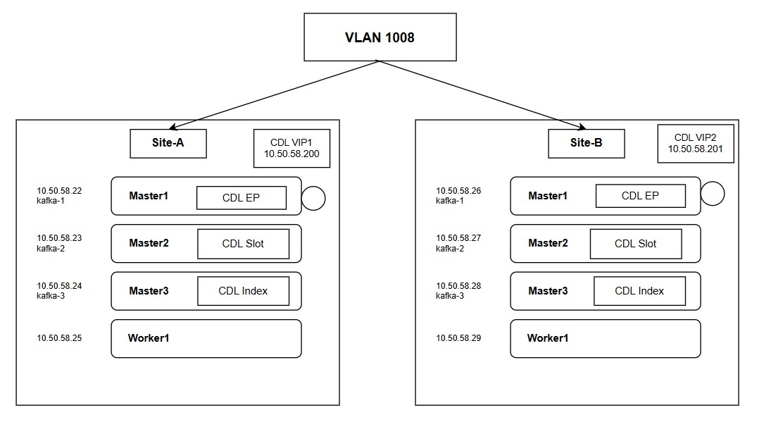
IP address allocation for datastore endpoints

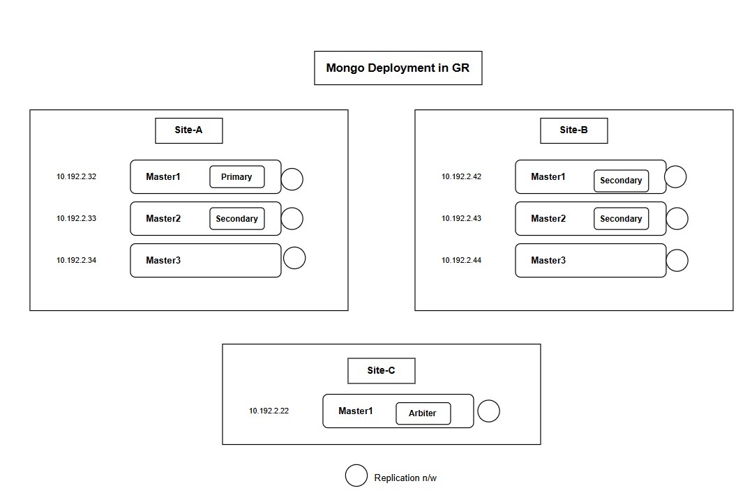
Deploy one MongoDB replica set with two local members and one CDL endpoint with three Kafka replicas. This configuration requires six IP addresses for the site.


Note


Configure three Kafka replicas on a single IP address and assign a unique port number to each replica. This approach reduces the total IP addresses required.


This table describes the IP address requirements for a single site in an active-active geo-redundant deployment.

Table 1. IP address requirements per site
Data store endpoint Number of IPs required Purpose Configuration reference
CDL endpoint VIP 1 Enables the remote site (Site-B) to access the local site (Site-A) CDL datastore for data synchronization. cdl datastore session endpoint external-ip 10.50.58.200
CDL Kafka replicas 3 Used for CDL replication. cdl kafka external-ip 10.50.58.22 10091
MongoDB members 2 Required for data members on each site. This assumes 2 MongoDB members per site and an arbiter placed at a third site. member-configuration member sdb-rs1-s1-m1 host 10.192.2.32

CDL configuration

Configure CDL replication network

Before you begin

This section provides the configuration steps and CLI examples to establish the CDL replication network across geographically redundant sites.

Configure the CDL replication network

Configure the replication VLAN and Virtual IP (VIP) on all master nodes at both sites. This configuration ensures data replication and successful VIP failover.

  • VLAN configuration: Configure the same replication VLAN on all nodes at both Site 1 (Gamma) and Site 2 (Delta).

  • Network segment: Ensure all IP addresses used for CDL and MongoDB reside on the same network segment. This ensures data replication and successful VIP failover.

Procedure


Step 1

Log in to the SMI cluster manager.

Step 2

Configure the replication VLAN on each master node for Site 1 (Gamma).

# Master 1
[cncps-gr-cm] SMI Cluster Deployer# show running-config clusters gamma nodes master-1 initial-boot netplan vlans vlan1008
clusters gamma
 nodes master-1
  initial-boot netplan vlans vlan1008
   dhcp4     false
   dhcp6     false
   addresses [ 192.0.2.22/24 ]
   id        1008
   link      bd2

# Master 2
[cncps-gr-cm] SMI Cluster Deployer# show running-config clusters gamma nodes master-2 initial-boot netplan vlans vlan1008
clusters gamma
 nodes master-2
  initial-boot netplan vlans vlan1008
   addresses [ 192.0.2.23/24 ]

# Master 3
[cncps-gr-cm] SMI Cluster Deployer# show running-config clusters gamma nodes master-3 initial-boot netplan vlans vlan1008
clusters gamma
 nodes master-3
  initial-boot netplan vlans vlan1008
   addresses [ 192.0.2.24/24 ]

Step 3

Configure the Virtual IP (VIP) for Site 1 (Gamma).

[cncps-gr-cm] SMI Cluster Deployer# show running-config clusters gamma virtual-ips
clusters gamma
 virtual-ips rep
  vrrp-interface vlan1008
  vrrp-router-id 208
  check-interface vlan2400
  exit
  ipv4-addresses 192.0.2.200
  mask      24
  broadcast 192.0.2.255
  device    vlan1010
  exit
  hosts master-1
   priority 100
  exit
  hosts master-2
   priority 100
  exit
  hosts master-3
   priority 100
  exit

Step 4

Configure the replication VLAN on each master node for Site 2 (Delta).

# Master 1
[cncps-gr-cm] SMI Cluster Deployer# show running-config clusters delta nodes master-1 initial-boot netplan vlans vlan1008
clusters delta
 nodes master-1
  initial-boot netplan vlans vlan1008
   dhcp4     false
   dhcp6     false
   addresses [ 198.51.100.26/24 ]
   id        1008
   link      bd2

# Master 2
[cncps-gr-cm] SMI Cluster Deployer# show running-config clusters delta nodes master-2 initial-boot netplan vlans vlan1008
clusters delta
 nodes master-2
  initial-boot netplan vlans vlan1008
   addresses [ 198.51.100.27/24 ]

# Master 3
[cncps-gr-cm] SMI Cluster Deployer# show running-config clusters delta nodes master-3 initial-boot netplan vlans vlan1008
clusters delta
 nodes master-3
  initial-boot netplan vlans vlan1008
   addresses [ 198.51.100.28/24 ]

Step 5

Configure the Virtual IP (VIP) for Site 2 (Delta).

[cncps-gr-cm] SMI Cluster Deployer# show running-config clusters delta virtual-ips
clusters delta
 virtual-ips rep
  vrrp-interface vlan1008
  vrrp-router-id 208
  check-interface vlan2400
  exit
  ipv4-addresses 198.51.100.201
  mask      24
  broadcast 198.51.100.255
  device    vlan1010
  exit
  hosts master-1
   priority 100
  exit
  hosts master-2
   priority 100
  exit
  hosts master-3
   priority 100
  exit

After completing these steps, the replication networks for CDL and MongoDB are successfully established and ready for data synchronization. Proceed to configure the application-level parameters in the CPC Ops-Center.

CDL replica configuration parameters for Geo-redundancy

Figure 1. Configure the CDL endpoint, slot, and index for GR deployment.

This table describes the replica configuration for each CDL component. These settings distribute data across multiple shards and nodes to enable high availability and write scalability.

Table 2.
Component Configuration reference Explanation
Slot Maps (4) cdl datastore session slot replica 2 slot map 4 Actual subscriber session data is stored and partitioned across 4 shards (maps), each with 2 copies for redundancy. This results in a total of 8 slot pods.
Index Maps (2) cdl datastore session index replica 2 index map 2 The index maps enable fast subscriber lookups by keys such as IP, MAC, or IMSI. The data is partitioned into 2 shards, each with 2 replicas, resulting in 4 index pods.
Endpoint Replicas (2) cdl datastore session endpoint replica 2 endpoint copies-per-node 1 Endpoint replicas provide gRPC API interfaces for applications to access CDL. The two replicas are distributed across different nodes to ensure service availability.

CDL configuration parameter definitions

These parameters are used to configure the Cisco Data Layer (CDL) for geographically redundant (GR) deployments:

Table 3.
Parameter Definition
external-services datastore Defines the Virtual IP (VIP) of the remote site.
cdl system-id The unique identification for the local site (for example, 1 for Site 1 and 2 for Site 2).
kafka-server The IP addresses of the Kafka servers located on the remote site.
cdl remote-site The system ID of the remote site (for example, 2 for Site 1).
geo-remote-site The system ID of the remote site used for data replication.
endpoint external-ip The Virtual IP (VIP) of the local site.
slot notification remote-system-id The system ID of the remote site used for notifications.
cdl kafka external-ip The IP addresses of the Kafka servers located on the local site.

Configure CDL for geo-redundancy

After completing the SMI Cluster Manager network setup, follow these steps to enable geo-replication for the CDL data layer.

Configure the CDL parameters on Site 1 and Site 2.

Procedure


Step 1

Configure CDL on Site 1:

  1. Log in to the CPC Ops-Center on Site 1 and enter the configuration mode.

  2. Replace the IP addresses in the example with the compliant addresses for your environment.

    Example:

    external-services datastore
      ips   [ 198.51.100.201 ]  ## Remote site CDL-VIP
      ports [ 8882 ]
    exit
    cdl system-id          1
    cdl node-type          session
    cdl enable-geo-replication true
    cdl zookeeper data-storage-size 1
    cdl zookeeper log-storage-size 1
    cdl zookeeper replica 3
    cdl zookeeper enable-JMX-metrics true
    cdl zookeeper enable-persistence false
    cdl remote-site 2
      db-endpoint host 198.51.100.201 ## Remote site CDL-VIP
      db-endpoint port 8882
      kafka-server 198.51.100.26 10091 ## Remote site Node-IP
      exit
      kafka-server 198.51.100.27 10092 ## Remote site Node-IP
      exit
      kafka-server 198.51.100.28 10093 ## Remote site Node-IP
      exit
    exit
    
    cdl datastore session
      cluster-id           1
      label-config         session
      geo-remote-site      [ 2 ]
      find-by-nuk-prefixes [ FramedIpKey MacAddressKey USuMSubscriberIdKey UserIdKey ]
      endpoint replica 2
      endpoint copies-per-node 1
      endpoint external-ip 192.0.2.200 ## Current site CDL-VIP
      index memory-limit 50072
      index replica 2
      index map    2
      slot memory-limit 50072
      slot replica 2
      slot map     4
      slot notification limit 25
      slot notification include-conflict-data true
      slot notification remote-system-id [ 2 ]
    exit
    cdl kafka replica 3
    cdl kafka storage 1
    cdl kafka label-config key smi.cisco.com/node-type-4
    cdl kafka label-config value session
    cdl kafka external-ip 192.0.2.22 10091 ## Current site kafka server IP
    exit
    cdl kafka external-ip 192.0.2.23 10092 ## Current site kafka server IP
    exit
    cdl kafka external-ip 192.0.2.24 10093 ## Current site kafka server IP
    exit
  3. commit the changes.

Step 2

Configure CDL on Site 2:

  1. Log in to the CPC Ops-Center on Site 2.

  2. Replace the IP addresses in the example with the compliant addresses for your environment.

    Example:

    external-services datastore
      ips   [ 192.0.2.200 ] ## Remote site CDL-VIP
      ports [ 8882 ]
    exit
    cdl system-id          2
    cdl node-type          session
    cdl enable-geo-replication true
    cdl zookeeper data-storage-size 1
    cdl zookeeper log-storage-size 1
    cdl zookeeper replica 3
    cdl zookeeper enable-JMX-metrics true
    cdl zookeeper enable-persistence false
    cdl remote-site 1
      db-endpoint host 192.0.2.200 ## Remote site CDL-VIP
      db-endpoint port 8882
      kafka-server 192.0.2.22 10091 ## Remote site Node-IP
      exit
      kafka-server 192.0.2.23 10092 ## Remote site Node-IP
      exit
      kafka-server 192.0.2.24 10093 ## Remote site Node-IP
      exit
    exit
    
    cdl datastore session
      cluster-id           1
      label-config         session
      geo-remote-site      [ 1 ]
      find-by-nuk-prefixes [ FramedIpKey MacAddressKey USuMSubscriberIdKey UserIdKey ]
      endpoint replica 2
      endpoint copies-per-node 1
      endpoint external-ip 198.51.100.201 ## Current site CDL-VIP
      index memory-limit 50072
      index replica 2
      index map    2
      slot memory-limit 50072
      slot replica 2
      slot map     4
      slot notification limit 25
      slot notification include-conflict-data true
      slot notification remote-system-id [ 1 ]
    exit
    cdl kafka replica 3
    cdl kafka storage 1
    cdl kafka label-config key smi.cisco.com/node-type-4
    cdl kafka label-config value session
    cdl kafka external-ip 198.51.100.26 10091 ## Current site kafka server IP
    exit
    cdl kafka external-ip 198.51.100.27 10092 ## Current site kafka server IP
    exit
    cdl kafka external-ip 198.51.100.28 10093 ## Current site kafka server IP
    exit
  3. commit the changes.


Verification commands

These commands helps to confirm that geographic synchronization is successful across clusters.

Pod status verification

Run these commands to confirm that the core CDL and infrastructure pods are working as expected.

Table 4. Pod status verification commands
Purpose Command
Verify all CDL pods kubectl get pods -n <namespace> | grep cdl
Check Kafka and Zookeeper kubectl get pods -n <namespace> | grep -E kafka|zookeeper
Check MirrorMaker kubectl get pods -n <namespace> | grep mirror

Note


The MirrorMaker pod begins running on both sites once all other pods are fully deployed. The pod remains not Ready until Site B is operational.


Replica count verification

Run these commands to verify the number of running replicas for endpoints, indexes, and slots. The output lists the Namespace in the first column and the Pod Name in the second column.

  1. CDL endpoint replicas

    kubectl get pods -A | grep cdl-ep

    Example

    CDL endpoint replicas
      NAMESPACE          POD NAME                                   STATUS   RESTARTS  AGE
    pcf-delta-cncps      cdl-ep-session-c1-d0-5b4c797d98-46dxf      1/1      Running   0   2d14h
    pcf-delta-cncps      cdl-ep-session-c1-d0-5b4c797d98-rhrkx      1/1      Running   0   2d14h
  2. CDL index map replicas

    kubectl get pods -A | grep cdl-index
    Example
    pcf-delta-cncps  cdl-index-session-c1-m1-0  1/1  Running  0  2d14h
    pcf-delta-cncps  cdl-index-session-c1-m1-1  1/1  Running  0  2d14h
    pcf-delta-cncps  cdl-index-session-c1-m2-0  1/1  Running  0  2d14h
    pcf-delta-cncps  cdl-index-session-c1-m2-1  1/1  Running  0  2d14h

    Note


    In the output, m1 and m2 indicate two instances. m1-0 and m1-1 indicate the two replicas of the m1 instance.


  3. CDL slot map replicas

    kubectl get pods -A | grep cdl-slot
    Example
    pcf-delta-cncps  cdl-slot-session-c1-m1-0  1/1  Running  0  2d14h
    pcf-delta-cncps  cdl-slot-session-c1-m1-1  1/1  Running  0  2d14h
    pcf-delta-cncps  cdl-slot-session-c1-m2-0  1/1  Running  0  2d14h
    pcf-delta-cncps  cdl-slot-session-c1-m2-1  1/1  Running  0  2d14h
    pcf-delta-cncps  cdl-slot-session-c1-m3-0  1/1  Running  0  2d14h
    pcf-delta-cncps  cdl-slot-session-c1-m3-1  1/1  Running  0  2d14h
    pcf-delta-cncps  cdl-slot-session-c1-m4-0  1/1  Running  0  2d14h
    pcf-delta-cncps  cdl-slot-session-c1-m4-1  1/1  Running  0  2d14h

Geo-synchronization verification

This procedure verifies geo-replication connectivity between CDL-EP pods and remote sites.

  1. Copy the Script from Utilities Pod.

  2. Copy the initiate_geo_sync.sh script from the utilities pod to the master node:

    kubectl cp -n <namespace> pcf-utilities-0:/data/utilities/support/script/initiate_geo_sync.sh initiate_geo_sync.sh
    Example
    kubectl cp -n pcf pcf-utilities-0:/data/utilities/support/script/initiate_geo_sync.sh initiate_geo_sync.sh
  3. Run the script with the required environment variables based on your IP configuration.

    1. For IPv6 remote sites:

      NAMESPACE="<your-namespace>" REMOTE_IP="<remote-ipv6-address>" IPFAMILY=6 ./initiate_geo_sync.sh
      Example
      cloud-user@master-1:~$ NAMESPACE="pcf-ns" REMOTE_IP="2001:db8::1" IPFAMILY=6 ./initiate_geo_sync.sh
      Defaulted container "ngn-datastore-ep" out of: ngn-datastore-ep, k8tz (init)
      2026/04/07 10:26:40 Geo sync is successful
      Defaulted container "ngn-datastore-ep" out of: ngn-datastore-ep, k8tz (init)
      2026/04/07 10:26:42 Geo sync is successful
      Cloud-user@master-1:~$
    2. For IPv4 remote sites:

      NAMESPACE="<your-namespace>" REMOTE_IP="<remote-ipv4-address>" ./initiate_geo_sync.sh
      Example
      cloud-user@master-1:~$ NAMESPACE="pcf-ns" REMOTE_IP="10.20.30.40" ./initiate_geo_sync.sh Defaulted container
       "ngn-datastore-ep" out of: ngn-datastore-ep, k8tz (init) 2026/04/07 10:26:40 Geo sync is successful Defaulted container
       "ngn-datastore-ep" out of: ngn-datastore-ep, 
      k8tz (init) 2026/04/07 10:26:42 Geo sync is successful

Note


For detailed debugging, enable debug mode:

DEBUG=true NAMESPACE="<your-namespace>" REMOTE_IP="<remote-ip>" IPFAMILY=6 ./initiate_geo_sync.sh

MongoDB SPR configuration

MongoDB SPR

MongoDB supports data replication between sites using both IPv4 and IPv6 networks. In a geographically redundant deployment, you configure MongoDB as a five-member or seven-member replica set.

The system distributes members across sites, and they communicate through the replication network. To ensure a majority vote during elections and prevent split-brain scenarios, it is recommend to deploy an arbiter member at a third independent site (Site 3).


Note


Configure each node hosting a Mongo member pod to use the replication network IP address. This setting enables communication between Mongo pods on the host and other members of the replica set. If you want to use IPv6 for the replication network, configure the host with the appropriate IPv6 address.


Figure 2. Mongo deployment in GR
MongoDB deployment guidelines

Review these deployment requirements before configuring the replica set:

  • Membership is not limited to master nodes. Any node in the cluster can host a MongoDB member.

  • Ensure that each node has the appropriate replica label key or value defined according to the replica set configuration.

  • Configure all nodes hosting MongoDB pods to use the replication network IP address (IPv4 or IPv6). This configuration enables communication between local pods and remote members of the replica set.

Configure MongoDB SPR for geo-redundancy

Procedure


Step 1

Log in to the CPC Ops-Center and enter config mode

Step 2

Configure the engine properties to enable subscriber hashing and cross-site searching. With these settings, the engine locates subscriber data across geo-redundant clusters.

Example:

Site 1 engine


engine pcf02production
properties balanceKeyHashAvpName
value SprKeyHash
exit
properties cc.ua.soap.url
value http://127.0.0.1:8080/apirouter
exit
properties maxHash
value 3
exit
properties queryEachSiteForSearchSubscribers
value true
exit
properties returnBalance
value false
exit
properties sprHashSupportEnabled
value true
exit
properties replaceFullNameInSearchSubscribers
value true
exit
exit

Example:

Site 2 engine

engine pcf02production
properties balanceKeyHashAvpName
value SprKeyHash
exit
properties cc.ua.soap.url
value http://127.0.0.1:8080/apirouter
exit
properties maxHash
value 3
exit
properties queryEachSiteForSearchSubscribers
value true
exit
properties returnBalance
value false
exit
properties sprHashSupportEnabled
value true
exit
properties replaceFullNameInSearchSubscribers
value true
exit
exit

Note


Update the Engine configuration when multiple SCDBs are configured. The API router configuration is required when the customer deploys more than one Mongo SPR replica set.

Step 3

Configure the MongoDB replica set across the GR cluster and the third site arbiter.

Example:

GR Site 1: SPR

db scdb replica-name sdb-spr01
port      65007
interface vlan2400
resource cpu limit 3000
resource memory limit 20000
replica-set-label key smi.cisco.com/node-type
replica-set-label value oam
member-configuration member sdb-rs1-s3-arbiter1
host    10.192.2.22  ##Remore site member IP
arbiter true
site    remote
exit
member-configuration member sdb-rs1-s1-m1
host     10.192.2.32 ##Local site member IP
arbiter false
priority 104
site     local
exit
member-configuration member sdb-rs1-s1-m2
host     10.192.2.33 ##Local site member IP
arbiter false
priority 103
site     local
exit
member-configuration member sdb-rs1-s2-m1
host     10.192.2.42 ##Remore site member IP
arbiter false
priority 102
site     remote
exit
member-configuration member sdb-rs1-s2-m2
host     10.192.2.43 ##Remore site member IP
arbiter false
priority 101
site     remote
exit
exit

Example:

GR Site2: SPR

db scdb replica-name sdb-spr01
port      65007
interface vlan2400
resource cpu limit 3000
resource memory limit 20000
replica-set-label key smi.cisco.com/node-type
replica-set-label value oam
member-configuration member sdb-rs1-s3-arbiter1
host    10.192.2.22 ##Remore site member IP
arbiter true
site    remote
exit
member-configuration member sdb-rs1-s1-m1
host     10.192.2.32 ##Remore site member IP
arbiter  false
priority 104
site     remote
exit
member-configuration member sdb-rs1-s1-m2
host     10.192.2.33 ##Remore site member IP
arbiter  false
priority 103
site     remote
exit
member-configuration member sdb-rs1-s2-m1
host     10.192.2.42 ##Local site member IP
arbiter  false
priority 102
site     local
exit
member-configuration member sdb-rs1-s2-m2
host     10.192.2.43 ##Local site member IP
arbiter  false
priority 101
site     local
exit
exit

Example:

GR Site 3 (third site arbiter): SPR

db scdb replica-name sdb-spr01
port      65007
interface vlan2400
resource cpu limit 3000
resource memory limit 20000
replica-set-label key smi.cisco.com/node-type
replica-set-label value oam
member-configuration member sdb-rs1-s3-arbiter1
host    10.192.2.22 ##Local member IP
arbiter true
site    local
exit
member-configuration member sdb-rs1-s1-m1
host     10.192.2.32 ##Remore site member IP
arbiter  false
priority 104
site     remote
exit
member-configuration member sdb-rs1-s1-m2
host     10.192.2.33 ##Remore site member IP
arbiter  false
priority 103
site     remote
exit
member-configuration member sdb-rs1-s2-m1
host     10.192.2.42 ##Remore site member IP
arbiter  false
priority 102
site     remote
exit
member-configuration member sdb-rs1-s2-m2
host     10.192.2.43 ##Remore site member IP
arbiter  false
priority 101
site     remote
exit
exit

Note


The third site arbiter should have the same replica set configuration as the other sites. In the configuration, label members located on remote sites will be labeled as "remote," except for the arbiter.

Step 4

Verify the replica set status from any cluster member: site 1, site 2, or the third site arbiter.

 show db scdb replica-set-status – cli output

Example:

db scdb replica-set-status

=======================================================================================================================================================================================================
HostName Port MemberName NodeName Priority State IsArbiter Replication-lag Site
(IP) Running Config From-Primary From-Member Running Config (Seconds)
=======================================================================================================================================================================================================
10.172.2.42 65004 sdb-rs1-s2-m1 delta-master-1 102 102 SECONDARY SECONDARY false false 0.0 remote
10.172.2.33 65004 sdb-rs1-s1-m2 gamma-master-2 103 103 SECONDARY SECONDARY false false 0.0 local
10.172.2.32 65004 sdb-rs1-s1-m1 gamma-master-1 104 104 PRIMARY PRIMARY false false 0.0 local
10.172.2.22 65004 sdb-rs1-s3-arbiter3 beta-master-1 0 ARBITER ARBITER true true N/A remote
10.172.2.43 65004 sdb-rs1-s2-m2 delta-master-2 101 101 SECONDARY SECONDARY false false 0.0 remote
=======================================================================================================================================================================================================

Policy Builder configuration

After you complete the initial CLI setup, configure the plugins in the Policy Builder. This enables the system to capture and store subscriber information in geographically redundant MongoDB replica sets. This configuration ensures that subscriber data is correctly partitioned. Data is accessible at both sites during normal operations and failover events.

Figure 3. USuM configuration

The USuM plugin must be configured to communicate with the MongoDB instances across both sites.

Field descriptions and settings

  • Primary Database IP

    Enter the IP address of the primary database node. This address must be identical for both Site 1 and Site 2 to ensure consistent data access.

  • Secondary Database IP

    Enter the IP address of the local secondary database node for the specific site you are configuring.


    Note


    Accessing the local secondary IP reduces latency during read operations and optimizes performance. This method also enables the system to access data if the replication link between the two sites fails.


Domain configuration

In a GR environment, the Domain configuration provides the critical connection between incoming network requests and the distributed database. The Domain configuration defines how the system identifies a subscriber and determines which database shard or site contains that subscriber's specific information.

The primary purpose of this configuration is to map incoming session identifiers (like a username or phone number) to a specific database lookup key. This ensures that the system queries the correct data store for subscriber profiles and session states in a multi-site or multi-shard environment.

Figure 4. Domain configuration

Field descriptions and settings

  • Domain Name

    • USuM Auth (or the specific name designated for your deployment).

      This is the unique identifier for the domain profile within the Policy Builder.

  • User Id Field

    • RADIUS Username.

      It specifies which attribute from the incoming RADIUS packet should be used as the primary key to identify the subscriber.

  • Remote Db Lookup Key Field:

    • NetworkId Hash Retriever.

      This is a critical setting for Geo-Redundancy. It instructs the system to use a hashing algorithm on the subscriber's ID to determine which database shard (e.g., sdb-spr01, sdb-spr02) holds the user's records. This setting ensures that the system locates data efficiently across different sites or shards in a distributed environment.

API router configuration

The API Router acts as a traffic controller within the CPC architecture. It is responsible for directing incoming requests to the specific database shard or replica set where the relevant subscriber data resides.


Note


This configuration is only required if your deployment utilizes multiple Session Control Database (SCDB) instances or multiple Subscriber Profile Repository (SPR) replica sets.


Figure 5. API router configuration

Field descriptions and settings

  • Filter Type

    • NetworkIdHash

    • The system uses this logic to categorize incoming requests. When NetworkIdHash, is selected, the system applies a mathematical hash to the subscriber's ID.

You have successfully configured geo-redundancy. The system is now ready for multi-site operations and data synchronization.