Basic Configuration
Before you begin using CPS vDRA, perform the following basic configurations in CPS DRA:
-
Configure Systems
-
Configure Diameter Application
-
Configure Routing AVP Definitions
Configure Systems
In CPS DRA, navigate to the System and Plugin Configuration.
Configure the stack in DRA Configuration plugin.
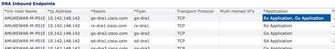
Configure the DRA Inbound Endpoints for incoming peer connections and DRA Outbound Endpoints for outgoing peer connection.
You can choose the Transport Protocol as TCP and SCTP depending on your requirement.
You can also specify the IPv4 or IPv6 address configuration for the stack connection.
The following image shows a sample configuration.
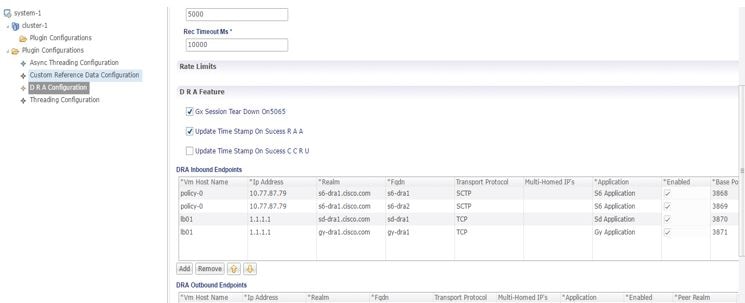
For more information, see DRA Configuration.
Configure Diameter Application
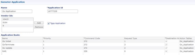
Configure the Diameter applications that are required to be connected over various interfaces with CPS vDRA.
The following image is a sample of a Gx application configuration:
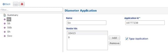
For more information, see Diameter Application.
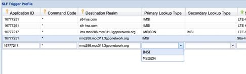
Configure Multiple Diameter Applications for a Peer Connection
Previously, vDRA supported a single application on a peer connection. In this release, vDRA supports multiple applications on a peer connection.
To configure multiple applications for a peer connection, go to vDRA Inbound Endpoints in DRA Plugin configuration. In the Applications field, select the button as shown:
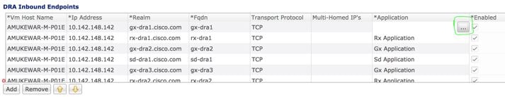
Select all the applications you require.
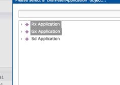
The following example shows multiple Diameter applications for a peer connection:
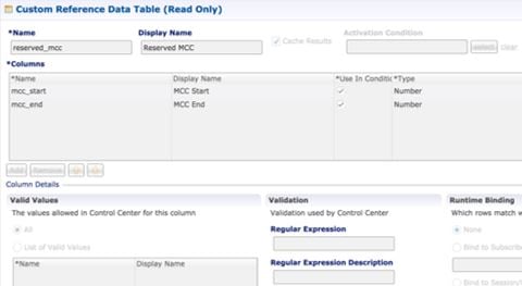
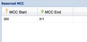
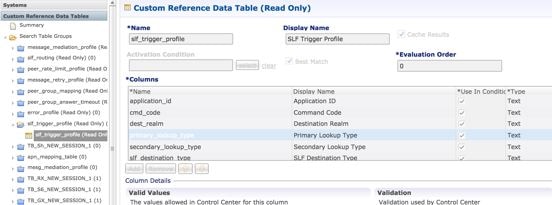
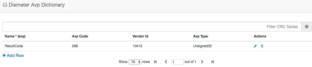
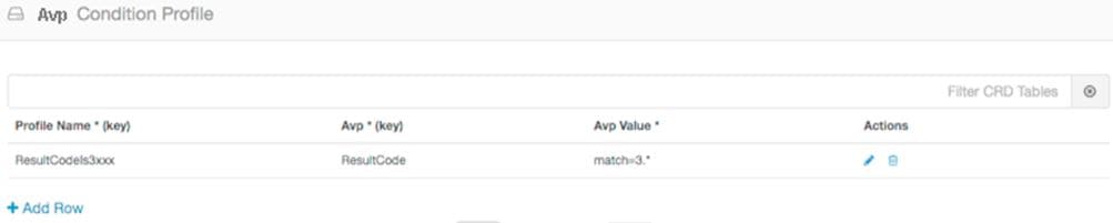
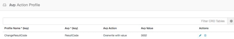
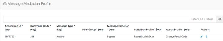
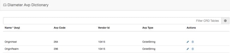
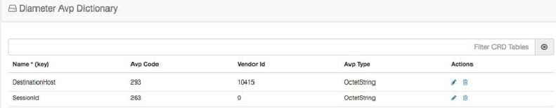
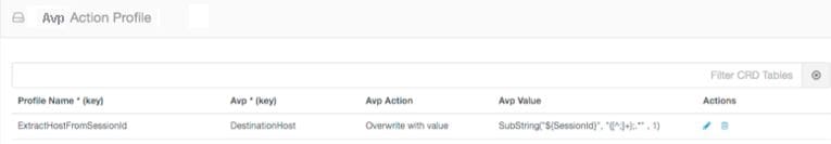
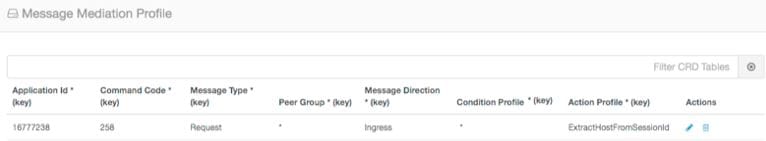
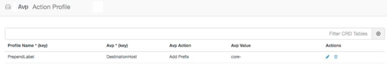
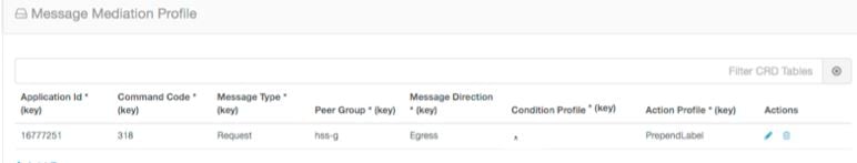
Configure Routing AVP Definitions
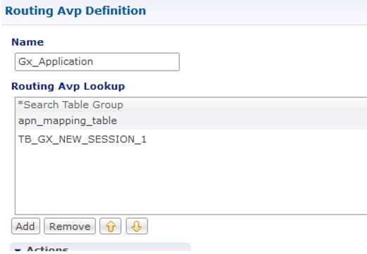
Configure the Routing AVP definitions to route calls on the basis of the AVPs that are present in diameter message.
In the Routing AVP Definition page, you specify the Application name and the table for table-driven routing.
In the Diameter Application page, configure the Application Route for table-driven routing.
The following screenshots show a sample configuration:
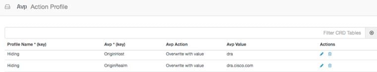
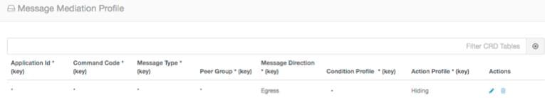
Enable Mediation
By default, mediation feature is disabled.
To enable the mediation, log in to Policy builder, select the “Enable Mediation” checkbox in .
Finally, publish the configuration changes.
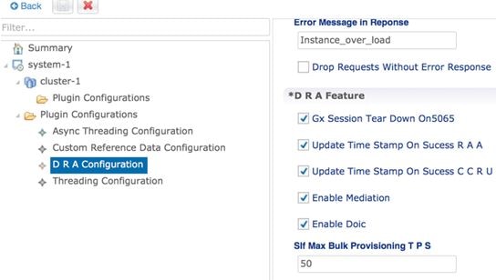
Enable DOIC
By default, DOIC feature is disabled.
To enable the DOIC, log in to Policy Builder, select the “Enable DOIC” checkbox in .
You must also enable DOIC for the group in Peer Group SRK Mapping table as described in Peer Group SRK Mapping.
Configure throttling using DOIC. For more information, see Configure Throttling of Diameter Messages Using DOIC.
Publish the configuration changes.
Configure Interfaces for SCTP Multi-homing
As a pre-requisite for SCTP multi-homing, you must first move the physical interfaces of Director VM inside the diameter-endpoint container.
To move the IPv4 interfaces, perform the following commands in vDRA Master CLI mode:
config diameter host dra-director-0-dra-director-52wumnq5l2yl
 interface ens3 ipv4 address 10.77.87.79 broadcast 10.77.87.255 prefix-length 24
diameter host dra-director-0-dra-director-52wumnq5l2yl interface ens3
route default gateway 10.77.87.1
diameter host dra-director-0-dra-director-52wumnq5l2yl interface ens5
 ipv4 address 10.225.115.199 broadcast 10.225.115.255 prefix-length 24
diameter host dra-director-0-dra-director-52wumnq5l2yl interface ens5
 route default gateway 10.225.115.1
To move the IPv6 interfaces, perform the following commands in vDRA Master CLI mode:
config diameter host dra-director-0-dra-director-52wumnq5l2yl
interface ens6 ipv6 address 2003:3051::114 prefix-length 64
diameter host dra-director-0-dra-director-52wumnq5l2yl interface
ens6 route default gateway 2003:3051::1
diameter host dra-director-0-dra-director-52wumnq5l2yl interface
ens7 ipv6 address 2003:3052::114 prefix-length 64
diameter host dra-director-0-dra-director-52wumnq5l2yl interface
ens7 route default gateway 2003:3052::1
Commit the configuration.


 Feedback