Plug-in Configuration
Cisco Policy Builder provides core plug-ins for customizing and optimizing your installation.
-
Configurations set at the system level are system-wide except as noted in the bullet items below.
-
Configurations set at the cluster level apply to that cluster and the instances in it. A value set here overrides the same value set at the system level.
-
Configurations set at the instance level apply to the instance only and override the same value set at the cluster or system level.
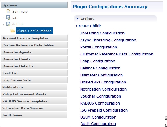
Select the Create Child action in a Plug-in Configuration node in the Systems tree to define them. You can change any of the variables from the default, or choose not to use a plug-in, as necessary.
When you create a system from the example, the following configuration stubs appear at the cluster and instance level:
Threading Configuration
A threading configuration utility is provided for advanced users.
Click Threading Configuration in the right pane to add the threading configuration to the system. If you are planning to run the system with higher TPS, then you need to configure Threading Configuration. For further information, contact your Cisco Technical Representative.
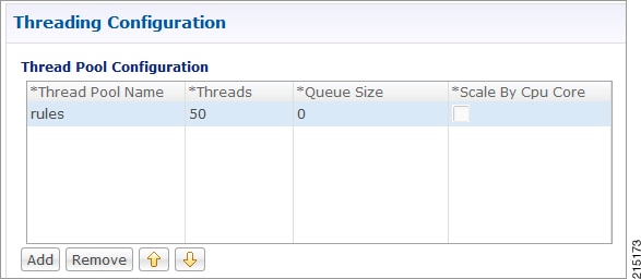
The Threading Plug-in having thread pools controls the total number of threads in CPS vDRA that are executing at any given time. Each of these thread pools have a queue associated with it.
A configuration example is shown below:
The following parameters can be configured under Threading Configuration:
|
Parameter |
Description |
|---|---|
|
Thread Pool Name |
Name of the thread pool. For more information on the thread pool names and recommended values that can be configured, refer to Threading Configuration section in the CPS vDRA Advanced Tuning Guide. |
|
Threads |
Number of threads to set in the thread pool. |
|
Queue Size |
Size of the queue before they are rejected. |
|
Scale By Cpu Core |
Select this check box to scale the maximum number of threads by the processor cores. |
Async Threading Configuration
Click Async Threading Configuration in the right pane to add the configuration in the system.
Use the default values for the Async Threading Plug-in. The Async configuration controls the number of asynchronous threads.
 Note |
Currently, CPS vDRA does not have any asynchronous threads. However, you must add “Async Threading Configuration” and keep this table empty. |
The following parameters can be configured under Async Threading Configuration.
|
Parameter |
Description |
|---|---|
|
Default Processing Threads |
The number of threads that are allocated to process actions based on priority. |
|
Default Action Priority |
The priority assigned to an action if it is not specified in the Action Configurations table. |
|
Default Action Threads |
The number of threads assigned to process the action if it is not specified in the Action Configurations table. |
|
Default Action Queue Size |
The number of actions that can be queued up for an action if it is not specified in the Action Configurations table. |
|
Default Action Drop |
DropOldestWhenFull: The oldest queued action is dropped from the queue when a new action is added to a full queue. Otherwise, the new action to add is ignored. DropWhenFull: A handler for rejected tasks that silently discards the rejected task. No execution for rejected tasks. DoNotDrop: A handler for rejected tasks that runs the rejected task directly in the calling thread of the execute method, unless the executor has been shut down, in which case the task is discarded. Default value is DropOldestWhenFull. |
|
Action Configurations Table |
|
|
Action Name |
The name of the action. This must match the implementation class name. |
|
Action Priority |
The priority of the action. Used by the default processing threads to determine which action to execute first. |
|
Action Threads |
The number of threads dedicated to processing this specific action. |
|
Action Queue Size |
The number of actions that can be queued up. |
|
Action Drop Oldest When Full |
For the specified action only: When checked, the oldest queued action is dropped from the queue when a new action is added to a full queue. Otherwise, the new action to add is ignored. |
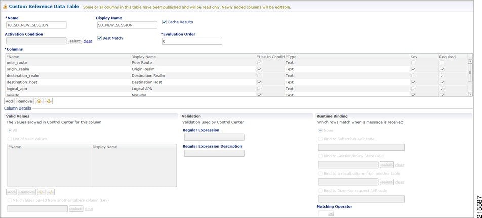
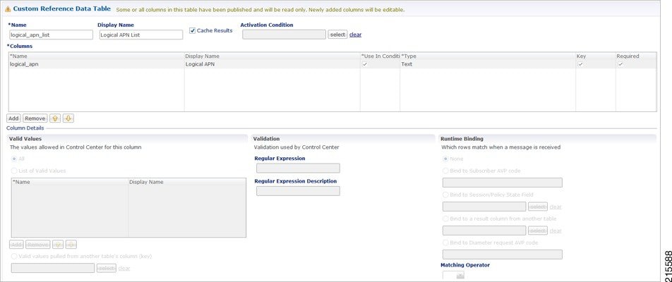
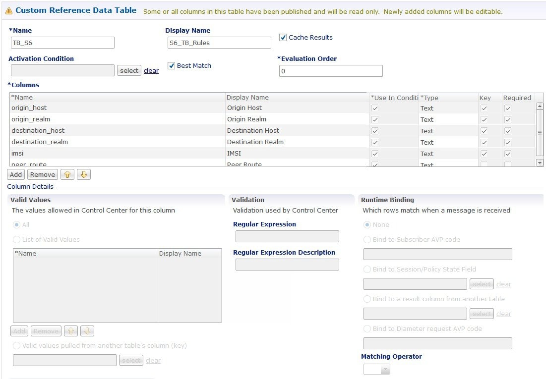
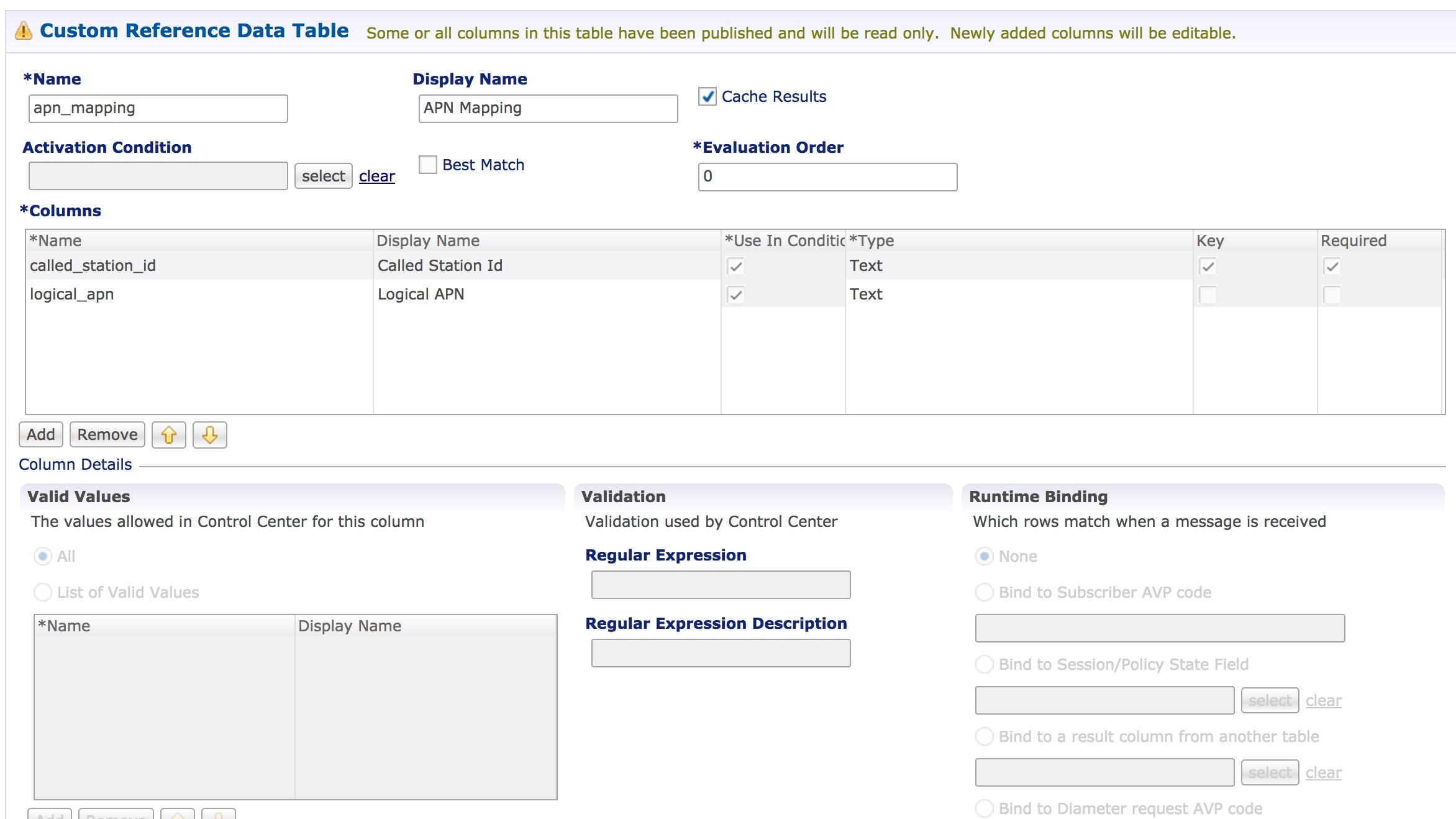
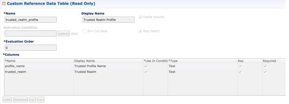
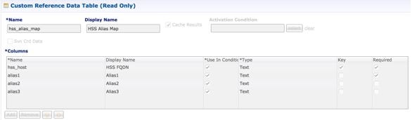
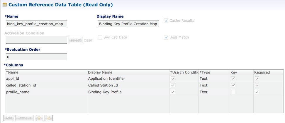
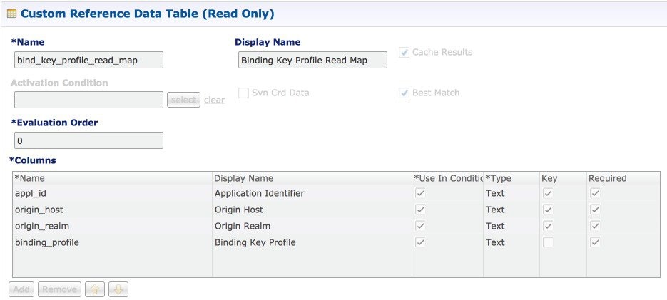
Custom Reference Data Configuration
Configure your system, cluster, and instance for the first time to use Custom Reference Data Table plug-in. Then you can create as many tables as needed.
Important |
When you add new fields in CRD, manually update the new fields with appropriate values for all the existing entries in CRD. Otherwise DRA doesn't show any values for these new fields for existing entries and this can cause routing failures. |
Click Custom Reference Data Configuration from right pane to add the configuration in the system.
-
HA example:
-
Primary Database Host/IP Address: sessionmgr01
-
Secondary Database Host/IP Address: sessionmgr02
-
Database Port: 27717
-
-
AIO example:
-
Primary Database Host/IP Address: localhost or 127.0.0.1
-
Secondary Database Host/IP Address: NA (leave blank)
-
Database Port: 27017
-
The following parameters can be configured under Custom Reference Data Configuration.
|
Parameter |
Description |
||
|---|---|---|---|
|
Primary Database Host/IP Address |
IP address or a host name of the sessionmgr database. For example, sessionmgr01. |
||
|
Secondary Database Host/IP Address |
(Optional) This field is the IP address or a host name of a secondary, backup, or failover sessionmgr database. For example, sessionmgr02. |
||
|
Database Port |
Port number of the sessionmgr.
Default value is 27717. |
||
|
Db Read Preference |
Describes how sessionmgr clients route read operations to members of a replica set. Select one of the following options from drop-down list:
Default value is Primary. For more information, see http://docs.mongodb.org/manual/core/read-preference/. |
||
|
Connection Per Host |
Number of connections that are allowed for each database host. Default value is 100. Connection Per Host is a performance tuning parameter and can be changed in case of a performance issue according to the call model and hardware. |
||
|
Avp Persists |
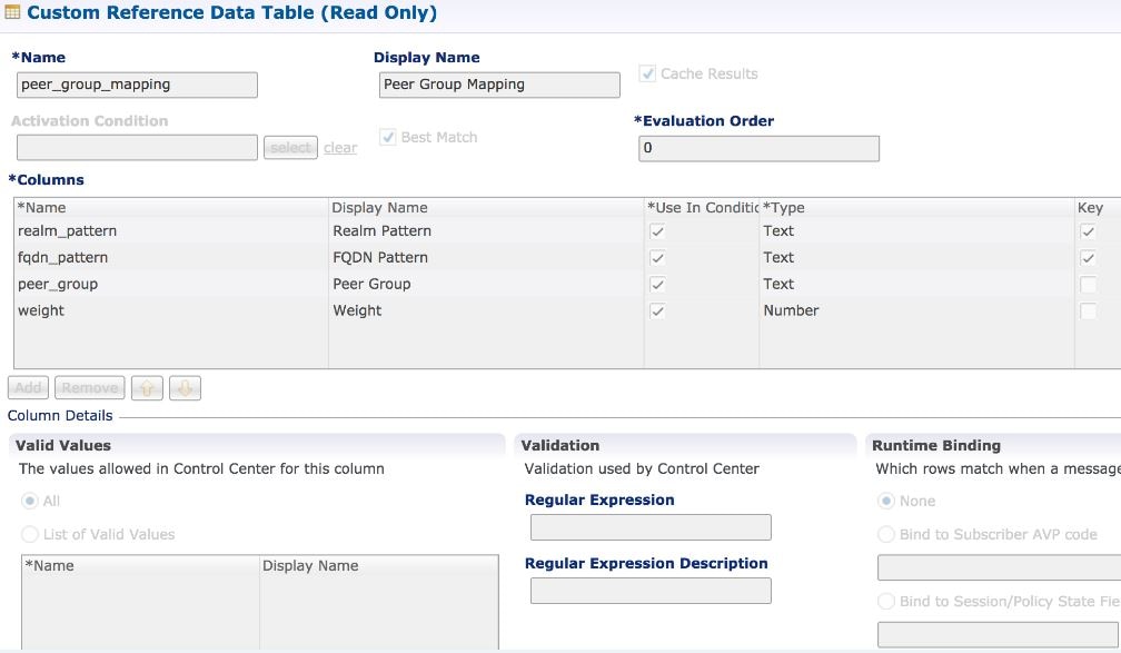
Use this table to configure certain AVPs that you want to store in the session database. AVPs that are not configured as part of this table, are not persisted.
To retrieve the stored AVPs from the session, use the Customer Reference Data Debug AVPs. This retriever is used to send the stored AVPs in any diameter message, and available in the PolicyState/Session data to Custom AVP Mapping under Custom AVP Profiles.
|
For more information on Custom Reference Data API Usage, see the CPS Operations Guide for this release.
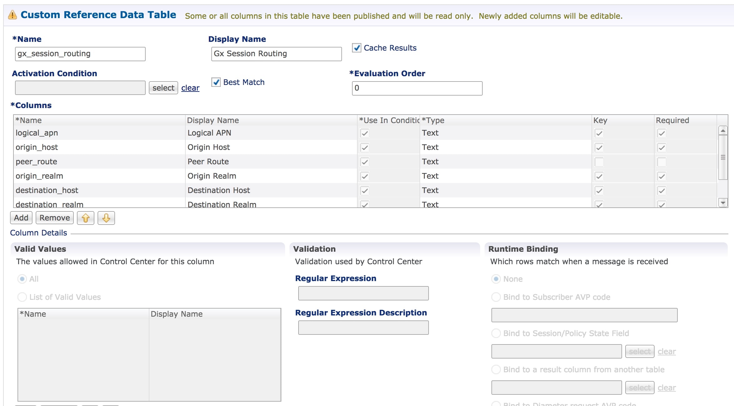
DRA Configuration
Click DRA Configuration from the right pane in Policy Builder to add the configuration in the system.
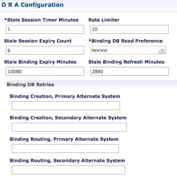
The following parameters can be configured under DRA Configuration:
|
Parameter |
Description |
||||
|---|---|---|---|---|---|
|
Stale Session Timer Minutes |
Indicates the time after which the audit RAR should be generated (in the subsequent audit RAR process cycle that runs every two minutes in CPS vDRA) for sessions that are stale. Default: 180 minutes (recommended value) Minimum: 10 minutes Maximum: 10080 minutes
|
||||
|
Rate Limiter |
Indicates the number of audit RARs per second that should be sent out by CPS vDRA. Rate Limter value is per worker value. Total number of audit RAR processed is calculated as Rate Limiter value * number of workers.
Minimum: 1 Maximum: 1000 (maximum number of RAR messages per second from vDRA to PCEF) For information on recommended value, refer to Audit Rate Limiter section in the CPS vDRA Advanced Tuning Guide. |
||||
|
Stale Session Expiry Count |
Specifies the number of retries vDRA should do for a stale session if there is no response of audit RAR or if there is Result-Code in RAA (for audit RAR) other than 5002 or 2001. Default: 6 Minimum: 0 (Session deleted without sending RAR) Maximum: 10 For information on recommended value, refer to Audit Rate Limiter section in the CPS vDRA Advanced Tuning Guide. |
||||
|
Binding DB Read Preference |
Used to select the mode when reading from Binding DB. Use "nearest" mode for better performance of traffic that needs only read operation on Binding DB. Default: Nearest For information on recommended value, refer to Audit Rate Limiter section in the CPS vDRA Advanced Tuning Guide. |
||||
|
Stale Binding Expiry Minutes |
Duration after which a binding record is validated against a session record to see if the binding should be deleted because it is stale The timer is initialized when the session is created. The records are deleted when binding expiry time is reached and no active session is found. Otherwise, the timer is updated so the binding record can be audited after another Stale Binding Expiry Minutes. Default: 10080 minutes (168 hours or one week) (recommended value) Minimum: 10 minutes Maximum: 43200 minutes (28 days) For more information about binding DB audits and stale records, see Binding DB Audit. |
||||
|
Stale Binding Refresh Minutes |
Duration for which the expiry time of the binding database records is refreshed. Default: 2880 minutes (48 hours or 2 days - recommended value). Minimum: 10 minutes Maximum: 10080 minutes (one week)
|
||||
|
Binding Creation, Primary Alternative System |
Name of vDRA system to retry Gx CCR-i When vDRA tries to route a Gx CCR-i request, but is unable to reach the database, the configured values of first the primary, then the secondary systems are used to route the Gx CCR-i to a different vDRA to try the database. The retry is stopped if that vDRA also cannot reach the database.
|
||||
|
Binding Creation, Secondary Alternative System |
Name of secondary vDRA system to retry Gx CCR-i
|
||||
|
Binding Routing, Primary Alternative System |
Name of vDRA system to retry Rx AAR When vDRA tries to route a Rx AAR request, but is unable to reach the database, the configured values of first the primary, then the secondary systems are used to route the Rx AAR to a different vDRA to try the database. The retry is stopped if that vDRA also cannot reach the database. |
||||
|
Binding Routing, Secondary Alternative System |
Name of secondary vDRA system to retry Rx AAR |
||||
|
Settings |
Refer to Settings. |
||||
|
Rate Limits |
Refer to Rate Limits. |
||||
|
DRA Feature |
Refer to DRA Feature. |
||||
|
DRA Inbound Endpoints |
Refer to DRA Inbound Endpoints. |
||||
|
DRA Outbound Endpoints |
Refer to DRA Outbound Endpoints. |
||||
|
Relay Endpoints |
Refer to Relay Endpoints. |
Settings
Click Settings check box to open the configuration pane.
The following parameters can be configured under Settings:
|
Parameter |
Description |
||
|---|---|---|---|
|
Stop Timeout Ms |
Determines how long the stack waits for all resources to stop. The delay is in milliseconds. Default: 10000 ms (recommended value) Minimum: 1000 ms Maximum: 60000 ms (one minute) |
||
|
Cea Timeout Ms |
Determines how long it takes for CER/CEA exchanges to timeout if there is no response. The delay is in milliseconds. Default: 10000 ms (recommended value) Minimum: 1000 ms Maximum: 60000 ms (one minute) |
||
|
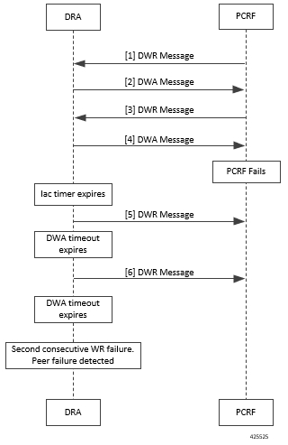
Iac Timeout Ms |
Determines how long the stack waits before initiating a DWR message exchange on a peer connection from which no Diameter messages have been received. The timeout value is in milliseconds. Default: 5000 ms (recommended value) Minimum: 1000 ms Maximum: 30000 ms (30 seconds) |
||
|
Dwa Timeout Ms |
Determines how long the stack waits for a DWA message in response to a DWR message. If no Diameter message (DWA or other message) is received on the peer connection during the first timeout period, the stack counts a failure, sends another DWR message, and restarts the Dwa timer. If no Diameter messages are received during the second timeout period, the stack counts a second failure. After two consecutive failures, the stack considers the peer connection as failed, and closes the connection. The delay is in milliseconds. Default: 10000 ms (recommended value) Minimum: 1000 ms Maximum: 60000 ms (one minute) |
||
|
Dpa Timeout Ms |
Determines how long it takes for a DPR/DPA exchange to timeout if there is no response. The delay is in milliseconds. Default: 5000 ms (recommended value) Minimum: 1000 ms Maximum: 30000 ms (30 seconds) |
||
|
Rec Timeout Ms |
Determines how long it takes for the reconnection procedure to timeout. The delay is in milliseconds. Default: 10000 ms (recommended value) Minimum: 1000 ms Maximum: 60000 ms (one minute) |
||
|
Drain Timeout Ms |
Indicates the time that a peer connection remains open for responses to be sent to peers even if DPR is sent or received by vDRA. If a DPR is sent or received by vDRA, vDRA does not route requests to the disconnecting peer connection via any routing (Dest-Host, SRK, Binding, Table-Driven). However, responses and in-flight requests sent to the corresponding peers till the duration of Drain Timeout. This allows vDRA to gracefully shut down when any remote peer sends a DPR so as to minimize the diameter message loss. Default: 2000 ms Maximum: Must be less than Dpa timeout Ms
|
||
|
Response Timeout Ms |
Response timeout in milliseconds. Default: 1700 ms |
The following figure illustrates the timers in peer detection:
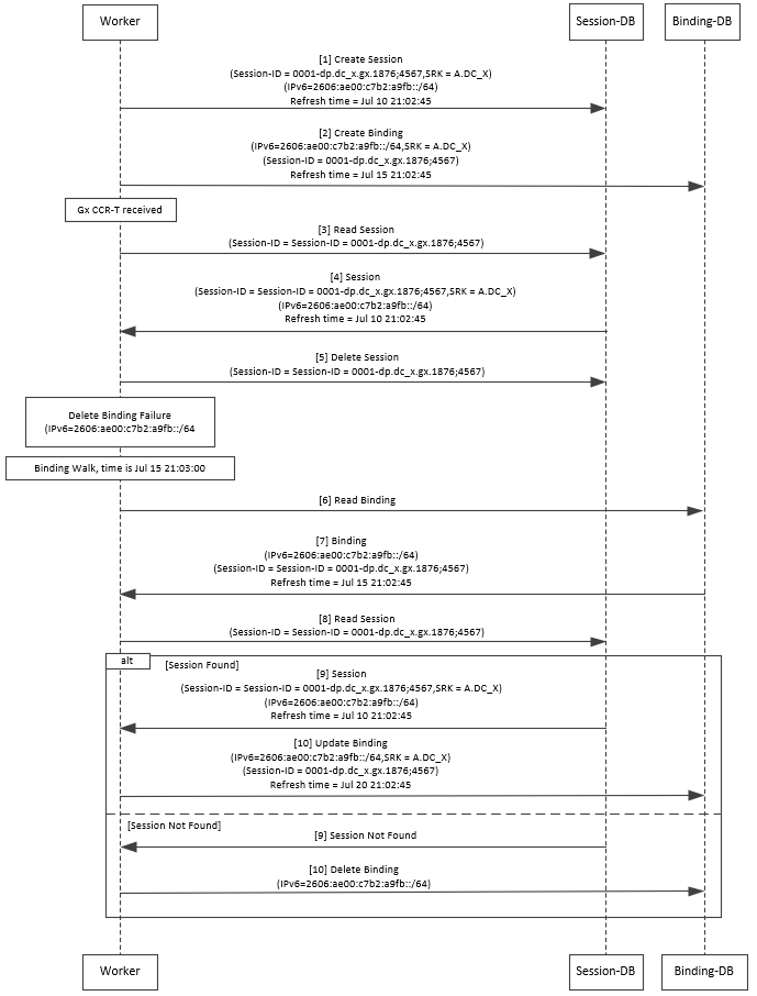
Binding DB Audit
The Binding DB Audit automatically deletes stale records from the binding DBs. When a Gx session record is created, binding records for the session binding keys are also created. When each binding record is created, the binding record expiry time is initialized to the sum of the session creation time and the Stale Binding Expiry Minutes (that you can configure in Policy Builder).
A binding record is deleted when the corresponding session record is deleted. A binding may become stale if it cannot be deleted when its associated session record is deleted (this occurs typically due to database communication failures). The binding records are audited using a binding audit background process. If the audit process finds a binding record with an expiry time in the past, the binding record is checked for staleness by checking the session database for the corresponding session record. If an active session record is found, the binding record expiry time is updated with sum of current time and the Stale Binding Expiry Minutes. If an active session is not found, the binding is considered stale and is deleted. Note that the binding audit process does not perform any Diameter signaling with the GW before deletion.
The following figures illustrate the working of binding DB:
Note |
There is a housekeeping thread to process stale sessions/bindings which does the following tasks in sequential order:
The stale session expiry task is scheduled to run every 2 minutes. This means that the stale session expiry processing is not guaranteed to happen exactly at the configured stale session expiry minutes interval. The stale session expiry processing can happen at any time within the configured stale session expiry minutes to configured stale session expiry minutes + 2 min interval. However, if the previous task execution of the above mentioned three points takes longer time to complete due to large number of stale sessions/stale bindings, the stale session expiry would run post the previous task completion which can lead to a longer delay than expected 2 minute. |
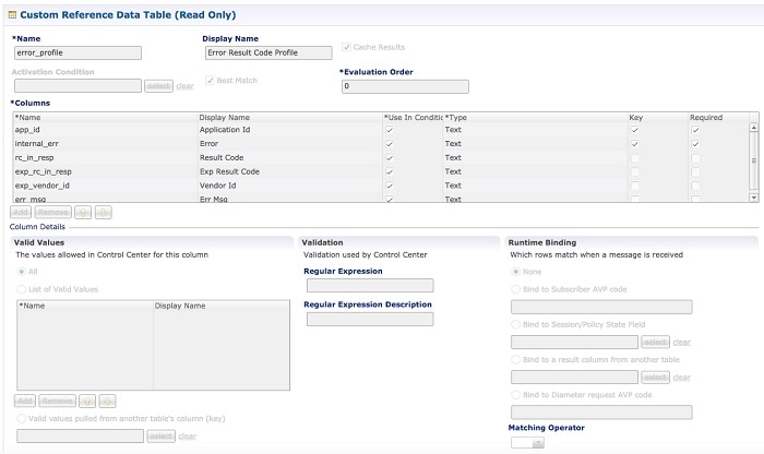
Rate Limits
Rate limit per process instance on Policy Director (lb) VM can be managed using this configuration.
Default is unchecked, that is, no rate limits for Diameter traffic (recommended setting).
If enabled, the following parameters can be configured under Rate Limits:
|
Parameter |
Description |
||
|---|---|---|---|
|
Rate Limit per Instance on Policy Director |
Allowable TPS on a single instance of policy server (QNS) process running on the Policy Director. Minimum: 1 Maximum: 5000
|
||
|
Result-Code in Response |
Indicates the error code that must be used while rejecting requests, due to rate limits being reached. Default: 3004 |
||
|
Error Message in Response |
Select the check box to drop the rate-limited messages without sending error response. If the check box is not selected, then the rate limited message are dropped with error response as configured. |
||
|
Drop Requests Without Error Response |
Select the check box to drop rate limited messages without sending error response. If the check box is unchecked, then the rate limited messages are dropped with error response as configured. To accommodate configuration to either drop the request or send an error response, a column Discard Behavior can be added under Peer Rate Limit Profile. The column may have one of the two possible values:
Default: Unchecked (recommended setting) For more information, refer to Peer Rate Limit.
|
Here is the list of the available combinations for rate limiting:
|
Rate Limiting Type |
With Error Code |
With Error Code and Error Message |
Without Error Code (Drop) |
|---|---|---|---|
|
Instance Level |
Yes |
Yes |
Yes |
|
Peer Level Egress |
Yes |
Yes |
Yes |
|
Peer Level Egress with Message Level |
Yes |
Yes |
Yes |
|
Egress Message Level (No Peer Level RL) |
Yes |
Yes |
Yes |
|
Peer Level Ingress |
Yes |
Yes |
Yes |
|
Peer Level Ingress with Message Level |
Yes |
Yes |
Yes |
|
Ingress Message Level (No Peer Level RL) |
Yes |
Yes |
Yes |
DRA Feature
Click DRA Feature check box to open the configuration pane.
The following parameters can be configured under DRA Feature:
|
Parameter |
Description |
||
|---|---|---|---|
|
Gx Session Tear Down On5065 |
By default, Gx Session Tear Down On5065 flag is enabled (recommended setting). When the PCRF responds with a Experimental Result Code of 5065 in AAAnswer on Rx Interface, DRA deletes its internal binding and session created for the transaction.A RAR with appropriate Session-Release-Cause AVP will also be sent to the PCEF.
|
||
|
Update Time Stamp On Success R A A |
When this check box is selected, session timestamp will be updated on receipt of success RAA (Result-Code: 2001) from PCEF. 1 Default is checked (recommended setting).
|
||
|
Update Time Stamp On Success C C R U |
When this check box is selected, session timestamp will be updated on receipt of success CCR-U (Result-Code: 2001) from PCEF. 2 Default is unchecked (recommended setting).
|
||
|
Enable Proxy Bit Validation |
Enables P bit validation. vDRA validates the P bit in the Diameter request and, if set, the message maybe proxied, relayed, or redirected. If this option is disabled, the P bit in the request is not checked and the request is not considered proxiable. Default: Enabled. |
||
|
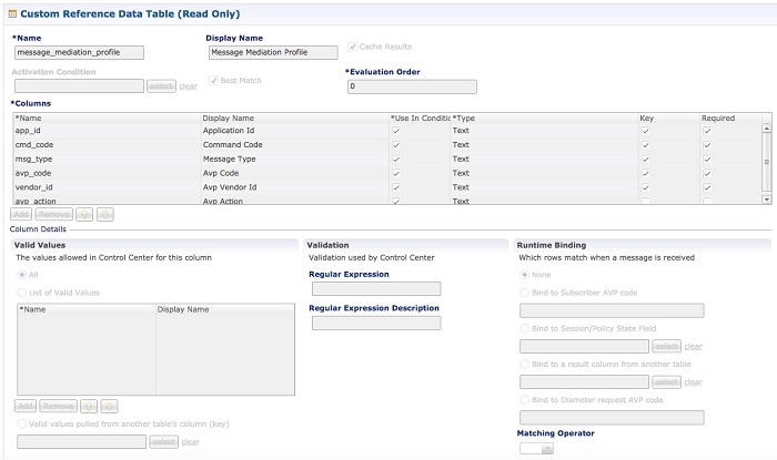
Enable Mediation |
Enable advanced mediation capabilities in both egress and ingress direction. This feature allows you to configure vDRA to change the value of the Result-Code in Diameter Answer, use mediation to hide topology, prepend label to Destination Host AVP, etc. |
||
|
Enable Doic |
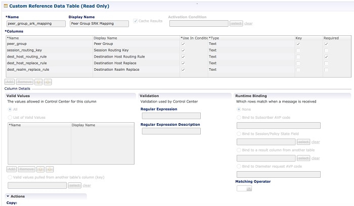
Enable or disable abatement action for Diameter requests towards PCRF, HSS, AAA, and OCS servers based on reporting of overloaded conditions using the architecture described in RFC 7683 Diameter Overload Indication Conveyance (DOIC). DOIC can be enabled/disabled at peer group level in Peer Group SRK Mapping table. If the destination peer is congested or overloaded, you can choose to either forward, divert, or drop messages. |
||
|
Enable PCRF Session Query |
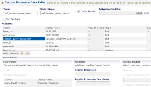
Enables or disables the PCRF session query. If you enable this, Policy DRA then supports a fallback routing for Rx AARs for VoLTE using the PCRF session query. This ensures that VoLTE calls can complete in the event that IPv6 binding is not found in the binding database. For an Rx AAR with an IPv6 binding query, vDRA provides the ability to route the Rx AAR based on an API query to the PCRF to determine if it has a session for the IPv6. The queries can be made in parallel to a configured set of query points on PCRFs. The Framed-IPv6 AVP from the Rx must be provided in the request to the PCRF. PCRF returns an SRK to be used for routing, similar to existing binding lookups. |
||
|
Create IPv6 Bindings based on PCRF Session Query |
Enables creation of IPv6 binding record in the database based on PCRF session query. When PCRF session query result (success) is received and if IPv6 record is not present in the database, vDRA creates an IPv6 binding record based on the response from the PCRF. If any CCR-I is received for the same IPv6 record, then it overwrites the IPv6 binding record. For any CCR-T, vDRA deletes the IPv6 binding record from database.
The Stale Binding Expiry and Refresh Minutes are used to clear these binding records from the database. For more information, see Binding DB Audit. |
||
|
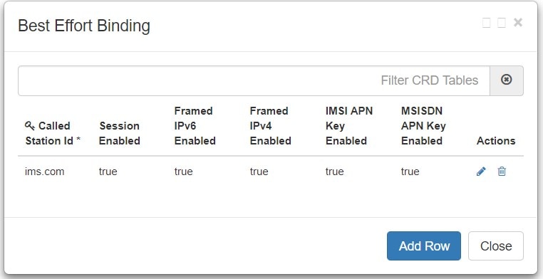
Enable Best Effort Binding |
When selected allows the operator to enable the best effort binding creation configuration on a per APN basis. The configuration is enabled on a per APN basis and controls any or all of the following bindings (for best effort):
Default is unchecked. Best effort bindings are those bindings for which DRA does not wait for DB write operations to be completed. DRA forwards the CCR without waiting for DB write and there is an asynchronous write call for best effort bindings. If there is no matching APN found in the best effort binding table from CCR-I, DRA takes the legacy behavior and treats all bindings as mandatory. The bindings to be created is primarily decided by binding creation profile and then DRA examines the best effort table to find the best effort and mandatory bindings. The session can be marked as best effort and in such cases session is not created if session Db is down but the CCR is forwarded. |
||
|
Slf Max Bulk Provisioning TPS |
Rate at which subscribers are provisioned in the SLF database. SLF bulk provisioning generates high number of database write operations in a short duration of time. To spread out the operations over a period of time and mitigate the performance issue, configure the TPS. The rate limit adds delay between transactions and thereby limits the number of transactions executed per second. For more information about SLF bulk provisioning, see the CPS vDRA Operations Guide. |
||
|
A A R Priority Processing |
In vDRA 19.4.0 and later release, this parameter has been deprecated and no longer supported. By default, when application-based client sharding is used, AAR processing is prioritized on workers. |
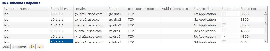
DRA Inbound Endpoints
The following parameters can be configured under DRA Inbound Endpoints:
Note |
To handle loads of 15 K TPS or more, create multiple TCP connections with PCRF and apply the same configuration to all DRA Directors. |
|
Parameter |
Description |
||||
|---|---|---|---|---|---|
|
Vm Host Name |
Host Name of the VM that hosts this CPS vDRA endpoint. |
||||
|
Ip Address |
Address on which this CPS vDRA endpoint should bind to. |
||||
|
Realm |
Realm of the CPS vDRA endpoint. |
||||
|
Fqdn |
Fully Qualified Domain Name of the CPS vDRA end point. |
||||
|
Transport Protocol |
Allows you to select either 'TLS', TCP' or 'SCTP' for the selected DRA endpoint. Default value is TCP. If the DRA/relay endpoint is to be configured for SCTP, the Transport Protocol should be selected as SCTP for those endpoints. TLS: Enables the connection as TLS from inbound . The supported TLS version is 1.2 and only for Rx application it is supported. |
||||
|
Multi-Homed IPs |
This is a comma separated list of IP addresses that CPS vDRA will use to start the diameter stack with multi-homing enabled for SCTP transport. Diameter stack with TCP transport will still use the existing 'Local Bind Ip' field to specify any specific IP address for TCP stack. CPS vDRA will use the 'Local Bind Ip' to bring up SCTP stack and use it along with the ‘Multi Homing Hosts' to start the SCTP transport with multi-homing support.
The configuration for multi-homing is validated by netstat command on lb01:
|
||||
|
Application |
Refers to 3GPP Application ID of the interface. You can select multiple applications on a peer connection. For example, S6a and SLg on a single IPv4/SCTP Multi-homed peer connection. |
||||
|
Enabled |
Check to enable the endpoint. |
||||
|
Base Port |
Refers to the port on which the CPS vDRA listens for incoming connections. |
An example configuration is shown below:
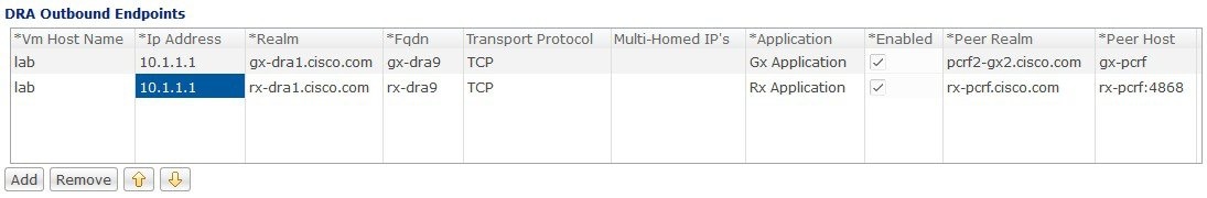
DRA Outbound Endpoints
The following parameters can be configured under DRA Outbound Endpoints:
|
Parameter |
Description |
||||
|---|---|---|---|---|---|
|
Vm Host Name |
Host Name of the VM that hosts this CPS vDRA endpoint. |
||||
|
Ip Address |
Address on which this CPS vDRA endpoint should bind to. |
||||
|
Realm |
Realm of the CPS vDRA endpoint. |
||||
|
Fqdn |
Fully Qualified Domain Name of the CPS vDRA end point. |
||||
|
Transport Protocol |
Allows you to select either 'TCP' or 'SCTP' for the selected CPS vDRA endpoint. Default value is TCP. If the DRA/relay endpoint is to be configured for SCTP, the Transport Protocol should be selected as SCTP for those endpoints. |
||||
|
Multi-Homed IPs |
This is a comma separated list of IP addresses that CPS vDRA will use to start the diameter stack with multi-homing enabled for SCTP transport. Diameter stack with TCP transport will still use the existing 'Local Bind Ip' field to specify any specific IP address for TCP stack. CPS vDRA will use the 'Local Bind Ip' to bring up SCTP stack and use it along with the ‘Multi Homing Hosts' to start the SCTP transport with multi-homing support.
The configuration for multi-homing is validated by netstat command on lb01:
|
||||
|
Application |
Refers to 3GPP Application ID of the interface. |
||||
|
Enabled |
Check to enable the endpoint. |
||||
|
Peer Realm |
Diameter server realm. |
||||
|
Peer Host |
Diameter server host. By default, the connection is initiated on the standard diameter port (3868). If a different port needs to be used than the peer name must be defined using the host:port format. |
An example configuration is shown below:
Enable TLS and MTLS for Diameter Encryption
RFC 6733 Protocol Model
According to the RFC 6733 protocol model, you can configure the security details to initialize the TLS or MTLS connection.
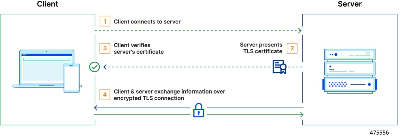
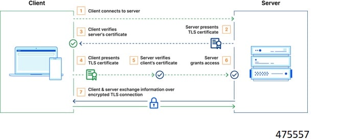
The sequence for the data transmission is as follows:
-
Establishes TCP Connection
-
Establishes TLS or MTLS connection over TCP.
-
Exchanges CER/CEA message between the peers over TLS or MTLS.
-
Exchanges application data over TLS or MTLS.
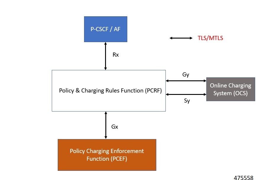
Feature Description
The vDRA supports a Transport Layer Security (TLS) and MTLS (Mutual Transport Layer Security) secure channels for diameter peer connection. The following architecture describes TLS and MTLS in DRA.
Enabling TLS Protocol in the Policy Builder
Use the Policy Builder to enable the TLS protocol.
-
Log in to the Policy builder.
-
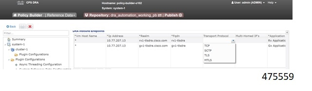
In the DRA Inbound Endpoint, from the Transport Protocol drop-down list, choose TLS to enable a connection as TLS from inbound. The supported version of TLS is 1.2 and it supports the Gx, Rx, Gy and Sy application.
You can publish the configuration after providing necessary stack details.
Enabling MTLS in Policy Builder
The MTLS is configurable in the Policy Builder GUI.
-
Log in to the Policy builder.
-
In the DRA Inbound Endpoint, from the Transport Protocol drop-down list, choose MTLS to enable a connection as MTLS from inbound. The supported version of MTLS is 1.2 and it supports the Gx, Rx, Gy and Sy application.
An example configuration is shown below:
Importing Certificate through CLI
Prerequistes: Ensure that a cps.pem file is present in /data/keystore in the orchestrator container before executing the CLI.
Follow the steps to import certificates through CLI:
-
Copy the certificates files to the master VM under /data/orchestrator/pemKey to import the tls certificate.
-
Load the certificates to the Diameter application using the following CLI command dra-tls cert import certificate file private file-
Input certificate and private files for the CLI command.
-
Enter the keystore password to encrypt the certificate file. Backend script converts files into JKS with encryption and copies to the diameter-endpoint containers.
Note
-
Ensure to enter a Password with minimum of six characters, Alphanumeric, and special characters.
-
Renegotiation of TLS Handshake for an established connection with the new certificate from the server side [Diameter] without any call failures are not supported.
-
-
Example 1:
dra-tls cert import certificate.pem private.pem
admin@orchestrator[pn-master-0]# dra-tls cert import tls-cert.pem private.pem
enter the Keystore Password for this private.pem cert:********
Importing keystore /data/pemKey/certificate-tls.p12 to /data/pemKey/diameter-endpoint-tls.jks...
Example 2
admin@orchestrator[pn-master-0]# dra-tls cert import CA-cert.pem CA-key.pem
enter the Keystore Password for this private.pem cert:********
Importing keystore /data/pemKey/certificate-tls.p12 to /data/pemKey/diameter-endpoint-tls.jks...
Warning:
The JKS keystore uses a proprietary format. It is recommended to migrate to PKCS12 which is an industry standard format using "keytool -importkeystore -srckeystore /data/pemKey/diameter-endpoint-tls.jks -destkeystore /data/pemKey/diameter-endpoint-tls.jks -deststoretype pkcs12".
Import Successfully Completed for 192.1.XX.XX.
Importing Certificate to 192.1.XX.XX.
Import Successfully Completed for 192.1.XX.XX.
Importing Certificate to 192.1.XX.XX.
Import Successfully Completed for 192.1.XX.XX.
Importing Certificate to mongo-admin-a:27017 Database.
Certificate Imported Successfully.
Note |
|
Creating TLS Certificate Before Expiration and Raising Alerts
vDRA supports the following function:
-
Installation of a new certificate on the Directors before expiration of a TLS certificate
Note
After installation, the same certificate must be installed on the client.
-
After replacing a new certificate, the client initiates reestablishment of connections within the maintenance window to avoid call failures.
-
Monitoring the certificate validity will be every one hour, from the time of application restart.
-
Alert notification prior to the certificate expiration date based on the following alert notification metrics.
Table 11. Alert Notification Expiration in Days
Alert Level
60 days
Minor
40 days
Major
14 days
Critical
For more information, see the Application Notifications table and Alert Rules section in the CPS vDRA SNMP and Alarms Guide.
Inservice Certificate Management
Ensure to follow the procedure to install a new TLS certificate on the Director before the TLS certificate expiration:
-
Place the new certificate in the following path /data/orchestrator/pemKey/.
-
After placing a new updated certificate on the Master VM, use the same CLI command to replace the existing certificate.
The existing connection from the older certificate remains connected and there should not be any call failure.
-
To get the new certificate in place, terminate the existing connection and the new connection must be negotiated by the client.
Relay Endpoints
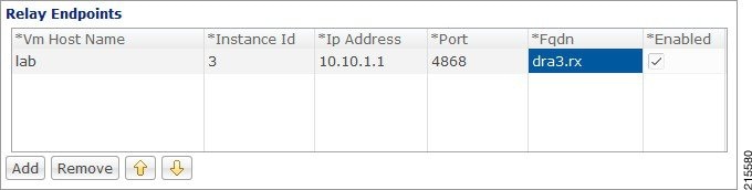
The following parameters can be configured under Relay Endpoints:
|
Parameter |
Description |
||
|---|---|---|---|
|
Vm Host Name |
Host Name of the VM that hosts this Relay endpoint. |
||
|
Instance Id |
Instance Identifier is the ID of the current Instance. |
||
|
Ip Address |
Address on which this DRA endpoint should bind to.
|
||
|
Port |
Port is the listening port for this instance. |
||
|
Fqdn |
Fully Qualified Domain Name of the DRA end point. |
||
|
Enabled |
Check to enable endpoint. |
An example configuration is shown below:
Policy Routing for Real IPs with Relay Endpoints
vDRA relay links consist of a control plane and a data plane.
The control plane uses virtual IPs and the data plane uses real IPs.
If the control and data plane use the same links, and those links are configured with VIPs, by default, the data plane uses the VIP as its source address for outgoing connections. The data plane uses the VIP as the source address only if the VIP is active on the data plane's outgoing interface.
To avoid this situation, policy routing is used to force the data plane to use the real IP address of the outgoing interface instead of the VIP.
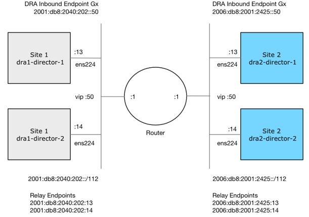
Example of a vDRA Relay Endpoints
In the following example network, only the DRA director VMs and their relay links are displayed. In a real scenario, many more links may exist on the DRA director VMs.
Policy Routing
Linux policy routing includes rules and routing tables. The rules identify traffic and point to a user-defined routing table. The routing table contains customized routes.
To prevent the Relay Link's data plane from using the VIP as a source address, a rule is created to identify the real IP in the destination address and identify the desired routing table.
Configure Policy Routing
The following configuration procedure is performed on Site 1 dra1-director-1. Repeat the procedure for all other dra-directors and modify the IP addresses accordingly.
Perform the following steps on each dra-director VM to configure policy routing:
-
Create a custom routing table
-
Create an IP rule for each remote relay endpoint's real IP address
-
Add a route to the custom routing table that specifies the real IP source address
Set up Custom Routing Table
Set up the custom routing table as shown in the following example:
echo "200 dra.relay" | sudo tee --append /etc/iproute2/rt_tables
Define IP Rules
The following rules match the packets destined to the real IPs of interface ens224 on dra2-director1 and dra2-director2:
ip -6 rule add to 2006:db8:2001:2425::13 table dra.relay
ip -6 rule add to 2006:db8:2001:2425::14 table dra.relay
Define the Route
The following example of the route uses the router's interface as the next hop and specifies ens224's real IP address as the source address for outgoing packets.
ip route add 2006:db8:2001:2425::/112 via
2001:db8:2040:202::1 src 2001:db8:2040:202::13 table dra.relay
Validate the Routing
Use the following example commands to validate the route selection for remote relay real IP and VIP addresses.
ip -6 route show table dra.relay
ip -6 route get 2006:db8:2001:2425::13
ip -6 route get 2006:db8:2001:2425::14
ip -6 route get 2006:db8:2001:2425::50
Persistent Configuration
In order for the Policy Routing configuration to survive a reboot, add the configuration commands to /etc/network/interfaces under interface ens224 as shown below:
auto ens224
iface ens224 inet static
address 192.169.22.13
netmask 255.255.255.0
iface ens224 inet6 static
address 2001:db8:2040:202::13
netmask 112
up ip route add 2006:db8:2001:2425::/112 via 2001:db8:2040:202::1
up ip -6 rule add to 2006:db8:2001:2425::13 table dra.relay
up ip -6 rule add to 2006:db8:2001:2425::14 table dra.relay
up ip route add 2006:db8:2001:2425::/112 via 2001:db8:2040:202::1 src 2001:
db8:2040:202::13 table dra.relay
down ip route del 2006:db8:2001:2425::/112 via 2001:db8:2040:202::1
down ip -6 rule del to 2006:db8:2001:2425::13 table dra.relay
down ip -6 rule del to 2006:db8:2001:2425::14 table dra.relay
down ip route del 2006:db8:2001:2425::/112 via 2001:db8:2040:202::1 src
2001:db8:2040:202::13 table dra.relay
Configure Policy Routing with Deployer/Installer
Configure the VM artifacts and the cloud config to set up policy routing using the deployer.
VM Artifacts
Add Policy Route configuration to the DRA director VM's interfaces.esxi file as shown in the following example:
cps@installer:/data/deployer/envs/dra-vnf/vms/dra-director
/dra-director-1$ cat interfaces.esxi
auto lo
iface lo inet loopback

auto ens160
iface ens160 inet static
address 10.81.70.191
netmask 255.255.255.0
gateway 10.81.70.1

auto ens192
iface ens192 inet static
address 192.169.21.13
netmask 255.255.255.0

auto ens224
iface ens224 inet static
address 192.169.22.13
netmask 255.255.255.0
iface ens224 inet6 static
address 2001:db8:2040:202::13
netmask 112
up ip route add 2006:db8:2001:2425::/112 via 2001:db8:2040:202::1
up ip -6 rule add to 2006:db8:2001:2425::13 table dra.relay
up ip -6 rule add to 2006:db8:2001:2425::14 table dra.relay
up ip route add 2006:db8:2001:2425::/112 via 2001:db8:2040:202::1 src
2001:db8:2040:202::13 table dra.relay
down ip route del 2006:db8:2001:2425::/112 via 2001:db8:2040:202::1
down ip -6 rule del to 2006:db8:2001:2425::13 table dra.relay
down ip -6 rule del to 2006:db8:2001:2425::14 table dra.relay
down ip route del 2006:db8:2001:2425::/112 via 2001:db8:2040:202::1 src
2001:db8:2040:202::13 table dra.relay

auto ens256
iface ens256 inet static
address 192.169.23.13
netmask 255.255.255.0
cps@installer:/data/deployer/envs/dra-vnf/vms/dra-director/dra-director-1$
Cloud Config
Create the dra.relay routing table on the dra-directors by adding the following bootcmd: to user_data.yml and storing the file at /data/deployer/envs/dra-vnf/vms/dra-director/user_data.yml. The sed command prevents adding a routing table every time the VM boots.
bootcmd:
 - "sed -i -e '/^200 *dra.relay/d' /etc/iproute2/rt_tables"
 - "sh -c \"echo '200     dra.relay' >> /etc/iproute2/rt_tables\""
Example of user_data.yml:
#cloud-config
debug: True
output: {all: '| tee -a /var/log/cloud-init-output.log'}
users:
- name: cps
sudo: ['ALL=(ALL) NOPASSWD:ALL']
groups: docker
ssh-authorized-keys:
- ssh-rsa AAAAB3NzaC1yc2EAAAADAQABAAABAQDzjJjndIvUiBta4VSIbd2gJmlMWcQ8wtejgAbi
XtoFZdtMdo9G0ZDEOtxHNNDPwWujMiYAkZhZWX/zON9raavU8lgD9+YcRopWUtujIC71YjtoxIjWIBBbrtqt
PlUXMUXQsi91RQbUtslENP+tSatS3awoQupyBMMSutyBady/7Wq0UTwFsnYs5Jfs8jIQuMfVQ9uJ4mNn7wJ0
N+Iaf27rE0t3oiY5DRN6j07WhauM6lCnZ1JDlzqmTnTHQkgJ3uKmQa5x73tJ1OW89Whf+R+dfslVn/yUwK/
vf4extHTn32Dtsxkjz7kQeEDgCe/y7owimaEFcCIfEWEaj/50jegN cps@root-public-key
resize_rootfs: true
write_files:
- path: /root/swarm.json
content: |
{
"role": "{{ ROLE }}",
"identifier": "{{ IDENTIFIER }}",
"master": "{{ MASTER_IP }}",
"network": "{{ INTERNAL_NETWORK }}",
{% if WEAVE_PASSWORD is defined %}"weavePw": "{{ WEAVE_PASSWORD }}",
{% endif %}
"zing": "{{ RUN_ZING | default(1) }}",
"cluster_id": "{{ CLUSTER_ID }}",
"system_id": "{{ SYSTEM_ID }}"
}
owner: root:root
permissions: '0644'
- path: /home/cps/.bash_aliases
encoding: text/plain
content: |
# A convenient shortcut to get to the Orchestrator CLI
alias cli="ssh -p 2024 admin@localhost"
alias pem="wget --quiet http://171.70.34.121/microservices/latest/cps.pem ;
chmod 400
cps.pem ; echo 'Retrieved \"cps.pem\" key file'"
owner: cps:cps
permissions: '0644'
- path: /etc/pam.d/common-password
content: |
#
# /etc/pam.d/common-password - password-related modules common to all services
#
# This file is included from other service-specific PAM config files,
# and should contain a list of modules that define the services to be
# used to change user passwords. The default is pam_unix.
# Explanation of pam_unix options:
#
# The "sha512" option enables salted SHA512 passwords. Without this option,
# the default is Unix crypt. Prior releases used the option "md5".
#
# The "obscure" option replaces the old `OBSCURE_CHECKS_ENAB' option in
# login.defs.
#
# See the pam_unix manpage for other options.
# As of pam 1.0.1-6, this file is managed by pam-auth-update by default.
# To take advantage of this, it is recommended that you configure any
# local modules either before or after the default block, and use
# pam-auth-update to manage selection of other modules. See
# pam-auth-update(8) for details.
# here are the per-package modules (the "Primary" block)
password requisite pam_pwquality.so retry=3 minlen=8
minclass=2
password [success=2 default=ignore] pam_unix.so obscure use_authtok
try_first_pass sha512 remember=5
password sufficient pam_sss.so use_authtok
# here's the fallback if no module succeeds
password requisite pam_deny.so
# prime the stack with a positive return value if there isn't one already;
# this avoids us returning an error just because nothing sets a success code
# since the modules above will each just jump around
password required pam_permit.so
# and here are more per-package modules (the "Additional" block)
# end of pam-auth-update config
owner: root:root
permissions: '0644'
runcmd:
- [vmware-toolbox-cmd, timesync, enable ]
bootcmd:
- "sed -i -e '/^200 *dra.relay/d' /etc/iproute2/rt_tables"
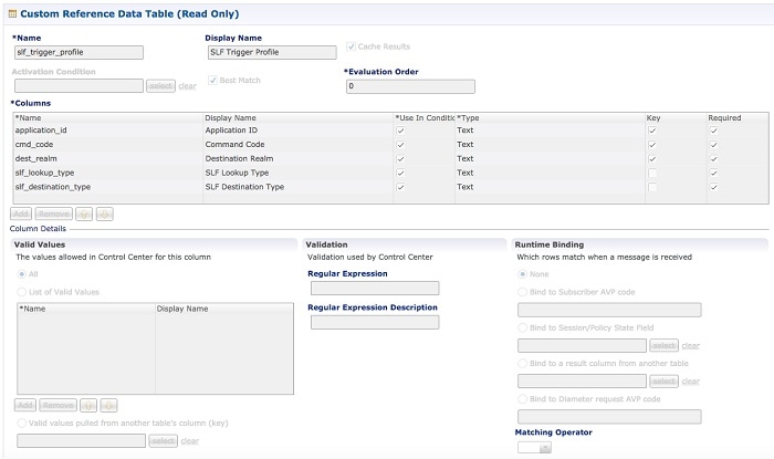
- "sh -c \"echo '200 dra.relay' >> /etc/iproute2/rt_tables\""SLF Configuration
You can specify whether the IMSI and MSISDN values are validated in SLF API.
By default, SLF validation is disabled.
To set up SLF validation, create SLF Configuration from the Plugin Configuration in Policy Builder.
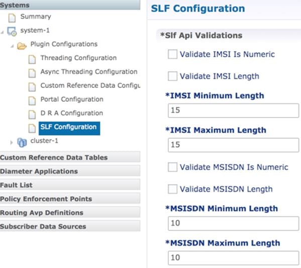
The following table describes the SLF API validations that you can configure:
|
Field |
Description |
|---|---|
|
Validate IMSI is Numeric |
If checked: IMSI received in the SLF API request must be numeric If unchecked: IMSI numeric validation is not performed on the IMSI received in the SLF API request |
|
Validate IMSI Length |
If checked: IMSI length is validated based on the specified IMSI Minimum Length (inclusive) and IMSI Maximum Length (inclusive) If unchecked: IMSI length validation is not performed on the IMSI received in the SLF API request |
|
Validate MSISDN is Numeric |
If checked: MSISDN received in the SLF API request must be numeric If unchecked: MSISDN numeric validation is not performed on the MSISDN received in the SLF API request |
|
Validate MSISDN Length |
If checked: MSISDN length is validated based on the specified MSISDN Minimum Length (inclusive) and MSISDN Maximum Length (inclusive) If unchecked: MSISDN length validation is not performed on the MSISDN received in the SLF API request |
Ingress and Egress API Rate limit Configuration
Feature Description
The vDRA uses PCRF session query to query SRK from PCRF to route the request and then recreates the binding entry. There is no rate limit for a PCRF session query triggered from vDRA. Similarly, Ingress APIs (Binding/Session/SLF/CRD/SVN/Topology/Grafana/Promethus) does not have an overload protection mechanism.
In the CPS 22.1.0 and later releases, vDRA supports a configurable option to rate-limit the incoming traffic and outgoing traffic on the API interface at director level. This rate limiting process protects the system when acting as a client or server. Also, to prevent any back pressure and working on stale messages, vDRA supports configurable queue size and length message SLAs.
Egress API Rate Limiting
vDRA supports PCRF Session Query API rate limits at director level because applying rate limit at worker level can cause uneven distribution of rate limit across Workers.
For example, possibilities of same workers receiving all Rx AAR messages that need PCRF session query, and vDRA can apply rate limit only for that worker. This causes Rx AAR to for that worker even though remaining workers are under rate limit. To avoid this issue, vDRA supports rate limit configurations at the director level.
Note |
By default, rate limit is not configured for egress API. |
The functions of egress rate limiting are:
-
The Director triggers PCRF session query based on the configured rate limit. For example, ff configured rate limit is 50, then director allows only first 50 Rx AAR requests per second to trigger PCRF session query and remaining requests are dropped. vDRA sends Rx AAA for dropped PCRF Session query with error message as “PCRF Session Query Throttled”. vDRA maintains internal error code as “027”.
-
If PCRF session query gets triggered due to “No Binding Found” error and PCRF session query got rate limited, then vDRA returns an error message: “4006:027 – PCRF Session Query Throttled”
-
If PCRF session query gets triggered due to “Binding DB Error” error and PCRF session query got rate limited, then vDRA returns error message:
“4007:027 – PCRF Session Query Throttled”
Ingress API Rate limiting
Following are the categories of Ingress APIs for which you can set rate limits:
-
Binding API
-
SLF API
-
Topology API (Peer/Relay connections)
-
OAM API(CRD/PB/CustRefData/Grafana/Promethues/SVN)
The functions of ingress Rate Limiting are:
-
Ingress API is rate limited in HAProxy service.
-
In vDRA, haproxy-common running in master/control-0/control-1/directors is used for load balancing of Policy Builder, Grafana, UI, CC, a so on. The haproxy-common receives request from client and forwards the request to vDRA backend servers.
-
Ingress requests reaching haproxy-common is tracked in stick-table with server destination IP as key.
-
In frontend, stick-table entries get compared with configured rate limit for respective ingress API. If the stick-table entries are greater than configured rate limit, then HAProxy sends HTTP deny status to the client. Otherwise, vDRA processes the request and send success status to client.
-
vDRA returns error code 429 as deny status to the client for all the failed requests due to rate limit.
-
Set the rate limit. For example:
-
If you want to set rate limit as 100 and the clients are configured to send requests only to haproxy-common running in master, then set rate limit as 100.
-
If the clients are configured to send requests to haproxy-common running master/control-0, then rate limit should be set as 50. So that two HAProxy running in master/control-0 provides 100 TPS.
-
In DRA, to make sure that DRA reaches the configured rate limit, additional 25 per cent is added to configured rate limit. This is mainly to get approximate rate limit in DRA. For example, If a rate limit is set as 500, then DRA internally adds extra 25 per cent to the configured rate limit 500 and the rate limit is set at 625. Thus, DRA allows requests 500–625.
-
Sample HAProxy configuration to rate limit ingress API:
frontend https_all_servers
	      description Unified API,CC,PB,Grafana,CRD-API,PB-API,Promethues
	      bind :443

      #ACL for Unified Binding IMSI-APN API
      acl binding_api_imsi_apn path_beg  /dra/api/bindings/imsiApn /dra/api/deleteBinding/imsiApn
      http-request deny deny_status 429 if binding_api_imsi_apn { dst,table_http_req_rate(binding_api_imsi_apn_servers) gt 625 }
      use_backend binding_api_imsi_apn_servers if binding_api_imsi_apn

       backend binding_api_imsi_apn_servers
       mode http
       balance source
       option httpclose
       option abortonclose
       stick-table type ip size 1m expire 1s store http_req_rate(1s)
       http-request track-sc1 dst table binding_api_imsi_apn_servers
       server haproxy-api-s101 haproxy-api-s101:80 check inter 10s resolvers dns resolve-prefer ipv4

       acl authoriseReadonlyUsers http_auth_group(cps_user_list) qns-ro
       acl authoriseAdminUsers http_auth_group(cps_user_list) qns
       http-request auth realm CiscoApiAuth if !authoriseReadonlyUsers !authoriseAdminUsers
       http-request deny if !METH_GET authoriseReadonlyUsers
Configuring Egress API Rate Limit in the Policy Builder
You can configure egress API rate limit for PCRF Session Query per director in the DRA Configuration.
-
In the Policy Builder, click DRA Configuration from the left pane to add the configuration in the system.
Figure 15. Director PCRF Session Query Limits 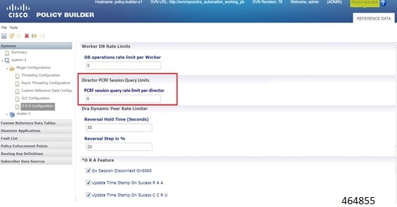
-
Configure the following parameters under DRA Configuration:
Table 14. DRA Configuration Parameters Parameter
Description
DB operations rate limit per Worker
Specifies that the rate limit is per worker for DB operations.
Default: By default, the rate limit is in disabled state.
PCRF session query rate limit per director
Specifies that the rate limit is for PCRF session query at Director level. Make sure to select the Director PCRF Session Query Limits” in the Policy Builder to view “PCRF session query limits per director” field.
Default: By default the rate limit is in disabled state.
Reversal Hold Time (Seconds)
Specifies the reversal hold time in seconds.
Reversal Step in %
Specifies the reverstal step in percentage.
Gx Session Disconnect on5065
By default, Gx Session Disconnect On5065 flag is enabled (recommended setting).
When the PCRF responds with a Experimental Result Code of 5065 in AAAnswer on Rx Interface, DRA deletes its internal binding and session created for the transaction.A RAR with appropriate Session-Release-Cause AVP will also be sent to the PCEF.
Important
When using this flag, there is always a database query to fetch Gx session id. This results in linear increase in database transactions with AAR traffic on Rx interface. Update Time Stamp On Success R A A
When this check box is selected, session timestamp will be updated on receipt of success RAA (Result-Code: 2001) from PCEF. 3
Default is checked (recommended setting).
Important
When using this flag, there is always a database query to fetch Gx session id. This results in linear increase in database transactions with AAR traffic on Rx interface. Update Time Stamp On Success C C R U
When this check box is selected, session timestamp will be updated on receipt of success CCR-U (Result-Code: 2001) from PCEF. 4
Default is unchecked (recommended setting).
Important
When using this flag, there is always a database query to fetch Gx session id. This results in linear increase in database transactions with AAR traffic on Rx interface. 3 The time stamp is updated on generation of Stale RAR. Also, if a success RAR/RAA(2001) comes after generation of Stale RAR, then the Stale RAR counter is reset. 4 The time stamp is updated on generation of Stale RAR. Also, if a success CCR(U)/CAA(2001) comes after generation of Stale RAR, then the Stale RAR counter is reset.
Configuring Ingress API Rate Limit
You can configure Ingress API rate limits to set the environment variables and use them for checking ingress or egress API rate limit in the haproxy.cfg.tmpl file. The CLI updates are applied only in haproxy-common containers because haproxy-common is used for load balancing of Policy Builder, Grafana, UI, API, CC, and so on.
After CLI updates the rate limit in haproxy config file in haproxy-common containers, haproxy is restarted automatically to apply new rate limits.
Note |
Since these CLIs internally applies the rate limit and restart haproxy, you need not manually restart haproxy-common in Master/Control/diameter containers after configuring new rate limits. |
You can set common rate limit for all binding API using the CLI dra set-ratelimit binding-api rate limit value . vDRA provides options to override common rate limits for imsi, imsi-apn, msisdn, msisdn-apn, and ipv6 binding api by specifying binding type in CLI as follows:
dra set-ratelimit binding-api-imsi | binding-api-imsi-apn | binding-api-msisdn
| binding-api-msisdn-apn | binding-api-ipv6]value
By default, DRA does not apply any rate limit for ingress APIs.
Use the following CLI commnads to select different ingress API types to set, remove or show rate limits.
-
dra set-ratelimit binding-api <rate limit value>
-
dra set-ratelimit binding-api-imsi <rate limit value>
-
dra set-ratelimit binding-api-imsi-apn <rate limit value>
-
dra set-ratelimit binding-api-msisdn <rate limit value>
-
dra set-ratelimit binding-api-msisdn-apn <rate limit value>
-
dra set-ratelimit binding-api-ipv6 <rate limit value>
-
dra set-ratelimit session-api <rate limit value>
-
dra set-ratelimit slf-api <rate limit value>
-
dra set-ratelimit topology-api <rate limit value>
-
dra set-ratelimit oam-api <rate limit value>
-
dra remove-ratelimit binding-api
-
dra remove-ratelimit binding-api-imsi
-
dra remove-ratelimit binding-api-imsi-apn
-
dra remove-ratelimit binding-api-msisdn
-
dra remove-ratelimit binding-api-msisdn-apn
-
dra remove-ratelimit binding-api-ipv6
-
dra remove-ratelimit session-api
-
dra remove-ratelimit slf-api
-
dra remove-ratelimit topology-api
-
dra remove-ratelimit oam-api
-
dra show-ratelimit
-
dra show-ratelimit binding-api
-
dra show-ratelimit binding-api-imsi
-
dra show-ratelimit binding-api-imsi-apn
-
dra show-ratelimit binding-api-msisdn
-
dra show-ratelimit binding-api-msisdn-apn
-
dra show-ratelimit binding-api-ipv6
-
dra show-ratelimit slf-api
-
dra show-ratelimit session-api
-
dra show-ratelimit topology-api
-
dra show-ratelimit oam-api
For more information, see the CLI Commands section in the CPS vDRA Operations Guide.


 Feedback