The documentation set for this product strives to use bias-free language. For the purposes of this documentation set, bias-free is defined as language that does not imply discrimination based on age, disability, gender, racial identity, ethnic identity, sexual orientation, socioeconomic status, and intersectionality. Exceptions may be present in the documentation due to language that is hardcoded in the user interfaces of the product software, language used based on RFP documentation, or language that is used by a referenced third-party product. Learn more about how Cisco is using Inclusive Language.
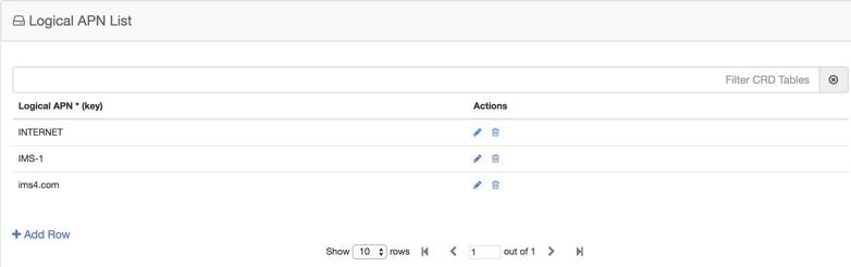
The logical APN
feature allows multiple users to access different physical target networks
through a shared APN access point. The logical APN feature reduces the amount
of APN provisioning required by consolidating access all real APNs through a
single virtual APN. Therefore, only the virtual APN needs to be provisioned at
Control Centre, instead of each of the real APNs to be reached.
For details on Peer Group, refer to Peer Group Mapping and Peer Group SRK Mapping.
An example
configuration is shown below:
Figure 1. Logical APN
List
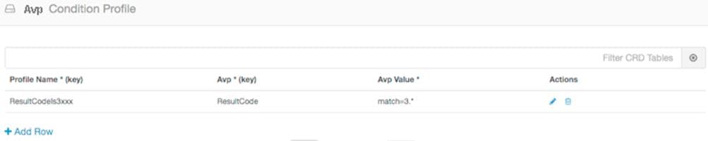
Avp Condition Profile
The Avp Condition profile is used to specify the value and condition to apply to AVP.
The following table describes the fields of Avp Condition Profile:
Table 1. Avp Condition Profile
Field
Description
Profile Name
Profile name of the condition.
Each row in the table is a condition. You can define multiple conditions for one Profile Name.
Avp
Avp that condition is applied to.
Avp Value
Value of the condition.
If there is no AVP, configure the value as AVP_IS_MISSING
Figure 2. Avp Condition Profile
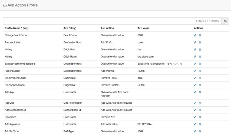
Avp Action Profile
You can use the Avp Action Profile to perform mediation at different directions (ingress, egress). You can modify both request
and response messages. You can replace, append, prepend value AVP. The value may be static or dynamically retrieved from another
AVP or can be extracted as substring from another AVP.
The following table describes the AVP actions that you can perform in Avp Action Profile:
Table 2. AVP Actions
Avp Action
Description
Remove Avp
Removes the AVP from the message.
Add with value
If the AVP is not present in the message, add the AVP with the value defined in CRD.
Add with Avp from Request
If the AVP is not present in the message, the AVP received from the request message is added to it.
Overwrite with value
Overwrite the AVP with the value defined in CRD.
Overwrite with Avp from Request
Overwrite the AVP with the AVP received from the request message
Add Prefix
Add prefix to the value of AVP.
Add Postfix
Add postfix to the value of AVP.
Remove Prefix
Remove prefix from the value of AVP.
Remove Postfix
Remove postfix from the value of AVP.
Figure 3. Avp Action Profile
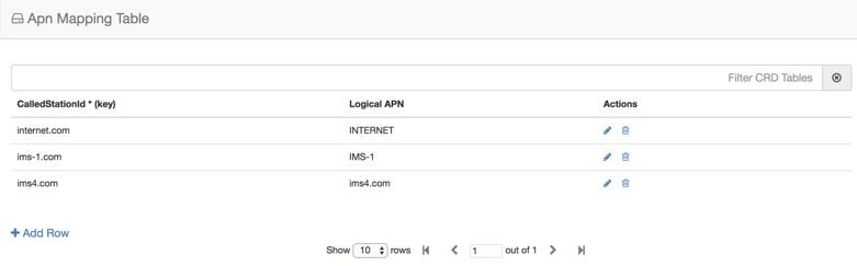
APN Mapping
Table
The APN consists of two parts which are as follows:
The APN Network
Identifier. This part of the APN is mandatory.
The APN Operator
Identifier. This part of the APN is optional.
The actual APN of any interface is filled-in with Called-Station-Id AVP. This table keeps a mapping of actual APNs and logical
APNs configured in the logical APN list.
The following is an example configuration:
Figure 4. APN Mapping
Table
The Called-Station-Id input is case insensitive where it stores all the values in lower case. It converts the upper case entry
to a lower case value and checks for a duplicate entry. If the input APN contains any duplicate value, it rejects the value
with an error message.
For example, if the input value is IMS.COM, it stores the value as ims.com.
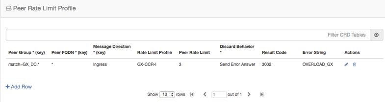
Peer Rate Limit
Profile
CPS vDRA can rate
limit traffic coming from and going towards a particular peer. This can work
for both Ingress and Egress traffic. User needs to define the peer group, FQDN,
traffic direction and the CPS vDRA behavior, whether to silently drop or send
error message. User can also define the error code and the error message when
error responses need to be sent back.
Figure 5. Peer Rate Limit
Profile
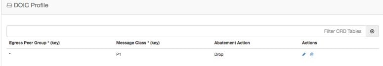
DOIC Profile
Use the DOIC Profile table to define the abatement action for Diameter messages in case of Diameter peer overload or congestion.
The following table describes the DOIC Profile table parameters:
Table 3. DOIC Profile
Fields
Description
Value
Egress Peer Group
Name of egress peer group.
Referenced from the Peer Group name in Peer Group SRK Mapping.
Message Class
Message classification.
Priority P0 is considered for emergency message class. Hence, it cannot be configured in DOIC for throttling.
In case abatement treatment is applicable for P0 message as per Loss Algorithm (with random number), the message is forwarded.
P1, P2, P3, P4
Abatement Action (output)
The abatement action to be taken by vDRA.
Divert, Forward, Drop
The following abatement actions are supported:
Forward: Forward allows the message to be sent to the destination peer, even though the peer is overloaded.
Divert: Messages are diverted to the non-congested secondary peer as found using Peer Group SRK Mapping. If the secondary
peer is congested, the next non-congested peer is used. If all peers are congested, the messages are dropped.
Drop: Message is throttled with error response 3002
When a message is throttled, a default result-code of 3002 and default message "Throttled due to DOIC congestion" is sent.
The error message can be configured in Error Result Code Profile table with the Error key as Doic Throttled/Dropped.
Default Error Message is “3002: 012 - Throttled due to DOIC congestion”
Figure 6. DOIC Profile
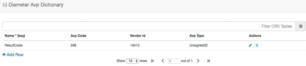
Diameter Avp Dictionary
Use the Diameter Avp Dictionary CRD table to define the AVP name, AVP code, vendor ID, and the type.
The following table describes the parameters of the Diameter Avp Dictionary:
Table 4. Diameter Avp Dictionary
Field
Description
Name
Name of the AVP.
Avp Code
Code of the AVP.
Vendor Id
Vendor ID not supported for regx pattern ,wild card entries (*) and it is a mandatory field.
Avp Type
Type of AVP (Integer32, Unsigned32, Integer64, OctetString, UTF8String, Grouped)
Figure 7. Diameter Avp Dictionary
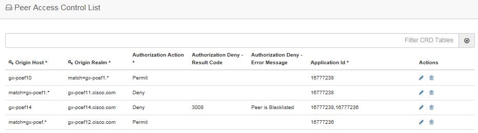
Peer Access Control List
You can use the Peer Access Control List to specify the list of peers (by realm, FQDN, application ID, or Source-IP) that
can establish peer connections to vDRA.
Peers that are not listed with realm or host in the CRD are allowed to establish peer connections by default.
Specify the following parameters:
The key fields are Origin Host and Origin realm, hence it is possible to have only one row for each unique pair.
Origin Host - Diameter identity or FQDN(host) of the client either in full or as a regular expression
Origin Realm - Diameter Identity or realm of the client either in full or as a regular expression
Source IP - Specifies the IP address or Subnet/Range that is expected in the Host-IP-Address AVP of the incoming Capabilities-Exchange-Request
(CER) message. The configuration formats include:
Specifc IP: Enter a specific IPv4 or IPv6 address. For example, 10.0.0.1.
Subnet: Enter a subnet range, ffor example, 10.0.0.0/24. The system will validate if the incoming IP falls within this range.
Wildcard: Enter * to allow any IP address.
Note
When source IP is configured as IP / IP Range (that is, subnet) only and wildcard (*) then, values gets stored directly in
the CRD without any modification.
IP/Subnet: When a specific IP or Subnet is configured, the system validates the format (identifying it as IPv4/IPv6 and Subnet).
This value is stored in the CRD and used for exact matching or subnet range verification against the incoming request.
When the entered Source-IP matches wildcard(*) then, the IP address validation and the value to store in CRD is skipped.
Wildcard (*): When * is configured, IP address format validation is skipped during processing. The value * is stored in the
CRD effectively bypassing the IP check for that entry (allowing all IPs).
Authorization Action: Specifies whether the incoming client connection is allowed or denied.
Authorization Deny - Result Code: Configurable result code. If not configured, the default value of 3010 (Unknown Application)
or 3007 (Unsupported Application) is sent. Applicable only when the Authorization action is set to “Deny”
Authorization Deny - Error Message: Configurable Message. If not configured default values are Unknown Peer or Unsupported
Application.
Applicable only when the Authorization action is set to “Deny”
Application ID: single, comma-separated, or regular expression.
If the peer connection is rejected due to mismatch of Applications, customized result-code / error messages are not applicable
in this case.
Figure 8. Peer Access Control List
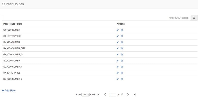
Peer Routes
Request forwarding is
done using Peer Routes to discover peers. These routes are different for
different interfaces. There can be multiple peer routes for a particular
interface.
Note
If multiple remote peers (having same FQDN) are connected with DRA and one remote peer goes down after sending a request then
response message is also dropped. DRA does not send the request to any other remote peers (having same FQDN).
Figure 9. Peer
Routes
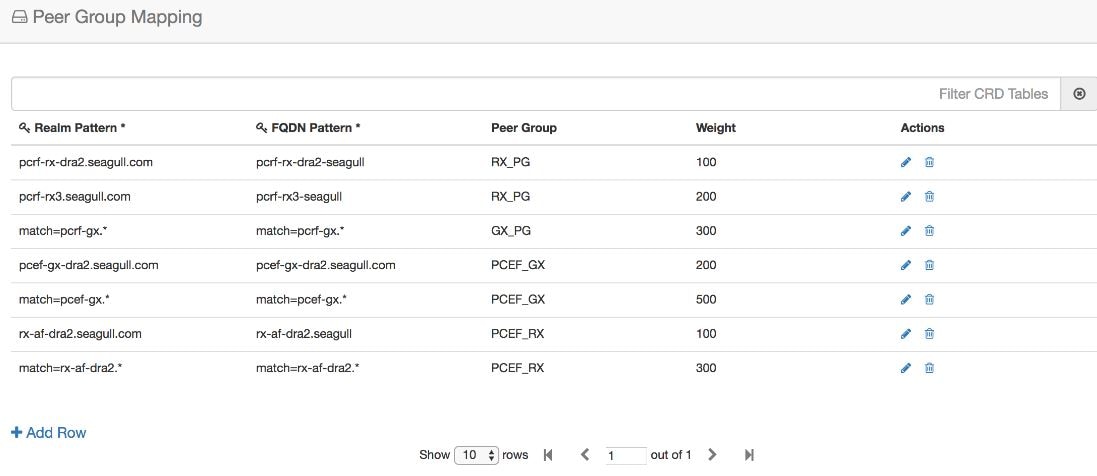
Peer Group
Mapping
One or more peers are
combined into single peer group based on their realms patterns and FQDN
patterns. Peer groups have respective peer routes.
Figure 10. Peer Group
Mapping
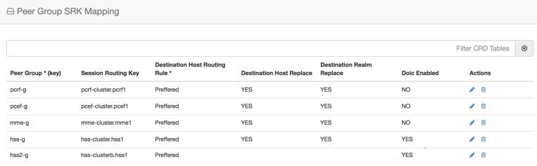
Peer Group SRK Mapping
All the peer groups consisting of one or more peers are listed in this table. Also various features like Session Key Routing
or Destination Host Routing can be configured as Only, Never, Preferred depending upon the need. Use the DOIC Enabled column
(YES/NO) to enable or disable Diameter Overload Indication Conveyance (DOIC). This option is used to throttle or divert Diameter
requests towards PCRF, HSS, AAA, and OCS servers based on reporting of overloaded conditions.
Figure 11. Peer Group SRK Mapping
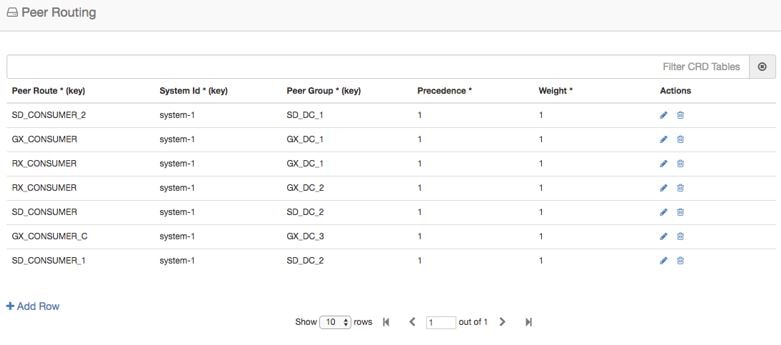
Peer Routing
This table consists of
a mapping of Peer Groups to Peer Routes on a particular CPS vDRA. It also has
precedence and weight columns which play a vital role in load balancing
behavior of CPS vDRA.
Figure 12. Peer
Routing
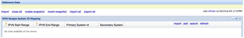
IPv6 Ranges System ID Mapping
Use this table to specify a range of IPv6 addresses and the primary and secondary vDRA system ID.
Figure 13. IPv6 Ranges System ID Mapping
Table 5. IPv6 Ranges System ID Mapping Fields
Fields
Description
IPV6 Start Range
Indicates the start of range in ASCII.
IPV6 End Range
Indicates the end of range in ASCII.
Primary System ID
Mandatory field. Indicates the System ID of vDRA in a vDRA cluster to which the request can be relayed.
Secondary System ID
Secondary vDRA System ID where lookup can happen.
Note
The ranges are expected to be mutually exclusive and unique. Verify the values when provisioning the same.
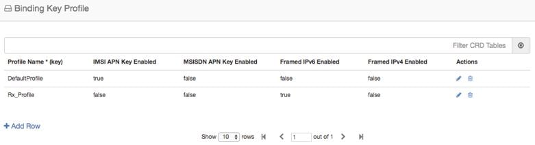
Binding Key
Profile
Important
For routing to work
in DRA, user must configure
AppId Key
Profile Mapping and
Binding Key
Profile tables.
The available fields
are Boolean fields and can be edited by selecting the check boxes.
Note
It is expected a
minimum of one row to be configured with the value “DefaultProfile”. This will
be used in case there is nothing configured for an application Id. For this
“DefaultProfile”, “imsiAPN” and “FramedIPv6Prefix” should be enabled.
Note
The field
MSISDN APN
Key Enabled is a place holder only. Modifying this field will not
have an effect on the application behavior.
Figure 14. Binding Key
Profile
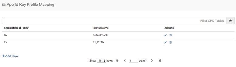
AppId Key Profile
Mapping
Important
For routing to work
in CPS vDRA, you must configure
AppId Key
Profile Mapping and
Binding Key
Profile tables.
Figure 15. AppId Key
Profile Mapping
The Binding Key
Profile column is tied to the Profile Name column from the previous CRD and
takes the available Profile Name in the system.
There are two
application Identifiers that have been provisioned in the system which are Gx
and Rx and can be tied to the same or different Bind Key Profile as the case
may be.
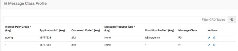
Message Class Profile
To determine the abatement action from the DOIC Profile table (for throttling or diverting Diameter requests), you require
a Message class. You can query the Message class from the Message Class Profile table.
The Message Class Profile table takes inputs such as Ingress Peer Group, Application Id, Command Code, Message/Request Type
and provides the Condition Profile and Message Class. Message Class can be one of P0, P1, P2, P3, P4.
Figure 16. Message Class Profile
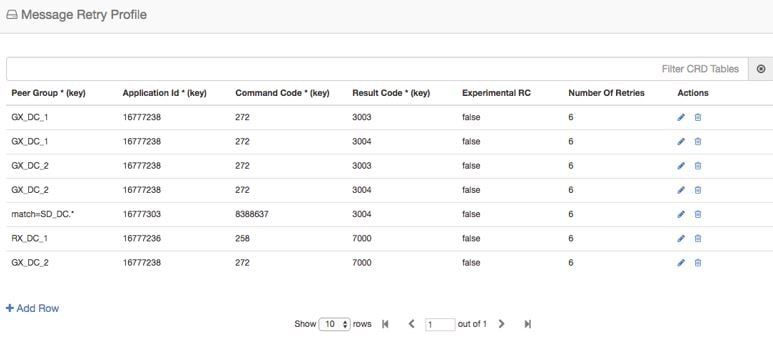
Message Retry
Profile
CPS vDRA supports
configurable retries, so that the specific behavior of CPS vDRA in congestion
scenarios can be configured.
Configurable retry
mechanism (i.e., number of retries) per:
Application ID
Peer Group
Answer Timeout
error occurred
Error Result Code
of Response
This should be in the
form of a CRD and applied to a peer group. The user can use the SRK peers to
select an alternate peer.
If all SRK peers
fail, the user should use one alternate CPS vDRA if it connects to the SRK. If
the SRK matches exactly, CPS vDRA would look for the second label match of SRK
like clusterb.dc1 and clusterc.dc1 and retry the message to other peer group.
Figure 17. Message Retry
Profile - Control Center
Wild card match is
supported for Peer Group, Application Id, Command Code, Result Code columns.
For example, 300.* supports all RC starting with 300.
* is supported to
allow all RC.
* is supported
for all peer groups.
Match = GX_DC_.*
is supported for groups starting with GX_DC
RC = 7000 is
interpreted as retry for timeout.
Experimental result
code is for future purposes and value in that column has no effect on retry
processing.
Note
Best
Match check box needs to be checked in Policy Builder if you want
to use the wildcard feature.
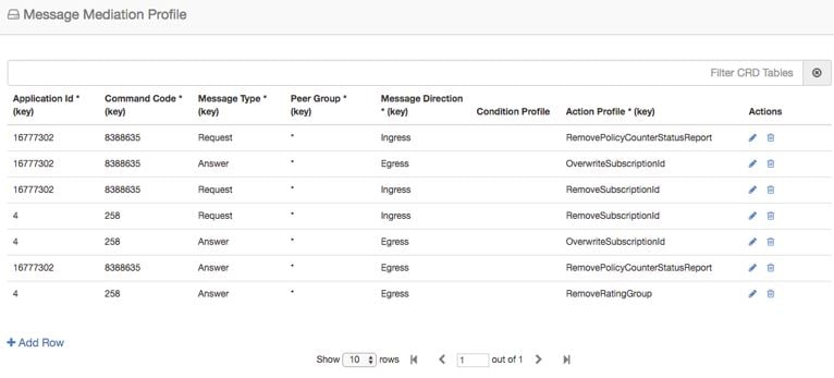
CPS vDRA supports message mediation profile for following use cases:
Store an AVP from the request and insert it into the answer. The answer is forwarded from an endpoint or an error generated
by CPS vDRA. The known use case for this is storing the MSISDN from a request from the OCS (Sy SNR, Gy RAR) and inserting
it in the answer to the OCS. The endpoint cannot handle all cases since the DRA can generate the error response in case of
request timeout or inability to route the request to a peer. The MSISDN is in the Subscription-ID AVP.
Remove an AVP from a request or answer.
Figure 18. Message Mediation Profile - Control Center
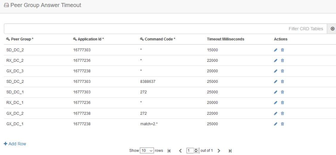
Peer Group Answer Timeout
CPS vDRA support for the following use cases:
Configurable answer timeout for initial try and subsequent retries for the following parameters:
Application ID
Peer Group (to which request is sent)
Command code (to enable different timeouts for different Diameter commands)
Timeout value (in milliseconds)
Default value if unspecified is 1700 milliseconds.
Peer group answer timeout is applicable for every message routed using:
Destination host routing
SRK routing
Table driven routing
Sample peer group answer timeout is shown below:
Figure 19. Peer Group Answer Timeout
Wild card match is supported for application_id, peer_group, command code. * indicates all application_id, peer_group.
The following rules have been applied for answer timeout:
Default timeout for any message routed from CPS vDRA is 1700 ms.
In case of retry, if an alternate group is chosen for routing, corresponding timeout for the peer group is applied.
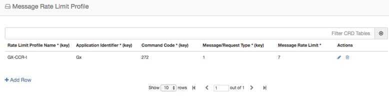
Further to peer level
rate limit, CPS vDRA provides the granularity of limiting diameter traffic at
message level for each peer. Message level rate limit always works in
conjunction with peer level rate limit and is an additional control in peer
level rate limit configuration. Since message level rate limit works in
conjunction with peer level rate limit, all the fields specified for peer level
rate limit are applicable to message level rate limit.
Message Rate Limit
Profile table is used to get the condition for such rate limiting. User can
define the type of message, command code and the application for which the
limiting has to be implemented.
Figure 20. Message Rate
Limit Profile
Dynamic Peer Rate Limit based on DB VM CPU Usage
Dynamic Peer Rate Throttling
Overload condition on binding databases occur when CCR-I or CCR-T bursts over one or more peer connections, thereby destabilizing
the system. To overcome the DB overload condition, DRA supports the following mechanisms to protect the system from such an
overload condition:
Dynamically vary peer message rate limits (CCR-I/T) based on DB CPU load to enable better utilization of available DB capacity.
Selectively throttle peer connections with traffic burst and continue processing of messages for peers with BAU traffic.
Configure Message Rate Limit Profile to throttle messages on the Director.and Rate limits for each message type in the profile.
Dynamic rate limiting allows you to:
Determine the available DB capacity and dynamically derive the rate limits.
Configure preferred rate limits and apply dynamic throttling on configured values.
Limitations
Following are the limitations:
Dynamic peer throttling feature applies only to peer connections with message rate limits configured on ingress direction.
Throttling impacts all CCR-I/T messages on a peer connection irrespective of whether the binding corresponding to the overloaded
DB is enabled.
If the maximum throttling percentage configured in the profile does not restore the DB CPU load to normal values, the system
remains in the same state until the overload condition clears.
Monitoring DB CPU Threshold
Important
Configure the binding shard-metadata-db-connection loadmetrics ip-address port command to monitor CPU usage of all database VMs:
For more information on binding shard-metadata-db-connection, see the binding shard-metadata-db-connection section in the CPS vDRA Operations Guide.
For dynamic DB throttling, DB VM CPU statistics is collected periodically (every 10 seconds) and stored in metrics database.
These statistics are cached by Workers and used to enforce dynamic DB throttling under high load conditions. But dynamically
modifying rate limits on directors require that DB VM CPU statistics are available to directors.
Since the Workers periodically retrieve and cache the required statistics, Workers can monitor for threshold violations and
notify Directors on the status. This eliminates the overhead on directors for retrieving the required statistics. Directors
then checks whether CPU thresholds are beached and start to reduce the rate limits of peer groups upon threshold breach.
Threshold monitoring and notification is processed on workers to:
Perform the threshold monitoring on one of elected Workers. If the elected worker fails, another worker takes over the function.
Ensure that the threshold status messages are received by directors at least once.
Ensure that the Worker publishes duplicate messages using different Control Plane Redis connections.
Not to notify the status of individual DB VM. This reduces the overhead on directors. Only following summary DB CPU status
will be notified:
Threshold breach
Normal
This results in one threshold status message from wWrker to Directors for every statistics polling period (10 seconds).
Since different peer groups are configured with different CPU thresholds, Worker uses the lowest CPU threshold to generate
threshold breach event. The threshold is compared against the highest CPU utilization value among all the DB VMs. Upon threshold
breach, corresponding event is published to Directors with highest observed CPU utilization. This ensures that Directors apply
throttling based on CPU utilization of most loaded DB VM.
Dynamic Throttling Configuration
Dynamic throttling of message rate limits requires configuring the DB VM thresholds and corresponding throttling percentage
to be applied. Specifying multiple thresholds with different throttling percentages enables varying the throttling based on
severity of overload condition. For example, consider three different thresholds such as minor, major, critical, and apply
throttling percentages increasing with severity.
During configuration of multiple thresholds, throttling applies corresponding to the highest threshold breached.
The following table describes the fields of Dynamic Throttling DB CPU Profile.
Table 6. Dynamic Throttling DB CPU Profile
Field
Description
Name
Name of the profile.
DB CPU Utilization Threshold
CPU utilization value in percentage beyond which throttling is applied.
Throttle Percentage
Throttling percentage that is applied on configured message rate limits. Rate limits are reduced by configured percentage.
To apply throttling profile to peers, use the following Dynamic Peer Rate Limit Profile parameters.
Table 7. Dynamic Peer Rate Limit Profile
Field
Description
Peer Group
Name of the origin peer group. Supports Wildcard values.
Peer FQDN
The origin peer FQDN.
Dynamic Throttling DB CPU Profile
Name of dynamic throttling DB CPU profile.
Dynamic throttling of message rate limits requires enabling of DRA Dynamic Peer Rate Limiter configuration in the Policy builder.
If this configuration is not enabled through the Policy Builder, then you cannot view any DB CPU control messages from Worker
to Director. For more information, see the Enable DRA Dynamic Peer Rate Limiter section.
Rules for Applying Dynamic Throttling for Peer Connections
Directors monitor DB CPU threshold events from Workers. Upon threshold breach, Directors evaluates the throttling profiles
applied to peers against the CPU utilization value and reduces the rate limits based on the threshold breached.
When there is a threshold breach following rules apply for throttling for a peer:
Dynamic rate limit throttling applies only to peers with message rate limit profile configured for CCR-I/CCR-T in ingress
direction.
If throttling is applied to peer but the new threshold breached is higher than previous threshold, vDRA evaluates the threshold
against the profile and applies throttling corresponding to the higher threshold. When revising the throttling, rate limits
are always calculated based on the base or preferred rate limits.
For example, consider the following configuration
Message Rate limit:100
Table 8. Example for Dynamic Throttling DB CPU Profile
Threshold
Throttling Percentage
50
20
55
30
60
40
65
50
If the DB CPU utilization is in the range of 50-55%, rate limits gets throttled by 20% and effective rate limit is 80. If
CPU utilization increases to 62%, then throttling of 50% is applied on configured rate limit of 100 and revised rate limit
will be 50.
If throttling is applied to peer and the new threshold breached is same or lower than previous threshold, then throttling
is upgraded to throttle percentage configured for the next higher threshold.
For example, consider the following configuration:
Message Rate Limit:100
Table 9. Example for Dynamic Throttling DB CPU Profile
Threshold
Throttling Percentage
50
20
55
30
60
40
65
50
When the DB VM CPU usage breaches 50%, throttling of 20% is applied and effective rate limit for all peer connections will
be 80
Throttling reduces the load and reduce the CPU usage to < 50%
If the load continues, then CPU usage will increase and breach 50% threshold again. Because throttling for 50% threshold has
already been applied, throttling increases to 30% corresponding to threshold 55%. Effective rate limits will be 70. If the
threshold breach continues, then throttling increases to 40% (threshold 60) and 50% (threshold 65). Once maximum throttling
of 50% has been applied, no further action takes place even if the threshold breach continues.
Dynamic throttling applies to all messages irrespective of whether the corresponding binding profile has binding corresponding
to overloaded DB enabled.
If throttling is not applied for the peer, apply throttling corresponding to the threshold breached.
Throttling Reversal
Once the CPU utilization of overloaded DB VM(s) falls and remains below the threshold for a hold time, reversal of rate limit
reduction is triggered. Configure the hold timer to trigger throttling reversal during normal load condition.
To prevent reversal action from creating a ping-pong effect, reversal will be performed in smaller steps. Throttling will
be reversed based on the Reversal Step in % values configured in the Policy Builder. At each step, vDRA monitors DB load for hold time before applying the next step. If reversal causes threshold breach, roll
back is performed.
Note
It is recommended to use smaller steps for reversal.
Resilliency
Resilliency supports the following functions:
Worker Node Restart or Failure During threshold monitoring and notification function of Worker node, if the Worker node fails or restarted, another worker
takes over the function. The Semaphore coordinates the role of threshold monitoring. Each Worker periodically (every 5 seconds)
tries to acquire a lock on the Semaphore for a duration of 10 seconds. The Worker that acquires the lock performs the threshold
monitoring function until it fails or is restarted:
Director Restart: To ensure that new peer connections to a restarted Director are throttled at startup under existing DB overload condition,
Director sends a threshold event query message to Worker. The Worker performing the threshold monitoring function responds
to the Director with the latest threshold event. The Director processes the Query response,which initiates the query. If DB
is overloaded throttling is applied and Query response gets ignored by rest of the Directors.
Enable DRA Dynamic Peer Rate Limiter
Configure the following parameters under DRA Configuration:
In the Policy Builder, on the right pane, click DRA Configuration.
In the DRA Configuration area, check the Dra Dynamic Peer Rate Limiter check box to enable the Dynamic throttling feature. By default this check box is disabled.
The following fields are available with default values, when you enable the Dra Dynamic Peer Rate Limiter parameter:
Reversal Hold Time (Seconds): Specifies reversal hold time. Default is 30 seconds.
Reversal Step in % : Specifies the reversal step. Default is 20%.
Note
Specify the Reversal step within 100% and do not enter decimal values.
Auto Apply Next Level Throttle: Check the Auto Apply Next Level Throttle check box to dynamically apply next level throttling only if the DB CPU is in the configured range.
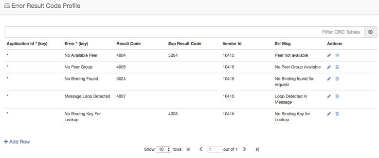
Error Result Code
Profile
Sample CRD data looks
like this:
Figure 21. Error Result
Code Profile
For any CPS vDRA
error or message timeout, CPS vDRAhas the ability to map the error to a
Result-Code value and an error message string for the Error-Message AVP.
Errors include
things like "binding not found", "message timeout", "no peer connections".
The Result Code
value is sent in the Result-Code AVP in the response.
The error message
string is sent in the Error-Message AVP in the response.
When both Result
Code and Exp Result Code are configured in this table, Result Code will take
precedence. In case Result Code is not configured in this table, Exp Result
Code will be sent with Vendor-ID.
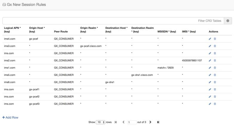
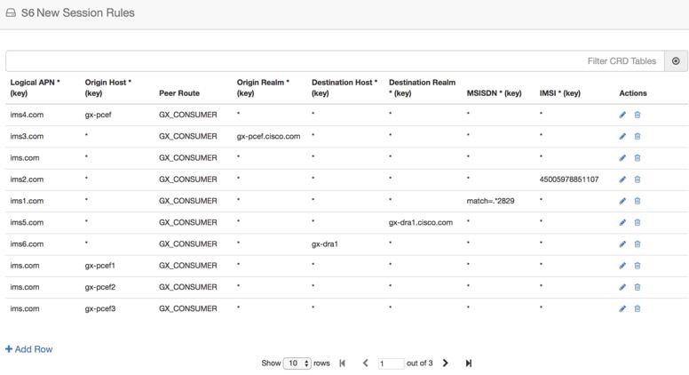
Gx New Session
Rules
Gx New Session Rules
table is used by CPS vDRA when performing Table Driven routing. CPS vDRA could
derive the "Peer Route" from this table, when the incoming message has no
destination host to be routed to. From peer route, CPS vDRA derives further
route where the request could be sent. This table supports both wildcard and
exact match for the various parameters. The "Peer Route" used in this table
should be defined in "Peer Routes" table. Here an example for Gx New Session
Rules is provided. Similar tables can be created for Rx or Sd.
Figure 22. Gx New Session
Rules
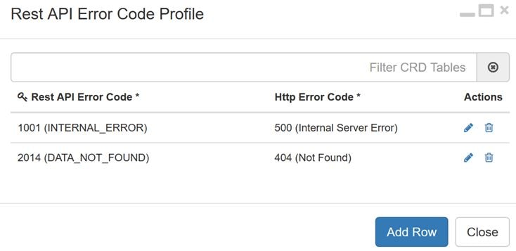
Rest API Error Code Profile
You can configure the HTTP response error code (such as 4xx, 5xx) corresponding to each vDRA Rest API JSON error response
code for the GET binding (for example imsi, imsiApn, msisdn, msisdnApn, ipv4, ipv6) Rest API.
This HTTP response code is used in the response for any GET binding Rest API request. If this CRD is not configured with HTTP
response codes, then vDRA returns the default HTTP response status code.
If you do not configure the Rest API HTTP Error Code in the CRD, vDRA uses the default HTTP error codes for GET binding Rest
API. For a list of the default HTTP error codes, see the CPS vDRA Troubleshooting Guide.
The following table describes the mandatory parameters in the Rest API Error Code profile CRD:
Table 10. Rest API Error Code Profile
Parameter
Description
Rest API Error Code
vDRA Rest API JSON error response code for the GET binding (for example imsi, imsiApn, msisdn, msisdnApn, ipv4, ipv6) Rest
API
Http Error Code
HTTP response error code (such as 4xx, 5xx) corresponding to each vDRA Rest API JSON error response code.
Figure 23. Rest API Error Code Profile
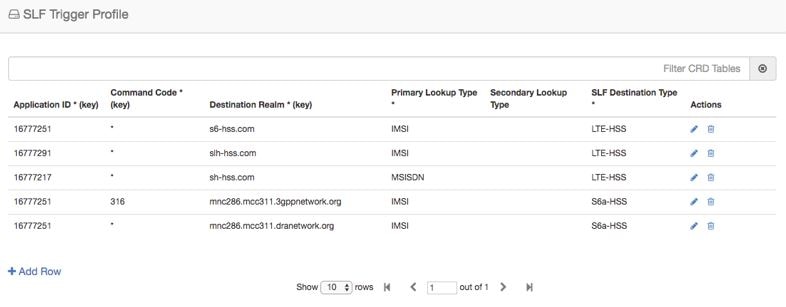
SLF Trigger
Profile
In this table, there
are three input keys: Application Id, Command Code and Destination Realm. If
all these input keys are matched from the Diameter incoming requests and
trigger condition for the SLF trigger table is matched, then CPS vDRA derives
the Primary Lookup Type (IMSI/MSISDN) and SLF Destination Type as output of SLF
trigger table. Then a query is made in the SLF Database using the Primary
Lookup Type (IMSI/MSISDN) and SLF-Destination-Type.
This table is used in
the case when the Diameter Request does not contain any “Destination-Host” AVP
or, in case the “Destination-Host” AVP comes with the Diameter Host Name of CPS
vDRA.
Figure 24. SLF Trigger
Profile
Based on Application
ID 16777251, Command Code 316 and Destination Realm of
ims.mnc286.mcc311.3gppnetwork.org, Primary Lookup Type
selected is IMSI and SLF Destination Type is selected as S6a-HSS. This Primary
Lookup Type and SLF Destination Type is used to query SLF database for the
configured lookup type.
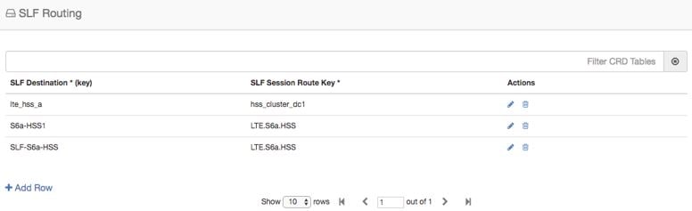
SLF Routing
This table contains
the mapping of SLF destination and the SRK of peer groups where the message
could be routed. The SLF destination is derived from SLF subscriber database.
Figure 25. SLF
Routing
S6/Sh Table Driven
Rules
This table is used
for table driven routing of S6/Sh messages when the destination host is not
available in the incoming request and there is no match SRK found in SLF
Trigger table/SLF Mapping table. Keys used for deriving the peer route are
Origin Host, Origin Realm, Destination Host, Destination Realm, MSISDN, IMSI
and the output is Peer Route.
An S6 Table Driven
Rules example configuration is given.
Figure 26. S6/Sh Table
Driven Rules
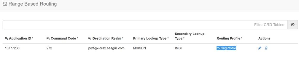
Range Based Routing
Important
This feature is not fully qualified in this release. It is available only for testing purposes.
For more information, contact your Cisco Accounts representative.
CPS vDRA provides range-based routing based on MSISDN and IMSI values so that Diameter requests are routed to the correct
HSS or AAA server. Range-based routing occurs if the destination-host routing, binding-based routing and SLF-based routing
fails.
vDRA checks whether the primary lookup type is IMSI or MSISDN and also checks whether the IMSI/MSISDN value present in the
request matches against the range configured in CRD.
The primary lookup type is evaluated first and if it fails, the secondary lookup type is evaluated.
If primary lookup type evaluation fails and if the secondary lookup type is not configured, the request is routed with table-driven
routing (if configured).
If both the primary lookup type credential and the secondary lookup type evaluation fail, the request is rejected or routed
with table driven routing (if configured).
vDRA matches the request against the Range Based Routing table and based on the result of the credential match, SRK routing
is initiated.
Table 11. Range Based Routing
Field
Description
Value
Application Id (input)
The diameter application of the message received
Integer value of the application id
Command Code (input)
The message command code
Integer value of the command code
Destination Realm (input)
The destination realm in the message
String value of destination realm
Primary Lookup Type (input)
Primary lookup type for range based routing
IMSI or MSISDN
Secondary Lookup Type (input)
Secondary lookup type for range based routing
NONE or IMSI or MSISDN
Routing Profile (output)
Routing profile
Any string value. (Should match the routing profile in either or both the IMSI and MSISDN range CRD for a successful match).
Figure 27. Range Based Routing
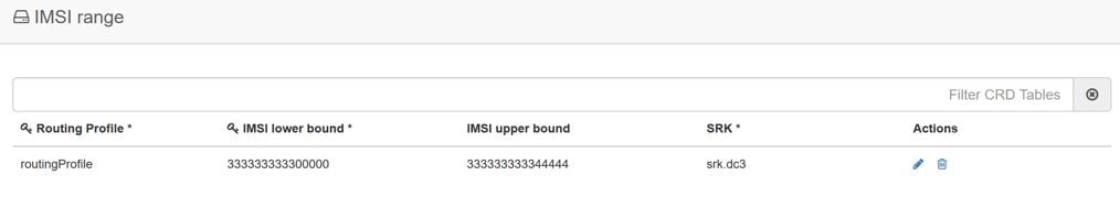
IMSI Range
The IMSI Range is used in range-based routing to configure the range of IMSI values.
Table 12. IMSI Range
Field
Description
Value
Routing Profile (input)
The routing profile name
Any string value
IMSI lower bound (input)
The lower bound for the IMSI value
For a numeric range, enter the IMSI value. For a regex, use the syntax: match=<regex>
IMSI upper bound (input)
The upper bound for the IMSI value
For a numeric range, enter the IMSI value. For a regex, leave it blank.
SRK (output)
The SRK key
Any string value
Examples:
For configuring numeric range between 9840510345 to 984059999: Lower bound: 9840510345, Upper bound: 9840598823
For configuring regex for numbers in range 9840500000 to 9840599999: Lower bound: match=98405[0-9]*, Upper bound : <leave
it empty>
For configuring regex for numbers in range 9840501333 to 9840502999: Lower bound: match=984050(1|2)[3-9]* , Upper bound :
<leave it empty>
For configuring regex for numbers in range 9840500000 to 9840599999: Lower bound: match=98405(([2-7][0-9]*)|(8[0-8][0-4][0-5][0-6])|(1[0-9][2-9][3-9][4-9])),
Upper bound : <leave it empty>
Figure 28. IMSI Range
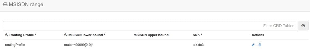
MSISDN Range
The MSISDN Range is used in range-based routing to configure the range of MSISDN values.
Table 13. MSISDN Range
Field
Description
Value
Routing Profile (input)
The routing profile name
Any string value
IMSI lower bound (input)
The lower bound for the IMSI value
For a numeric range, enter the IMSI value. For a regex, use the syntax: match=<regex>
IMSI upper bound (input)
The upper bound for the IMSI value
For a numeric range, enter the IMSI value. For a regex, leave it blank.
SRK (output)
The SRK key
Any string value
Examples:
For configuring numeric range between 9840510345 to 984059999: Lower bound: 9840510345, Upper bound: 9840598823
For configuring regex for numbers in range 9840500000 to 9840599999: Lower bound: match=98405[0-9]*, Upper bound : <leave
it empty>
For configuring regex for numbers in range 9840501333 to 9840502999: Lower bound: match=984050(1|2)[3-9]* , Upper bound :
<leave it empty>
For configuring regex for numbers in range 9840500000 to 9840599999: Lower bound: match=98405(([2-7][0-9]*)|(8[0-8][0-4][0-5][0-6])|(1[0-9][2-9][3-9][4-9])),
Upper bound : <leave it empty>
Figure 29. MSISDN Range
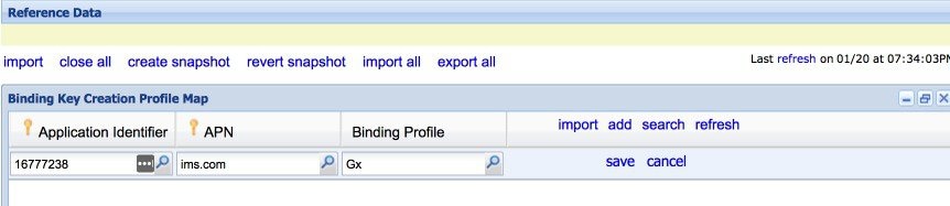
Binding Key Profile
Creation Map
The available fields are Boolean fields and you can edit them by selecting the check boxes.
Figure 30. Binding Key
Profile Creation Map
APN field supports both wildcard "*" and regex matches like "match=ims.*".
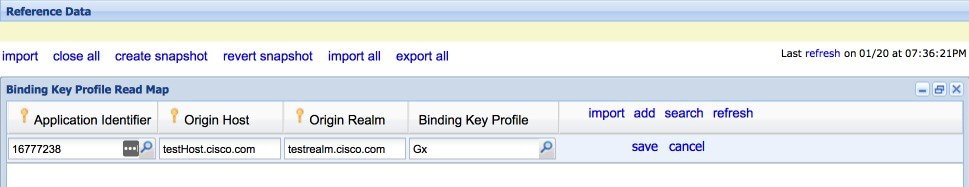
For Binding Key profile Read Map, both Origin-Host and Origin-Realm
support wildcard and regex match.
Binding Profile and Binding Key Profile fields use values from the Profile name field in Binding Key Profile table. Define
the profile using Binding Key Profile to create or read the tables.
The APN value is case insensitive which allows the input as a lower or upper case entry but converts the value to lower case
and stores it in the CRD table.
Binding Key Profile
Read Map
The available fields
are Boolean fields and can be edited by selecting the check boxes.
Figure 31. Binding Key
Profile Read Map
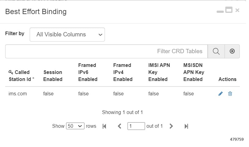
Best Effort Binding
This table enables you to configure best effort binding on APN basis. The Called-Station-Id is an unique key value on the
table that allows the values in lower case and accepts regular expressions.

 Feedback