Workgroup Bridge
Workgroup Bridge (WGB) is an Access Point (AP) mode that:
-
provides wireless connectivity to wired clients that are connected to the Ethernet port of the WGB AP,
-
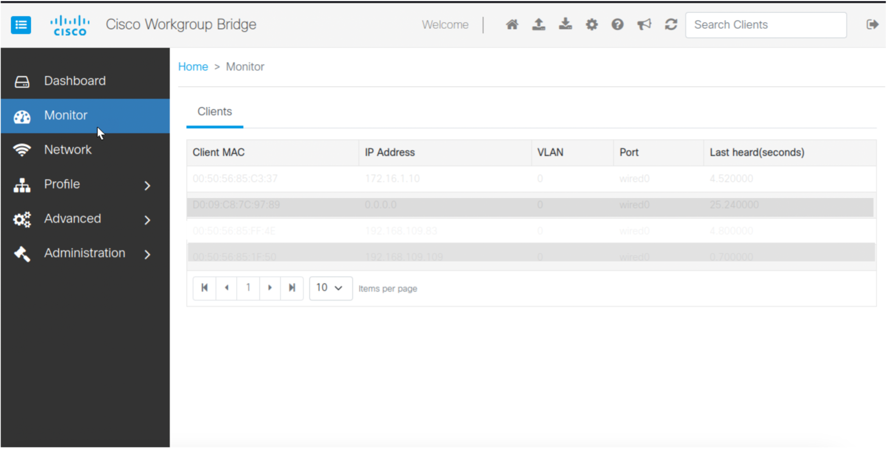
connects a wired network to a wireless segment by learning wired clients' MAC addresses on the Ethernet interface and reporting them to the wireless controller using Internet Access Point Protocol (IAPP) messages through an infrastructure AP, and
-
establishes a single wireless connection to the root AP, which in turn, treats the WGB as a wireless client.
For more details on WGB, see the chapter WGB.
|
Feature |
Release Information |
Feature Description |
|---|---|---|
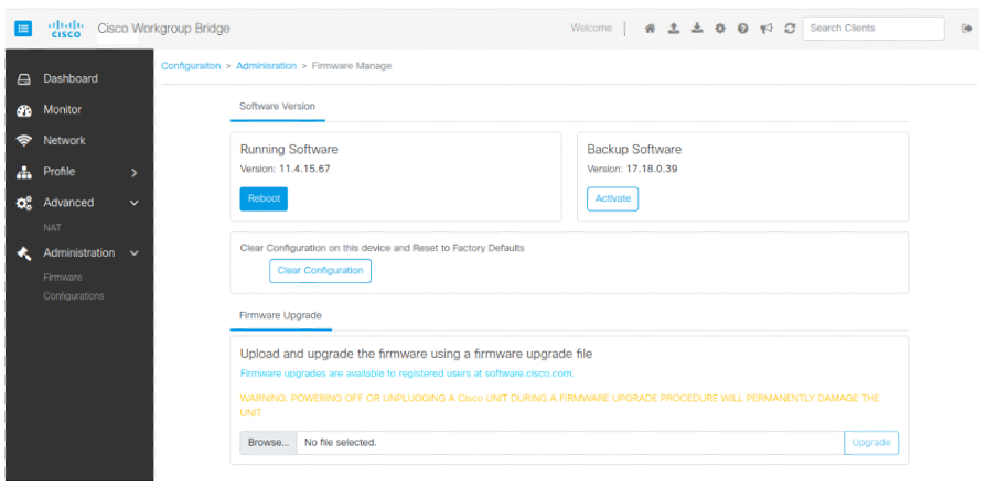
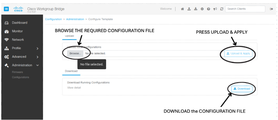
| Manage the Workgroup Bridges through Web UI | IOS XE 17.18.1 |
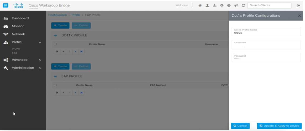
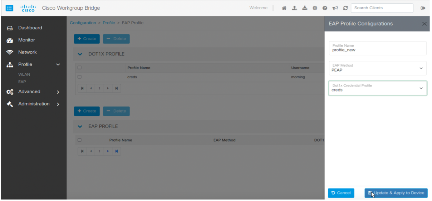
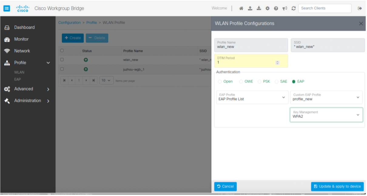
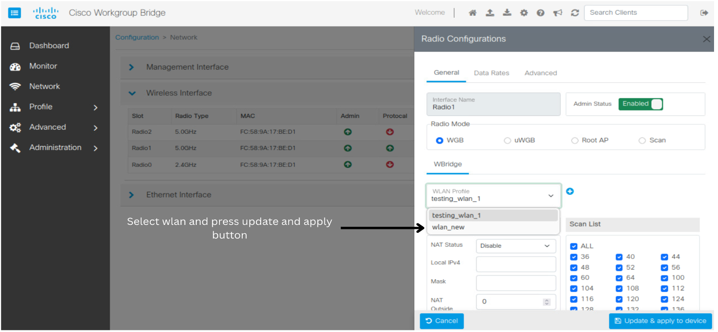
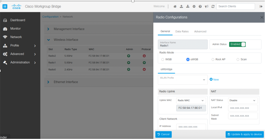
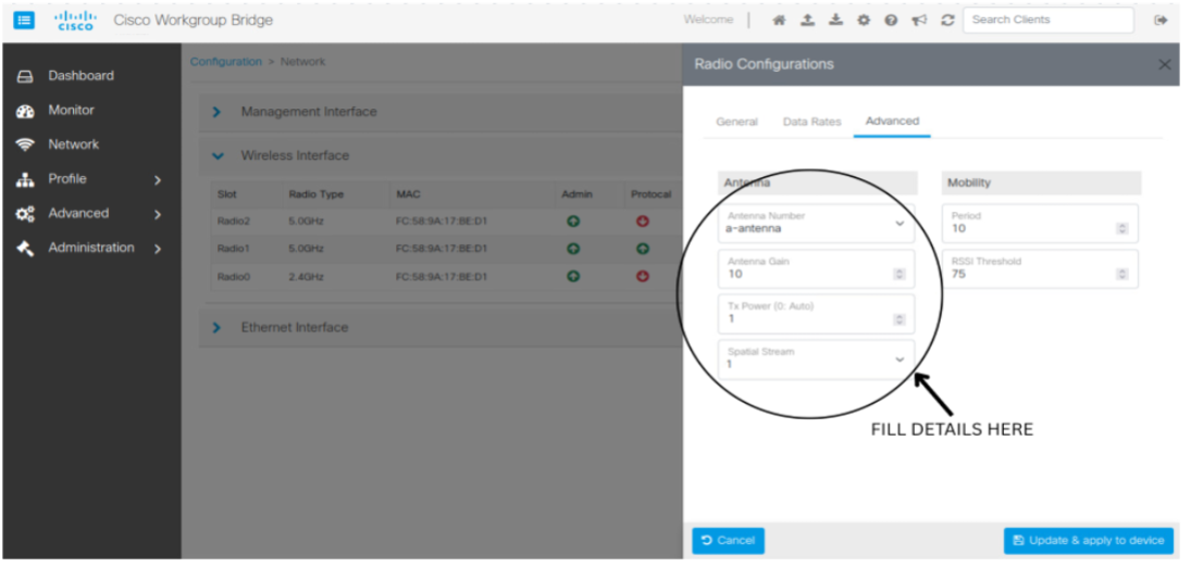
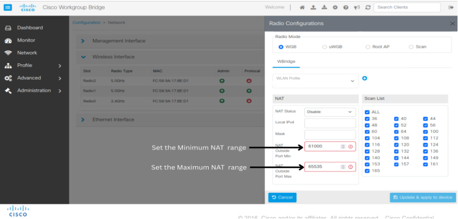
This feature enables you to configure the IW916X WGB through the Web UI. |
Cisco Web UI is a browser-based graphical user interface (GUI) that simplifies device setup, monitoring, and troubleshooting, making it particularly helpful for users unfamiliar with the Command-Line Interface (CLI).
 Feedback