Control and Provisioning of Wireless Access Points

Overview

CAPWAP is an IEEE standard protocol that enables a wireless LAN controller to manage multiple APs. It also allows Wireless LAN Controllers (WLCs) to exchange control and data plane information over a secure communication tunnel.

  • Operates at Layer 3 and requires IP addresses on both APs and WLCs.

  • Establishes tunnels on UDP ports 5246 (control) and 5247 (data) for IPv4 and IPv6, with DTLS encryption for security.

  • Allows centralized management of the wireless network and supports secure communication between APs and controllers.
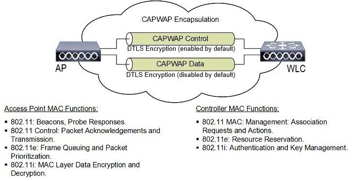
CAPWAP Protocol

CAPWAP uses DTLS to secure the control channel, encrypting all management and control traffic between the AP and WLC. The data channel is disabled by default. To enable CAPWAP data encryption, a DTLS license is required on the WLC and additional configuration is necessary on the AP.

  • DTLS ensures encrypted communication to prevent eavesdropping or tampering.

  • If an AP does not support DTLS data encryption, only the control plane is secured.

  • If an AP supports Data DTLS, it enables data DTLS after receiving configuration from the controller and performs a DTLS handshake on port 5247.

  • All data traffic between the AP and controller is encrypted after successful DTLS session establishment.

  • The IW9165E uses the IETF standard CAPWAP to communicate between the controller and other APs on the network.

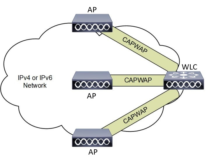
CAPWAP APs Connected to a WLC

This figure shows CAPWAP APs connected to a wireless LAN controller, illustrating the secure communication tunnel established between the APs and the WLC using CAPWAP and DTLS encryption.

Figure 1. CAPWAP APs connected to a WLC
CAPWAP APs connected to a WLC

Provisioning certificates on Lightweight Access Points

Certificate provisioning on a Lightweight Access Point (LAP) consists of several coordinated steps involving the LAP, controller, and certificate authority (CA).

Summary

The following actors and components participate in the certificate provisioning process:

  • LAP: Initiates the certificate request and installs the signed certificate.

  • Controller: Acts as a CA proxy and validates certificates during the JOIN process.

  • CA: Signs the certificate request forwarded by the controller.

This process ensures secure communication by provisioning and validating device certificates on the LAP.

Workflow

These stages describe the certificate provisioning workflow on a Lightweight Access Point (LAP):

  1. Certificate Request : The LAP sends a certificate request to the controller to get a signed X.509 certificate.
  2. CA Proxy : The controller acts as a CA proxy to facilitate the signing of the certificate request by the CA.
  3. Certificate Installation and Reboot : Both the LSC CA and the LAP device certificates are installed in the LAP, and the system reboots automatically.
  4. JOIN Request : After the reboot, the LAP sends the LSC device certificate to the controller as part of the JOIN request.
  5. JOIN Response and Validation : The controller sends the new device certificate and validates the inbound LAP certificate with the new CA root certificate as part of the JOIN response.

What’s next

Use LSC provisioning functionality to configure, authorize, and manage certificate enrollment with the existing PKI infrastructure for the controller and AP.

Understanding CAPWAP connectivity On AP

CAPWAP (Control and Provisioning of Wireless Access Points) is a protocol that enables APs to discover, join, and communicate securely with wireless controllers, supporting both split and local MAC operation modes.

  • Facilitates secure discovery and connection between APs and controllers using DTLS.

  • Supports two operational modes: Split MAC and Local MAC .

  • Enables centralized management of configuration, firmware, and user data traffic through control and data channels.

CAPWAP connectivity and operation details

CAPWAP connectivity involves a discovery phase, secure connection establishment, and management of AP configuration and data through dedicated channels.

  • APs initiate a discovery phase by sending discovery request messages to locate a controller.

  • Controllers respond with discovery responses, after which a secure DTLS connection is established.

  • APs send CAPWAP join requests and receive join responses to complete the joining process.

  • Controllers manage AP configuration, firmware, and control/data transactions post-join.

CAPWAP join process

This section describes the CAPWAP join process between an access point and a wireless LAN controller.

  1. Enable CAPWAP on the AP.

  2. AP sends discovery request to controller.

  3. Controller replies with discovery response.

  4. AP sends join request; controller sends join response.

  5. Secure DTLS connection is established for CAPWAP control and data messages.

CAPWAP communication between the access point and the wireless LAN controller is established over two logical channels, each serving a distinct function:

  • Control Channel: Used for configuration messages, image downloads, and client key exchanges. APs must acknowledge each message before sending the next.

  • Data Channel: Used for encapsulation and tunneling of user data traffic between APs and WLCs, enabling centralized policy enforcement and QoS.

Table 1. CAPWAP Operation Modes Comparison

Attributes

Split MAC

Local MAC

MAC Function Distribution

802.11 protocol split between AP and WLC

All MAC functions performed at AP

Data Frame Handling

Encapsulated and exchanged between WLC and AP

Locally bridged or tunneled as Ethernet frames

Management Frame Processing

Partially at AP, partially at WLC

Entirely at AP


Tip


In either mode, the AP processes Layer 2 wireless management frames locally before forwarding them to the controller.


Figure 2. Split MAC Architecture

Example: CAPWAP Join and Data Flow

For example, when a new AP is powered on, it sends a CAPWAP discovery request to locate a controller. After receiving a discovery response, the AP establishes a secure DTLS connection, sends a join request, and upon acceptance, the controller manages the AP’s configuration and data traffic through CAPWAP channels.

Reset button settings

The reset button on the IW9165E device allows users to perform different reset actions based on how long the button is pressed.

  • Pressing the reset button for less than 20 seconds performs a full reset.

  • Pressing the reset button for more than 20 seconds and less than 60 seconds performs a full factory reset (clears the FIPS flag).

  • The LED turns blinking red after the boot loader receives the reset signal.

Reset button operation details

To perform a reset, ensure you press the device's reset button before powering on the device. The LED will indicate the reset status by turning blinking red after the boot loader receives the reset signal.

Ethernet port usage on CAPWAP mode

The Catalyst IW9165E supports up to a 3.6 Gbps PHY data rate with two 2x2 multiple input and multiple output (MIMO) and two ethernet ports (2.5G mGig and 1G).

Catalyst IW9165E have below internal port mapping rules:

  • Wired0 – One mGig (2.5 Gbps) ethernet ports with 802.3af, 802.3at, 802.3bt PoE support.


    Note


    The wired0 port is used as CAPWAP uplink port in the AP local/Flexconnect mode.


  • Wired1 – 1Gig ethernet Lan Port.


    Note


    Starting from 17.14.1 release, RLAN feature is not supported in the wired1 port.


Indoor deployment

The indoor deployment mode for the IW9165E defines how the access point (AP) operates within supported regulatory domains, with specific default settings and frequency usage rules.

  • Supports both indoor and outdoor deployment for regulatory domains -B (USA), -E (EU), -A (Canada), and -Z (Australia, New Zealand).

  • By default, AP deployment mode is set to indoor.

  • For the -B domain, outdoor and indoor frequencies are the same.

Support for 6G power modes

The following table summarizes the support for 6G power modes based on AP deployment and 6G deployment modes.

Table 2. Radio 6G power mode support table

AP Deployment Mode

6G Deployment Mode

Low Power Indoor support

Standard Power support

Indoor AP

Outdoor

No

Yes


Note


Outdoor mode can be used indoors, but indoor mode cannot be used outdoors because 5150–5350 MHz channels are indoor-only in -E countries.


For more information about configuring AP deployment mode on the Wireless Controller, see Cisco Catalyst 9800 Series Wireless Controller Software Configuration Guide.

Verify indoor deployment

This procedure describes how to verify whether the indoor deployment is enabled or not on the WLC and AP.

This procedure helps you determine the indoor deployment status on both the Wireless LAN Controller (WLC) and Access Point (AP).

Procedure


Step 1

Run the show ap name ap-name config general | inc Indoor command on the WLC.

  • When indoor mode is enabled, the show command provides the following output:

    Device# show ap name ap-1 config general | inc Indoor
    AP Indoor Mode         : Enabled
                               
                                   
  • When indoor mode is disabled, the show command provides the following output:

    Device# show ap name ap-1 config general | inc Indoor
    AP Indoor Mode         : Disabled


Step 2

Run the show controllers Dot11Radio interface command on the AP to check the indoor deployment status.

  • When indoor mode is enabled, the show command provides the following output:

    Device# show controllers Dot11Radio 1
                                    …
    Radio Info Summary:
     =======================
    Radio: 5.0GHz
    Carrier Set:  (-Ei)( GB )
    Base radio MAC: FC:58:9A:15:B7:C0
    Supported Channels:
    36 40 44 48 52 56 60 64 100 104 108 112 116 120 124 128 132 136 140 

    Note


    In the command output, -Ei indicates the indoor mode is enabled.

  • When indoor mode is disabled, the show command provides the following output:

    Device# show controllers Dot11Radio 1
                                    …
    Radio Info Summary:
     =======================
    Radio: 5.0GHz
    Carrier Set:  (-E)( GB )
    Base radio MAC: FC:58:9A:15:B7:C0
    Supported Channels:
    36 40 44 48 52 56 60 64 100 104 108 112 116 120 124 128 132 136 140 

    Note


    In the command output, -E indicates that indoor mode is disabled.

The CLI output also shows the supported channels.


AP Radio Slot

The Cisco Catalyst IW9165E provides one dedicated 2x2 5GHz Wi-Fi radio and a Dual Band (XOR) radio that serves both 5 GHz and 6 GHz 2x2 radio bands.

  • Supports dedicated 5GHz Wi-Fi radio and Dual Band (XOR) radio for 5 GHz and 6 GHz bands.

  • Allows switching between 5G and 6G bands.

  • Admin state is disabled by default; Slot 2 XOR radio is fixed to 5G by default.

AP Radio Slots

To switch between 5G and 6G bands on the Catalyst IW9165E, use the following CLI command:

  • ap name <ap-name> dot11 dual-band band 6ghz/5ghz

Note


By default, admin state is disabled. Slot 2 XOR radio is fixed to 5G.


Table 3. AP Wi-Fi radio architecture modes

Mode

5 GHz Slot 1

5/6 GHz Slot 2

5G + 5G

5GHz 2x2:2SS (20/40/80 MHz)

5G 2x2:2SS (20/40/80/160 MHz)

5G + 6G

5GHz 2x2:2SS (20/40/80 MHz)

6G 2x2:2SS (20/40/80/160 MHz)

Supported fixed domains and country codes

The ROW regulatory domain simplifies the domain management of the manufacturing process for all the country codes that do not have a specific domain mapped.

Supported Fixed Domains

Domain

Country Codes

A

CA (Canada)

B

US (United States of America)

E

  • AT (Austria)

  • AT (Austria)

  • BE (Belgium)

  • BG (Bulgaria)

  • HR (Croatia)

  • CY (Cyprus)

  • CZ (Czech Republic)

  • DK (Denmark)

  • EE (Estonia)

  • FI (Finland)

  • FR (France)

  • DE (Germany)

  • GR (Greece)

  • HU Hungary)

  • IS (Iceland)

  • IE (Ireland)

  • IT (Italy)

  • LV (Latvia)

  • LI (Liechtenstein)

  • LT (Lithuania)

  • LU (Luxembourg)

  • MT (Malta)

  • NL (Netherlands)

  • NO (Norway)

  • PL (Poland)

  • PT (Portugal)

  • RO (Romania)

  • SK (Slovak Republic)

  • SI (Slovenia)

  • ES (Spain)

  • SE (Sweden), and

  • CH (Switzerland).

F

ID (Indonesia)

Q

JP (Japan)

Z

  • AU (Australia) and

  • NZ (New Zealand).

Catalyst IW9165 supported country codes (ROW)

Domain

Country Codes

ROW

  • CL (Chile)

  • KR (Korea, Republic of)

  • GB (United Kingdom), and

  • VN (Vietnam).


Note


You are responsible for ensuring APs approval for use in your country. To verify approval and to identify the regulatory domain associated with a particular country. For more information, see Cisco Product Approval Status .


Radio antenna settings

The Catalyst IW9165E radio antenna settings define how external antennas are connected and configured for optimal wireless performance.

  • The device supports four external antennas with RP-SMA (f) connectors.

  • Radio 1 connects to antenna ports 1 and 2; Radio 2 connects to antenna ports 3 and 4.

  • The IW9165E is compatible with Self Identifiable Antenna (SIA) antennas for the 6G band, with ports 1 and 3 supporting SIA antennas.

Supported antenna types and port assignments

The Catalyst IW9165E supports a range of external antennas and provides specific port assignments for each radio. SIA antennas are supported on select ports for the 6G band.

  • Four external antennas with RP-SMA (f) connectors

  • Radio 1: Antenna ports 1 and 2

  • Radio 2: Antenna ports 3 and 4

  • SIA antennas supported on ports 1 and 3 for the 6G band

  • Compatible SIA antennas: IW-ANT-OMV-2567-N and IW-ANT-OMH-2567-N

Comparison of antenna gain values for each slot is shown in this table.

Table 4. Antenna gain (dBm)

5 GHz Slot 1

5 GHz Slot 2

6 GHz Slot 2

3 4 7 8 10 13 15

3 4 7 8 10 13 15

7


Note


A power cycle is mandatory after the first installation of the SIA antenna.


For more information on antennas, see the Cisco Catalyst IW9165E Rugged Access Point and Wireless Client Hardware Installation Guide .

This example demonstrates how to verify the SIA status on the controller using CLI commands. Run the show ap config slots <AP> command to display SIA information.

Device# show ap config slots AP2CF8.9B1C.CE78 Cisco AP Name : AP4C42.1E51.A144 Attributes for Slot 2 SIA Status : Present(RPTNC) SIA Product ID : IW-ANT-OMV-2567-N

AFC support for 6 GHz Standard Power mode

The 6 GHz Standard Power mode is a regulatory-compliant operational mode for access points (APs) that requires coordination through an Automated Frequency Coordination (AFC) system.

  • Standard Power APs must obtain available frequencies and power levels from the AFC system before operation.

  • The AFC system determines allowable frequencies and maximum power based on regulatory body data (such as FCC for the U.S.).

  • Transmission power is limited to a maximum of 36 dB EIRP, and APs are permitted in UNII-5 and UNII-7 bands in the -B (U.S) domain.

Standard power mode operation and deployment

The Cisco Catalyst IW9165E supports AFC 6 GHz Standard Power mode, enabling APs to operate in outdoor environments with regulatory compliance. The AFC system computes available frequencies and power, and coordinates AP operation to avoid interference.

Table 5. Radio 6 GHz Power Mode Support

AP Deployment Mode

6G Deployment Mode

Low-power Indoor Support

Standard Power Support

Indoor AP

Outdoor

No

Yes

Table 6. 6 GHz Target Power

Max Conducted per Path Power

(SP/AFC)

Antenna Gain

Tx x Rx Chains

Max EIRP

(SP/AFC)

20-80Mhz

160Mhz

17 dBm

17 dBm

7 dBi

2x2

27 dBm

Verify AFC status on an AP

This procedure describes how to verify the AFC request and response data, as well as the current operating power mode, on an AP using commands.

Procedure


Step 1

Use the show rrm afc command to verify the AFC request and response data on the AP.

Example:

Device# show rrm afc

Location Type: 1
Deployment Type: 2
Height: 129
Uncertainty: 5
Height Type: 0
Request Status: 5
Request Status Timestamp: 2023-08-31T06:20:17Z
Request Id Sent: 5546388983266789933
Ellipse 1: longitude: -121.935066 latitude: 37.512830 major axis: 43 minor axis:
9 orientation: 36.818100
AFC Response Request ID: 5546388983266789933
AFC Response Ruleset ID: US_47_CFR_PART_15_SUBPART_E
                    

Step 2

Use the show controllers dot11Radio 2 | i Radio command to verify the current operating power mode.

Example:

Device# show controllers dot11Radio 2 | i Radio
Dot11Radio2     Link encap:Ethernet  HWaddr 24:16:1B:F8:06:C0
Radio Info Summary:
Radio: 6.0GHz (SP)
                    

GNSS support

Global Navigation Satellite System (GNSS) is supported on IW9165E. The AP tracks GPS information for devices deployed in the outdoor environment and sends the GNSS information to the wireless controller.

You can use this command to display the GNSS information on the AP:

AP# show gnss info
            

You can use these command to display the GPS location of the AP:

Controller# show ap geolocation summary
            
Controller# show ap name <Cisco AP> geolocation detail
            

Antenna Disconnection Detection

Antenna Disconnection Detection is a feature that monitors the signal strength delta across antennas on an access point to identify impaired or disconnected antennas.

  • Improves performance and reliability by using multiple antennas for better signal reception.

  • Detects antenna issues based on signal strength differences exceeding a defined threshold for a specific duration.

  • Notifies the system through IAPP messages and controller logs when an antenna issue is detected.

How Antenna Disconnection Detection Works

Multiple antennas on the transmitter and receiver of an access point (AP) enhance performance and reliability by selecting or combining the strongest signals. Detecting an impaired or physically broken antenna is critical to AP reliability.

The Antenna Disconnection Detection feature operates by monitoring the signal strength delta across the antennas on the receiver. If the delta exceeds a defined limit for a specific duration, the antenna is flagged as having issues.

  • Improved reception through antenna diversity.

  • Critical detection of antenna impairment or breakage.

  • Automated notification via IAPP messages and controller logs.

For more information about configuring Antenna Disconnection Detection on the Wireless Controller, see Cisco Catalyst 9800 Series Wireless Controller Software Configuration Guide .

Verify Antenna Disconnection Detection on an AP or AP Profile

This procedure describes how to ensure that APs are operating with properly connected antennas. Verifying this configuration can help diagnose connectivity or coverage issues.

Procedure


Step 1

Use the show ap nameap-name config general command to verify the configuration on an AP.

Example:

Conroller# show ap name AP4C42.1E51.A144 config general

Cisco AP Name   : AP4C42.1E51.A144
=================================================
Cisco AP Identifier                             : 8c84.4292.f840
Country Code                                    : Multiple Countries : US,CN,GB,HK,DE,IN,CZ,NZ
Regulatory Domain Allowed by Country            : 802.11bg:-ACE^   802.11a:-ABCDEHNSZ^   802.11 6GHz:-BEZ^
Radio Authority IDs                             : None
AP Country Code                                 : CZ  - Czech Republic
AP Regulatory Domain
802.11bg                                      : -E
802.11a                                       : -E
MAC Address                                     : 8c84.4292.f840
IP Address Configuration                        : DHCP
IP Address                                      : 9.9.33.3
IP Netmask                                      : 255.255.255.0
Gateway IP Address                              : 9.9.33.1
Fallback IP Address Being Used                  : 
Domain                                          : 
Name Server                                     : 
CAPWAP Path MTU                                 : 1485
Capwap Active Window Size                       : 1
                    

Step 2

Use the show ap profile nameap-profile detailed command to verify th detailed configuration parameters of a specific access point profile on the controller.

Example:

Controller# show ap profile name ap-profile detailed

AP Profile Name: ap-profile
.
.
.
AP broken antenna detection:
Status                                                 : ENABLED
RSSI threshold                                         : 40
Weak RSSI                                              : -80
Detection Time                                         : 120
                    

Troubleshooting

The document provides use cases to understand the reason for the Control and Provisioning of Wireless Access Points (CAPWAP)/Lightweight Access Point Protocol (LWAPP) tunnel break between Access Points (APs) and the Wireless Controller.

For more information, see Troubleshoot Access Point Disassociation from Controller


Note


There could be some changes in the software or hardware that can cause commands to stop working, the syntax to change, or GUIs and CLIs to look different from one release to another.


Feedback request

Your input helps. A key aspect to improving these support documents is customer feedback. Note that these documents are owned and maintained by multiple teams within Cisco. If you find an issue specific to the document (unclear, confusing, information missing, etc):

  • Provide feedback using the Feedback button located at the right panel of the corresponding article. The document owner will be notified, and will either update the article, or flag it for removal.

  • Include information regarding the section, area, or issue you had with the document and what could be improved. Provide as much detail as possible.

Disclaimer and caution

The information in this document was created from the devices in a specific lab environment. All of the devices used in this document started with a cleared (default) configuration. If your network is live, ensure that you understand the potential impact of any command.