Manage the Workgroup Bridges through Web UI

Workgroup Bridge

Workgroup Bridge (WGB) is an Access Point (AP) mode that:

  • provides wireless connectivity to wired clients that are connected to the Ethernet port of the WGB AP,

  • connects a wired network to a wireless segment by learning wired clients' MAC addresses on the Ethernet interface and reporting them to the wireless controller using Internet Access Point Protocol (IAPP) messages through an infrastructure AP, and

  • establishes a single wireless connection to the root AP, which in turn, treats the WGB as a wireless client.

For more details on WGB, see the chapter WGB.

Table 1. Feature History Table

Feature

Release Information

Feature Description

Manage the Workgroup Bridges through Web UI IOS XE 17.18.1

This feature enables you to configure the IW916X WGB through the Web UI.

Cisco Web UI is a browser-based graphical user interface (GUI) that simplifies device setup, monitoring, and troubleshooting, making it particularly helpful for users unfamiliar with the Command-Line Interface (CLI).
Access Cisco Workgroup Bridge

Before you begin

Ensure your WGB switch has a wired client and is reachable on the 192.168.0.x network.

Configure the wired client and switch to access the Cisco WGB Web UI at its default IP address (192.168.0.10).

Perform these steps to access the Cisco WGB Web UI dashboard.

Procedure


Step 1

Access the Cisco WGB Web UI using a browser. Enter the IP address 192.168.0.10 and log in with the default credentials:

  • username—Cisco

  • password—Cisco

The Cisco WGB Web UI redirects you to its homepage. Verify the client IP address to ensure that the wired client and the Cisco WGB switch are on the 192.168.0.x network.

Step 2

Ping 192.168.0.10 from the client to verify connectivity.

Step 3

Update the explicit login credentials.

Step 4

Login using the new credentials to access the Cisco WGB Web UI.


Monitor client details and configurations

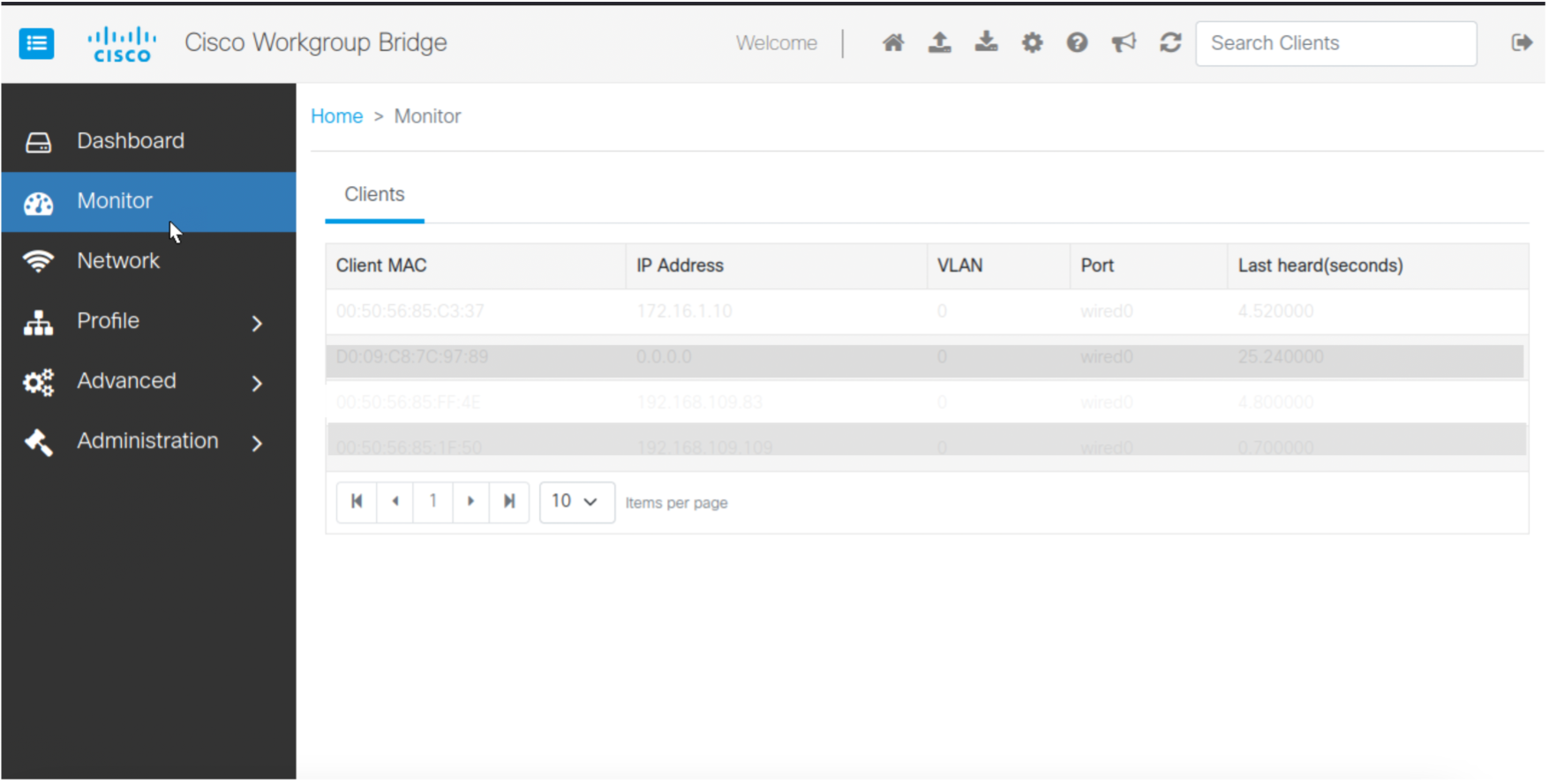
You can track the live activity and device connectivity to troubleshoot issues and ensure seamless network connectivity. This can be achieved by monitoring the client details such as Client MAC Address, IP address, VLAN details, Port and Last Heard Time (in seconds).

Perform these steps to monior the client details.

Procedure


Step 1

From Cisco WGB Web UI, choose Monitor to view the client details.

Step 2

Choose a number from the Items per page drop-down to set how many client entries appear on each page.


Configure and authenticate wireless profiles

A wireless profile is a pre-configured set of network settings that allows:

  • devices to connect to a wireless network automatically without manual reconfiguration,

  • storage of network details such as SSID, security type, encryption method, and passphrase,

  • minimization of errors in entering credentials, ensuring secure and consistent connections,

  • simplified distribution and management of network settings across multiple devices, and

  • easy switching between saved networks, such as home, office, or public Wi-Fi.

Create WLAN

You can create Wireless Local Area Network (WLAN) to provide wireless connectivity within a specific area, enabling devices to connect to the network without physical cables. WLANs enhance mobility by allowing users to move freely within the network's coverage area while maintaining connectivity. They reduce the need for extensive cabling, simplifies setup, and lower costs.

Before you begin

Configure Extensible Authentication Protocol (EAP), if you access multiple SSID.

Perform these steps to create WLAN.

Procedure


Step 1

Choose Profile > WLAN .

Step 2

Click Create.

Step 3

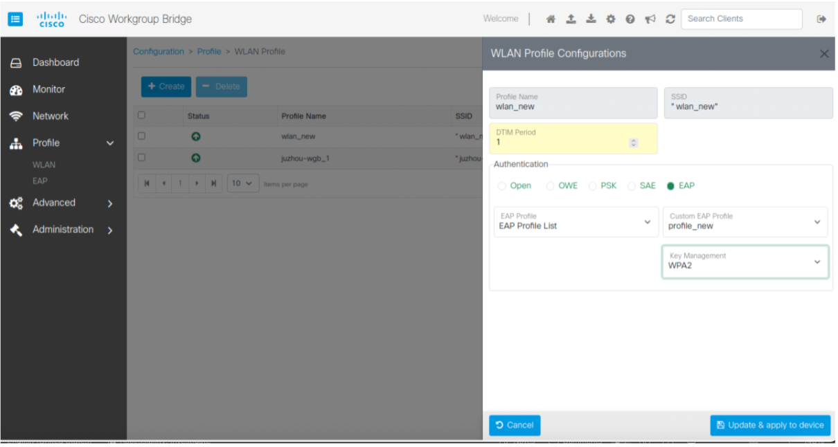
Select Authentication in WLAN Profile Configurations.

The Authentication types are:

  • Open: It provides access to networks without a password.

  • OWE: Opportunistic Wireless Encryption (OWE) provides automatic encryption for open networks without a password.

  • PSK: Pre-Shared Key (PSK) secures networks using a shared password for authentication and encryption.

  • SAE: Simultaneous Authentication of Equals (SAE) secures networks with strong password-based authentication and encryption.

  • EAP: Extensible Authentication Protocol (EAP) supports various authentication methods.

    You can configure EAP in WLAN either in Default EAP Profile or EAP Profile List. For details on EAP Profile configuration, see Create EAP profile.

    To select the EAP Profile List, you need to provide tUsername, Password, and Key Management information. For more details, see Map Extensible Authentication Protocol profile to Service Set Identifier.

Step 4

Update the required Key Management details based on Authentication.

The Key Management types are:

  • dot11r: 802.11r (Fast Transition)

  • dot11w: 802.11w (Protected Management Frames)

  • WPA2: secures Wi-Fi with AES encryption.

  • WAP3: enhances Wi-Fi with stronger encryption and password security.

Step 5

Click Update & apply to device.


EAP profiles and SSID maps

You can use EAP profiles to define secure authentication methods (example: Protected Extensible Authentication Protocol (PEAP), Extensible Authentication Protocol - Transport Layer Security (EAP-TLS)) for validating users or devices on a wireless network. Similarly, you can configure SSID maps to associate network names (SSIDs) with specific policies, VLANs, or EAP profiles. Together, they ensure secure access, proper segmentation, and efficient network management.

Create EAP profile

To securely authenticate users and devices in networks, EAP is required as it provides robust access control and data protection. EAP is essential for IIoT ecosystems that require scalable and secure device authentication. It offers flexibility and multiple authentication methods, which are critical for network security and safeguarding sensitive data.

Before you begin
Configure 802.1x profile. For more details see, Create 802.1X profile.

Perform these steps to create EAP profile.

Procedure

Step 1

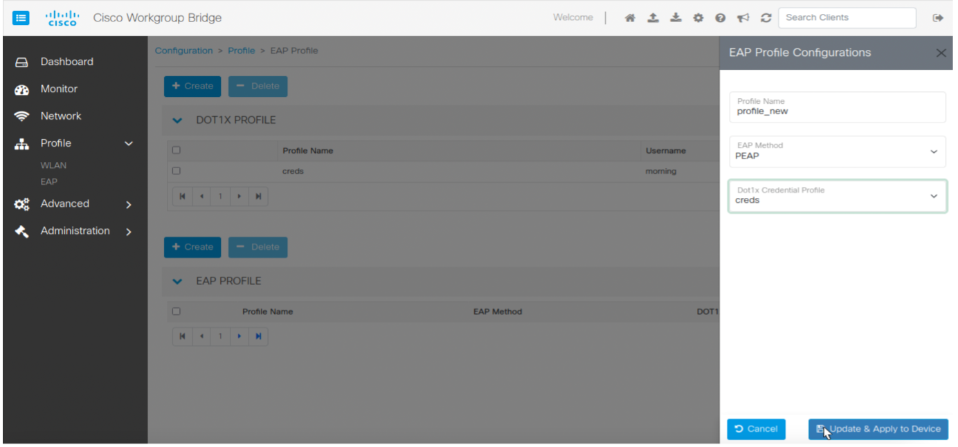
Choose Profile > EAP.

Step 2

Click Create in EAP PROFILE area.

Step 3

Update the Profile Name, EAP Method and Dot1x Credential Profile in EAP Profile Configurations .

Step 4

Click Update & Apply to Device.


Map Extensible Authentication Protocol profile to Service Set Identifier

Mapping the Extensible Authentication Protocol (EAP) to an Service Set Identifier (SSID) provides secure and authenticated access for devices connecting to the wireless network.

Perform these steps to map EAP profile to SSID.

Procedure

Step 1

Choose Profile > WLAN.

Step 2

Click Create.

Step 3

Update Profile Name and DTIM Period.

Step 4

Select EAP in Authentication.

Step 5

Select the Profile Name provided while creating the EAP in EAP Profile from the drop-down.

Step 6

Select Key Management from the drop-down.

Step 7

Click Update & apply to device.


Create 802.1X profile

You can use a 802.1X Profile to define authentication settings for IEEE 802.1X, enabling secure, controlled, and authenticated network access for users and devices.

Perform these steps to create 802.1X profile.

Procedure

Step 1

Choose Profile > EAP.

Step 2

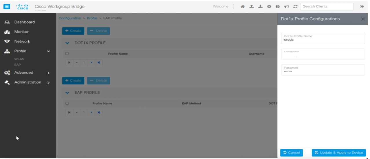
Click Create in DOT1x PROFILE area.

Step 3

Enter Dot1x Profile Name, Username and Password.

Step 4

Click Update & Apply to Device.


Pre-requisites for uWGB mode configuration

You can add a route to the NAT wired client to access the WebUI in uWGB mode via private LAN port.

Configure these commands on the linux client.

Procedure


Step 1

sudo ifconfig ens192 172.16.1.10 netmask 255.255.255.0

ens192—NAT wired client interface.

172.16.1.10—IP address of NAT wired client.

Step 2

sudo ip route add 172.16.1.0/24 dev ens192

Step 3

sudo ip route add 192.168.109.0/24 via 172.16.1.11 dev ens192

The Cisco WGB Web UI for uWGB can be accessed from NAT wired client.

172.16.1.11—Configure WGB LAN port in WLAN > Radio Configuration > uWGB mode > NAT.

192.168.109.0—Outside network IP address.

Once the uWGB mode is configured, the Cisco WGB Web UI can be accessed with the IP address (172.16.1.11) from the NAT wired client.

Creat a NAT rule to access uWGB mode. For details on NAT rules creation, see Create Network Address Translation rules.


Configure WGB and uWGB radio modes

The radio mode on the Cisco IoT Workgroup Bridge (IW916x) can be configured to operate in one of tthese wo distinct modes:

The mode selection depends on the type of Root Access Point (RAP) in the network infrastructure and is designed to ensure compatibility and seamless connectivity

Configure WGB mode on the radio

You can optimize network configurations and improve operational efficiency by switching to WGB mode. In this mode, the WGB uses Cisco's proprietary protocol extensions for enhanced performance and features. This mode is ideal for Cisco infrastructure deployments. If the Root Access Point (RAP) is a Cisco Access Point, setting the Radio Mode to WGB enables full use of Cisco-specific enhancements.

Perform these steps to configure WGB mode.

Procedure


Step 1

From Cisco WGB Web UI, choose Network.

Step 2

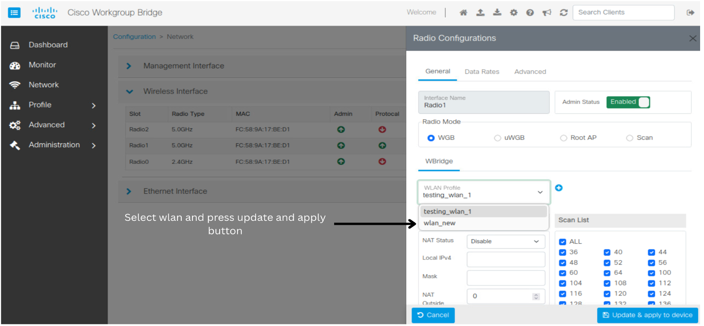
Select a desired radio from the list of available Wireless Interface.

Step 3

Select WGB in Radio Mode > Radio Configurations.

The radio modes can be changed to any mode like WGB, uWGB, Root AP or Scan mode.


Configure uWGB mode on the radio

You can optimize network configurations and enhance operational efficiency by switching to uWGB mode. In this mode, the WGB operates using standard protocols for universal compatibility, enabling seamless integration with non-Cisco Access Points (APs). This mode ensures interoperability in mixed-vendor environments. If the Root Access Point (RAP) is a non-Cisco AP, setting the Radio Mode to uWGB ensures universal compatibility and reliable connectivity.

Once you configure, use the WGB private LAN port address from NAT wired client to access the WebUI in uWGB mode. For detailed information about NAPT on uWGB, see NAPT on uWGB.

Before you begin

Configure WGB radio modes. For more details, see Pre-requisite for uWGB mode configuration.

To access or manage the WebUI in uWGB mode, configure the device with Network Address port translation (NAPT). To configure NAPT on the uWGB, perform these steps.

Procedure


Step 1

From Cisco WGB Web UI, choose Network.

Step 2

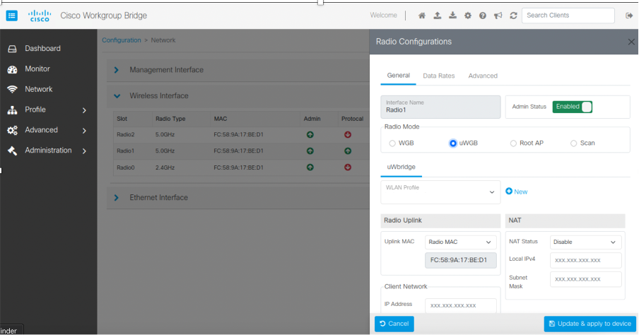
Select a desired radio from the list of available Wireless Interface.

Step 3

Select uWGB in Radio Mode > Radio Configurations.

The radio modes can be changed to any mode like WGB, uWGB, Root AP or Scan mode.

Step 4

Choose Radio MAC from drop-down.

Enter client MAC.

Step 5

Choose NAT Status from NAT drop-down.

Step 6

Enter the IP address of the NAT wired client in the Local IPv4 field to access the web UI.

Step 7

Click Update & apply to device.


Set IP address

The IP address used for accessing Cisco WGB Web UI can be set as either static or through DHCP to enhance the operational efficiency. With this approach, you can switch from:

  • static IP to dynamic IP,

  • dynamic IP to static IP

Switch from static IP to dynamic IP

You can switch from a static IP to dynamic IP allocation to enable automatic IP address assignment. This simplifies network management by removing the need for manual configuration and reduces the risk of IP conflicts. It also helps conserve IP resources by dynamically assigning addresses only when devices are connected

Perform these steps to change static IP address to dynamic IP address.

Procedure


Step 1

Choose Network > Management Interface.

Step 2

Select auxiliary-client .

Step 3

Change Static to DHCP from IPv4 Type drop-down.

Step 4

Click Update & apply to device.


Switch from dynamic IP to static IP

You can switch from dynamic IP to static IP allocation to assign a fixed IP address to a device. This ensures consistent network identification, improves reliability for devices like servers or printers, and simplifies tasks such as port forwarding or troubleshooting by keeping the IP address unchanged.

Perform these steps to change dynamic IP address to static IP address.

Procedure


Step 1

Choose Network > Management Interface.

Step 2

Select auxiliary-client in Interface.

Step 3

Change DHCP to Static from IPv4 Type drop-down.

Step 4

Update:

  • Static IP Address: Specify the manually assigned IP.

  • Network Mask: Specify the network and host portions of an IP address.

  • Gateway IP: Specify the IP address of the router that interconnects networks.

  • DNS1 IP: Specify the IP address of the primary DNS server.


Modify Received Signal Strength Indicator threshold

Received Signal Strength Indicator (RSSI) is a measure of the power of a received wireless signal. It is used to evaluate the quality or strength of a connection in wireless networks.

You can set a RSSI threshold to define the minimum signal strength required for maintaining a reliable and optimal wireless connection.

Perform these steps to modify RSSI threshold.

Procedure


Step 1

Choose Network.

Step 2

Choose a desired Radio Type in Wireless Interface.

Step 3

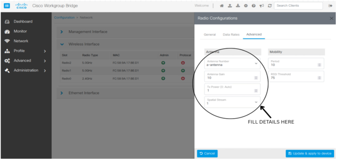
Choose Mobility and RSSI threshold to optimize wireless network performance and ensure seamless connectivity for devices.

Step 4

Select Advanced in Radio Configurations.

Step 5

Update RSSI Threshold from drop-down in Mobility.

The RSSI Threshold values are:

  • -30 dBm to -50 dBm: Excellent signal strength (ideal for most applications).

  • -50 dBm to -60 dBm: Good signal strength (suitable for reliable connectivity).

  • -60 dBm to -70 dBm: Fair signal strength (may experience minor connectivity issues).

  • -70 dBm to -80 dBm: Weak signal strength (likely to experience performance issues).

  • Less than -80 dBm: Very poor signal strength (connectivity may fail or be highly unreliable).

The default RSSI threshold value is -70 dBm.

Step 6

Modify these parameters in the Antenna drop-down to optimize signal strength, quality, coverage, and performance in wireless networks:

  • Antenna Number: optimizes signal reception and coverage.

  • Antenna Gain: measured in dBi, indicates an antenna's ability to focus signals, with higher values signifying stronger, more directional transmission.

    in Antenna Gain field, you can:

    • Enter a value

    • Use the in-field arrows to select a value.

    Values range from 2 dBi to 12 dBi.

  • Tx Power: maintains signal quality without interference.

    Values range from 1 dBm to 30 dBm.

  • Spatial Stream: Improves throughput and performance.

    Values range from 1 to 8.


Create Network Address Translation rules

You can use Network Address Translation (NAT) rules to convert private IP addresses into a single public IP address, allowing multiple devices on your network to share one public IP for internet access. This helps conserve public IP addresses and improves security by hiding internal IPs from external networks.

NAT also lets you set rules to control and manage traffic, guaranteeing only authorized data flows between your private and public networks, making it an essential tool for efficient and secure network management.

Perform these steps to create NAT rules.

Procedure


Step 1

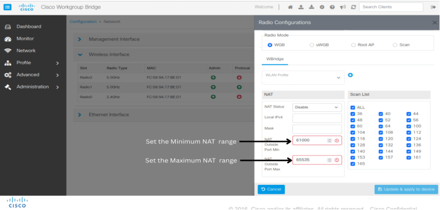
From Network page, choose the desired uplink radio in Wireless Interface.

Step 2

Set the NAT Outside Port Min and NAT Outside Port Max in Radio Configurations > NAT.

Both NAT Outside Port Min and NAT Outside Port Max values for NAT port ranges fall within the range of 1 to 65535.

Step 3

From Cisco WGB Web UI, choose Advance > NAT.

Step 4

Click Create and update these values:

  • Global port: Specify the external (public-facing) port as 443 for communication.

  • Local IP: Specify the internal (private) IP address as of the device being mapped.

  • Local Port: Specify the internal (private) port used for communication.

  • Traffic Type: Specify the type of traffic (Example: TCP, UDP) to be translated.

Step 5

Click Add & Save.


Manage firmware images

You can manage administrative tasks like reloading images, activating backups, performing factory resets, upgrading firmware, and importing or exporting configurations to efficiently maintain and update device operations.

Reload image

You can reload the currently running firmware image to apply changes or address potential software issues.

Perform these steps to reload the currently running firmware image.

Procedure


Step 1

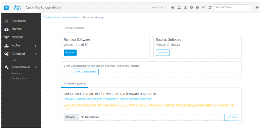
Choose Administration > Firmware.

Step 2

Click Reboot in Running Software.


Load backup image

You can load a backup image to restore the device to a previous stable state or recover from firmware-related issues.

Perform these steps to load the back up firmware image.

Procedure


Step 1

Choose Administration > Firmware.

Step 2

Click Activate in Backup Software.


Factory reset

You can perform a factory reset to restore the device to its default settings, clearing all configurations and customizations.

Perform these steps to factory reset the device.

Procedure


Step 1

Choose Administration > Firmware.

Step 2

Click Clear Configuration.

Note


After selecting Clear Configuration, the WGB goes to Day 0 scenario.


Upgrade image

You can upgrade the firmware image to access new features, enhancements, or bug fixes for improved device performance.

Perform these steps to upgrade the currently running firmware image.

Procedure


Step 1

Choose Administration > Firmware > Browse.

Step 2

Select the required image.

Step 3

Click Upgrade and wait for 180 seconds for the image to reboot and open the Web UI.


Import or export a configuration file

You can import or export configuration file to back up current settings or restore them when needed.

Perform these steps to import or export a configuration file.

Procedure


Step 1

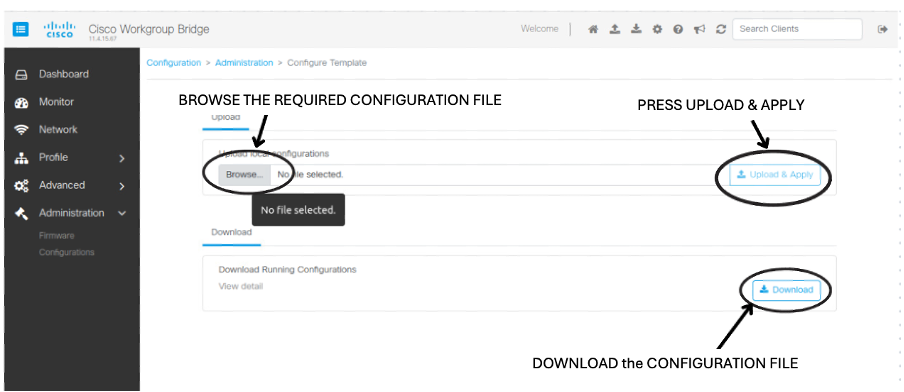
Choose Administration > Configurations.

Step 2

Click View detail to check the current configurations in Cisco WGB.

Step 3

Click Download to download the configuration.

Step 4

Upload the desired configuration to import it later when needed.

Step 5

Click Upload & Apply.

Note


The desired configuration file must be of .txt format only.

During the download, the configuration is saved to the browser.