Workgroup Bridge

Workgroup Bridge

A Workgroup Bridge (WGB) is a feature in wireless networking that allows a wired device or a group of wired devices to connect to a wireless network. Both Workgroup Bridge (WGB) and Universal Workgroup Bridge (uWGB) modes are part of WGB and that enable seamless connectivity between wired and wireless networks. From Unified Industrial Wireless (UIW) Release 17.13.1, both of these modes are supported on the Cisco Catalyst IW9165E Rugged Access Point (AP) and wireless client.

WGB mode

WGB mode provides wireless connectivity to wired clients connected to the Ethernet port of the WGB.

Key characteristics

  • Bridges the wired network to a wireless segment.

  • Learns the MAC addresses of connected Ethernet-wired clients and shares these identifiers with the Controller. This is done through an AP infrastructure using Internet Access Point Protocol (IAPP) messaging.

  • Establishes a single wireless connection to the root AP, which treats the WGB as a wireless client.


Note


This mode is ideal for environments requiring wireless connectivity for wired devices that lack native wireless capabilities.


Use case of WGB mode

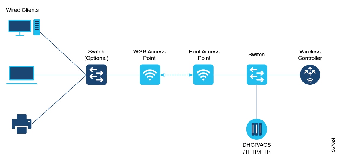
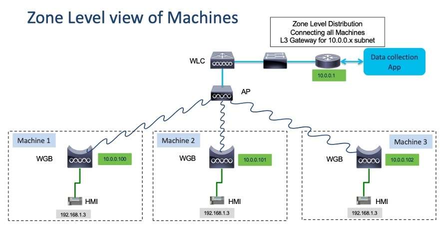
A factory floor uses wired devices such as sensors and PLCs, which lack built-in wireless connectivity. These devices connect to the WGB using Ethernet, and it bridges them to the wireless infrastructure through a single connection to the root AP.
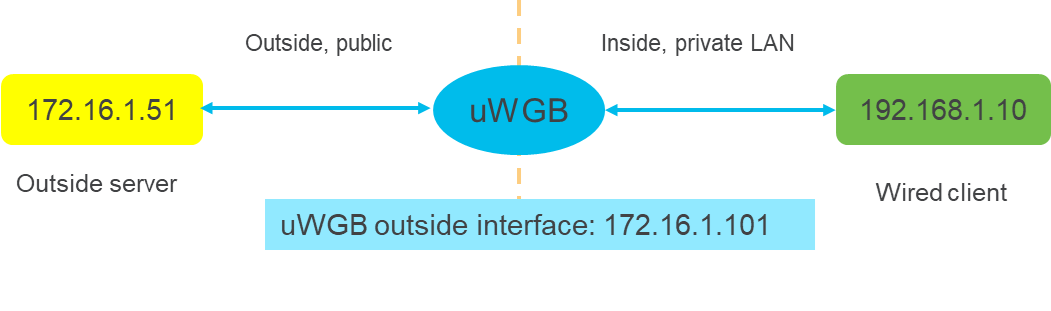
Figure 1. WGB mode implementation

uWGB mode

uWGB mode is a complementary category to the WGB mode, designed to act as a wireless bridge between wired clients and wireless infrastructure.

Key characteristics

  • Supports both Cisco and non-Cisco wireless networks.

  • Uses a wireless interface to connect with the AP, employing the radio MAC address for association.

  • Ensures that wired clients connected to the uWGB can access wireless networks seamlessly.


Note


This mode is especially useful in scenarios where interoperability with non-Cisco wireless infrastructure is required.


Comparison of key features of WGB and uWGB modes

This table outlines the differences between these two modes.

Feature

WGB mode

uWGB mode

Connectivity

Cisco wireless networks only

Cisco and non-Cisco wireless networks

Interface usage

Learns MAC addresses using Ethernet ports

Uses radio MAC address for association

Use case of uWGB mode

A retail store employs a point-of-sale (POS) system with wired devices that require connectivity to a wireless network. uWGB connects these devices to the store's wireless infrastructure, supporting both Cisco and non-Cisco wireless networks. The uWGB uses its wireless interface to associate with the AP, enabling seamless communication between the wired POS devices and the wireless network.

Use both of these modes to efficiently extend wireless capabilities to wired devices to enhance both network scalability and flexibility.

WGB mode recommendations

Understand the limitations and restrictions of both WGB and uWGB modes to ensure optimal performance and avoid potential network issues.

  • The WGB can associate only with Cisco lightweight APs.

  • Speed and duplex settings are automatically negotiated based on the locally connected endpoint's capabilities. These settings cannot be manually configured on the AP’s wired 0 and wired 1 interfaces.

  • Spanning Tree Protocol (STP) and Per-VLAN Spanning Tree (PVST) packets must be used to detect and prevent loops in wired and wireless networks. The WGB transparently bridges STP packets between two wired segments. However, incorrect or inconsistent STP configuration can cause issues such as:

    • Blocking of the WGB's wireless link to the AP or WGB by connected switches.

    • Loss of connection between the WGB and the AP or between the AP and its controller.

    • Wired clients being unable to obtain IP addresses due to blocked switch ports. To avoid these issues, disable STP on switches directly connected to the wireless network if you need to stop STP bridging by the WGB.

  • When the WGB roams to a foreign controller, a wired client can connect to the WGB network. In this case, the anchor controller shows the wired client’s IP address, but the foreign controller does not.

  • Deauthenticating a WGB record from a controller clears all entries of wired clients connected to that WGB.

  • Wired clients connected to a WGB do not support:

    • MAC filtering,

    • link tests,

    • idle timeout, and

    • web authentication.

  • A WGB cannot associate with a WLAN configured with adaptive 802.11r.

IPv6 and IPv4 support

  • The WGB supports IPv6 traffic exclusively for wired clients, even though IPv4 is enabled.

  • IPv6 management for the WGB does not function properly, even if the WGB successfully associates with an uplink. IPv6 pings and SSH to the WGB management IPv6 address do not work.


Note


Re-enable IPv6 on the WGB, even if it is already enabled and an IPv6 address has been assigned.


Channel bandwidth issue

If the infrastructure AP operates on a non-dynamic frequency selection (non-DFS) channel and changes its channel bandwidth, the WGB continues to use the original channel bandwidth.


Note


Confirm that the WGB connects to the AP using the correct channel bandwidth.


uWGB mode recommendations

  • TFTP and SFTP are not supported in uWGB mode. Perform software upgrades in WGB mode only. For more information, see uWGB Image Upgrade.

  • uWGB mode supports wired clients connected to the wired0 interface. However, it doesn't support wired clients connected to the wired1 interface.

  • You should configure an arbitrary non-routable IP address for uWGB. Using a static or dynamic IP address in the same range as the end device can result in unexpected behavior.

  • From UIW Release 17.13.1, an AP in uWGB mode is managed using SSH. Image upgrade can be performed when no wired clients are connected to the AP.

    • When a wired client is detected, the AP in uWGB mode remains in the same uWGB mode. You cannot upgrade the image of the AP.

    • When a wired client is not detected, the AP in uWGB mode switches to WGB mode. You can manage as well as upgrade the image of the AP.

Guidelines to reset the login credentials

Credential requirements

Reset your login credentials in day 0 to ensure the security of your network device. Follow these guidelines to configure new login credentials after the first login.

Table 1. Username and password recommendations

Rule type

Details

Username length

must be between 1 and 32 characters

Password length

must be between 8 and 120 characters

Password must include

  • at least one uppercase character

  • one lowercase character

  • one digit, and

  • one punctuation mark.

Password can include

  • alphanumeric characters, and

  • special characters (ASCII decimal code from 33 to 126).

Password must exclude

  • " (double quote),

  • ' (single quote), and

  • ? (question mark).

Password cannot

  • contain three consecutive characters in sequence (ABC/ CBA),

  • contain three consecutive identical characters (AAA), and

  • be the same as or the reverse of the username.

Password must contain

A new password that must have at least four characters different from the current password.

Default example credentials:

  • username: Cisco

  • password: Cisco

  • enable password: Cisco

Credentials example:

  • username: demouser

  • password: DemoP@ssw0rd

  • enable password: DemoE^aP@ssw0rd

User Access Verification
            Username: Cisco
            Password: Cisco
            
            % First Login: Please Reset Credentials
            
            Current Password:Cisco
            Current Enable Password:Cisco
            New User Name:demouser
            New Password:DemoP@ssw0rd
            Confirm New Password:DemoP@ssw0rd
            New Enable Password:DemoE^aP@ssw0rd
            Confirm New Enable Password:DemoE^aP@ssw0rd
            
            % Credentials changed, please re-login
            
            [*04/18/2023 23:53:44.8926] chpasswd: password for user changed
            [*04/18/2023 23:53:44.9074]
            [*04/18/2023 23:53:44.9074] Management user configuration saved successfully
            [*04/18/2023 23:53:44.9074]
            
            
            User Access Verification
            Username: demouser
            Password: DemoP@ssw0rd
            APFC58.9A15.C808>enable
            Password:DemoE^aP@ssw0rd
            APFC58.9A15.C808#

Note


In the provided example, passwords are displayed in plain text for clarity. In real-world scenarios, passwords are masked with asterisks (*).


Configure WLAN policy profile and VLAN settings for WGB support

Before you begin

To enable WGB to join a wireless network, you must configure the WLAN and its associated policy profile on the controller. This ensures proper communication and connectivity between the WGB and the AP.

Procedure


Step 1

Use the wlan profile-name command to enter the WLAN configuration submode.

Device#wlan profile-name

Note


Here, profile-name refers to the name of the configured WLAN.

Step 2

Use the ccx aironet-iesupport command to configure the Cisco Client Extensions (CCX) option and enable support for Aironet Information Element (IE) on the WLAN.

Device#ccx aironet-iesupport

Note


This configuration is mandatory for the WGB to associate with the AP.


Configure WLAN policy profile for WGB

Before you begin

Perform this task to configure WLAN policy profile and enable VLAN client support for a WGB on the AP. This ensures seamless client connectivity and proper VLAN assignment for WGBs in the network.

Procedure


Step 1

Use the wireless profile policy profile-policy command to access the wireless policy configuration mode for the desired profile.

Device#wireless profile policy profile-policy 

Step 2

Use the vlan vlan-id command to map the WLAN policy profile to the corresponding VLAN ID.

Device#vlan vlan-id 

Step 3

Use the wgb vlan command to enable VLAN client support for the WGB.

Device#wgb vlan 

Condition

Action or result

If the profile-policy does not exist

Create the wireless profile policy before proceeding with the configuration.

If the VLAN ID is not correctly assigned

Reassign the VLAN using the correct vlan-id to ensure proper connectivity.

If WGB VLAN support is not enabled

Execute the wgb vlan command to allow client support for WGBs.


What to do next


Note


  • Ensure that you have administrative access to the device before configuring.

  • Verify that the VLAN ID you assign exists and is configured on the network infrastructure.


Upgrade the uWGB image

Before you begin

The uWGB mode does not support TFTP or SFTP protocols for image upgrades. Therefore, the device must first be converted to WGB mode to enable the image upgrade process.

Procedure


Step 1

Connect a TFTP or SFTP server to the wired 0 port of the uWGB.

Step 2

Use the configure Dot11Radio slot_id disable command to disable the radio interface.

Device#configure Dot11Radio slot_id disable 

Step 3

Use the configure Dot11Radio slot_id mode wgb ssid-profile ssid_profile_name command to configure the device to WGB mode using an existing SSID profile.

Device#configure Dot11Radio slot_id mode wgb ssid-profile ssid_profile_name 

This command will reboot with downloaded configs.
Are you sure you want continue? <confirm>

Note

 
  • Replace ssid_profile_name with any existing configured SSID profile.

  • This command reboots the device with the downloaded configuration

Step 4

Use the configure ap address ipv4 static IPv4_address netmask Gateway_IPv4_address command to assign a static IP address to the device.

Device#configure ap address ipv4 static 192.168.1.101 255.255.255.0 192.168.1.1

Step 5

Use the pingserver_IP command to test ICMP connectivity to the server.

Device#ping server_IP

Example:

Device#ping 192.168.1.20
Sending 5, 100-byte ICMP Echos to 192.168.1.20, timeout is 2 seconds

PING 192.168.1.20
!!!!!
Success rate is 100 percent (5/5), round-trip min/avg/max = 0.858/0.932/1.001 ms

Step 6

Use the archive download/reload <tftp | sftp | http >://server_ip /file_path command to download andupgrade the uWGB image using TFTP, SFTP, or HTTP.

Device#archive download/reload <tftp | sftp | http >://server_ip /file_path 

Step 7

Use the configure Dot11Radio slot_id mode uwgb wired_client_mac_addr ssid-profile ssid_profile_name command to switch the device back to uWGB mode.

Device#configure Dot11Radio slot_id mode uwgb wired_client_mac_addr ssid-profile ssid_profile_name

Know your AP status using LED indicators

LED patterns are indicator light sequences that display the operational status and signal strength of a device.

These patterns use visual cues, such as blinking or solid lights, to convey specific conditions or performance metrics. In the context of the IW9165E device, LED patterns help identify system status and signal quality.

IW9165E LED Indicators

The IW9165E device features two LEDs located on the front panel:

  1. System Status LED

  2. RSSI Status LED

Table 2. Visual Reference: LED Status Indicators

LED

Color or Pattern

Indication

System Status LED

Blinking Red

WGB is disassociated.

Solid Green

WGB is associated with the parent AP.

RSSI Status LED

Solid Green

RSSI ≥ -71 dBm.

Blinking Green

RSSI between -81 dBm and -70 dBm.

Solid Yellow

RSSI between -95 dBm and -81 dBm.

Off

RSSI outside specified ranges.

Configure IP address

Configure an IPv4 address

The purpose of this task is to configure an IPv4 address on a device using either the DHCP or a static configuration. This task ensures proper network connectivity and device management.

Procedure


Step 1

Use the configure ap address ipv4 dhcp command to dynamically assign an IPv4 address using DHCP.

Device#configure ap address ipv4 dhcp 

Step 2

Use the configure ap addressipv4 staticipv4_addr netmask gateway command to manually assign a static IPv4 address on the device.

Device#configure ap address ipv4 static ipv4_addr netmask gateway

Note

 
  • By configuring a static address, you can manage the device through a wired interface, even if an uplink connection is unavailable.

  • For static configuration, ensure that the IPv4 address, netmask, and gateway parameters should align with your network requirements to avoid connectivity issues.


Verify the current IPv4 configuration

Perform this task is to verify the current IP address configuration on your device to have accurate network setup and troubleshooting.

Procedure


Use the show ip interface brief command to to view the current IP address configuration.

Device#show ip interface brief

Configure IPv6 address

Perform this task to configure a static IPv6 address for the device. Configuring a static IPv6 address allows you to manage the AP through a wired interface, even if there is no uplink connection.

Procedure


Use the configure ap address ipv6 static ipv6_addr prefixlen [gateway] command to configure the static IPv6 address.

Device#configure ap address ipv6 static ipv6_addr prefixlen [gateway]

Important


This configuration allows you to manage the AP through a wired interface without uplink connection.


Enable IPv6 auto-configuration on the AP

Before you begin

Enable the AP to automatically configure its IPv6 address, ensuring efficient network management and reducing manual configuration tasks.

Procedure


Use the configure ap address ipv6 auto-config enable command to enable the IPv6 auto configuration on the AP.

Note

 
  • Use the configure ap address ipv6 auto-config disable command to disable the IPv6 auto configuration on the AP.

  • Enabling IPv6 auto-configuration also activates Stateless Address Auto-Configuration (SLAAC), but SLAAC does not apply to CoS of WGB. This command configures IPv6 address using DHCPv6 instead of SLAAC.


Configure IPv6 address using DHCP

Before you begin

Perform this task to configure an IPv6 address on a device using DHCP. This procedure ensures that the device automatically obtains an IPv6 address from a DHCP server.

Procedure


Use the configure ap address ipv6 dhcp command to configure IPv6 address using DHCP.

Device#configure ap address ipv6 dhcp

Condition

Action or Result

The DHCP server is reachable

The device successfully obtains an IPv6 address.

The DHCP server is not reachable The device fails to acquire an IPv6 address. Check network connectivity.

No DHCP server is configured

No IPv6 address is assigned. Configure a DHCP server or use static addressing.


Verify current IPv6 configuration

Before you begin

Perform this task to verify the IPv6 interface configuration on a device, which is essential for diagnosing network connectivity problems or confirming interface settings.

Procedure


Use the show ipv6 interface brief command to verify current IP address configuration.

Device#show ipv6 interface brief

Configure WGB on the radio interface

Perform these tasks to configureWGB on the radio interface:

Before you begin

WGB allows non-wireless devices to connect to a wireless network. This configuration involves creating an SSID profile, configuring the WGB on the radio interface, and associating the SSID profile with the interface.

Procedure


Step 1

Create an SSID profile.

Choose one of the following authentication methods based on your network requirements:

  • Open authentication,

  • Pre-shared Key (PSK) authentication: Supported options include WPA2, Dot11r, or Dot11w.

  • Dot1x authentication: Examples include EAP-PEAP, EAP-FAST, or EAP-TLS.

If

Then

If using Open authentication

Proceed without additional security configuration.

If using PSK authentication

Input the pre-shared key during SSID profile setup.

If using Dot1x authentication

Configure the required EAP method and credentials.

Step 2

Configure the radio interface for WGB mode. Access the radio interface settings and apply the required configuration to enable WGB functionality.

Step 3

Associate the SSID profile with the radio. Link the previously created SSID profile to the radio interface to establish the connection.

Step 4

Enable the radio interface. Activate the radio interface to complete the WGB configuration and begin operation.

These sections provide detailed information on the WGB configuration procedure.


Create an SSID profile

Before you begin

Perform this task to configure an SSID profile that meets your network's authentication requirements and ensures secure access for users.

Procedure


Select an authentication protocol for the SSID profile.

Depending on your network requirements, choose one of the following authentication protocols:

Note


For PSK configurations, ensure that the pre-shared key is strong and follows recommended security practices.

If..

Then..

If Open Authentication is selected

The network allows users to connect without credentials.

If PSK WPA2 Authentication is selected

User connects using a pre-shared key with WPA2 encryption.

If Dot1x Authentication is selected

User authenticates using a centralized server.


Configure an SSID profile using open authentication

Open authentication allows devices to connect to the network without requiring credentials, making it suitable for specific scenarios like guest networks or public access points.

Before you begin

Ensure you are in privileged EXEC mode.

Procedure

Use the configure ssid-profile ssid-profile-name ssid radio-serv-name authentication open command to configure an SSID profile using open authentication.

Device#configure ssid-profile ssid-profile-name ssid radio-serv-name authentication open 

Configure an SSID profile using PSK authentication

PSK authentication is a commonly used method to secure wireless networks by providing a shared key to users. This task provides step-by-step instructions for configuring SSID profiles with PSK authentication, tailored to various key management protocols.

Procedure

Choose an authentication protocol.

Select one of the following protocols to configure an SSID profile with PSK authentication:

  • WPA2: Provides enhanced security for wireless communication.

  • Dot11r: Enables fast roaming capabilities for mobile devices.

  • Dot11w: Protects management frames from tampering.


Configure an SSID profile using PSK WPA2 authentication

Perform this task to set up an SSID profile with PSK WPA2 authentication for secure wireless network access.

Procedure

Use the configure ssid-profile ssid-profile-name ssid SSID_name authentication psk preshared-key key-management wpa2 command to configure an SSID profile using PSK WPA2 authentication.

Device#configure ssid-profile ssid-profile-name ssid SSID_name authentication psk preshared-key key-management wpa2

Configure an SSID profile using PSK Dot11r authentication

Perform this task to configure an SSID profile with PSK (Pre-Shared Key) authentication using Dot11r key management. This ensures secure and seamless roaming for wireless clients.

Procedure

Use the configure ssid-profile ssid-profile-name ssid SSID_name authentication psk preshared-key key-management dot11r command to configure an SSID profile using PSK Dot11r authentication.

Device#configure ssid-profile ssid-profile-name ssid SSID_name authentication psk preshared-key key-management dot11r 

Configure an SSID profile using PSK Dot11w authentication

Perform this task to configure an SSID profile with PSK authentication using Dot11w key management. This ensures secure and reliable access to the wireless network.

Procedure

Use the configure ssid-profile ssid-profile-name ssid SSID_name authentication psk preshared-key key-management dot11w command to configure an SSID profile using PSK Dot11w authentication

Device#configure ssid-profile ssid-profile-name ssid SSID_name authentication psk preshared-key key-management dot11w 

Configure an SSID profile using Dot1x authentication

Dot1x authentication is a network access control method that enhances security by requiring user credentials before granting access. This task guides you in configuring the SSID profile with appropriate key management options.

Perform this task to set up an SSID profile with Dot1x authentication, ensuring secure network access using Extensible Authentication Protocol (EAP).

Procedure

Use the configure ssid-profile ssid-profile-name ssid radio-serv-name authentication eap profile eap-profile-name key-management { dot11r | wpa2 | dot11w { optional | required}} command to configure an SSID profile using Dot1x authentication.

Device#configure ssid-profile ssid-profile-name ssid radio-serv-name authentication eap profile eap-profile-name key-management { dot11r | wpa2 | dot11w { optional | required}}

If..

Then..

If you want to enable fast roaming

Use the dot11r key-management option.

If WPA2 security is required

Use the wpa2 key-management option.

If management frame protection is needed

Use the dot11w key-management option with optional or required.


Configure radio interface for WGB

IW9165E does not have 2.4 GHz radio. You can configure only dot11radio 1 as uplink and operate in WGB mode.

Use the configure dot11radio slot_id mode wgb ssid-profile ssid-profile-name command to configure a radio interface to a WGB SSID profile.
Device#configure dot11radio 1 mode wgb ssid-profile ssid-profile-name
Enable radio interface for WGB

Use the configure dot11radio slot_id enable command to enable a radio interface.

Device#configure dot11radio 1 enable

Note


Use the configure dot11radio slot_id disable command to disable a radio interface.


Configure an SSID profile using Dot1x authentication

Dot1x authentication is a network access control method that enhances security by requiring user credentials before granting access. This task guides you in configuring the SSID profile with appropriate key management options.

Perform this task to set up an SSID profile with Dot1x authentication, ensuring secure network access using Extensible Authentication Protocol (EAP).

Procedure


Use the configure ssid-profile ssid-profile-name ssid radio-serv-name authentication eap profile eap-profile-name key-management { dot11r | wpa2 | dot11w { optional | required}} command to configure an SSID profile using Dot1x authentication.

Device#configure ssid-profile ssid-profile-name ssid radio-serv-name authentication eap profile eap-profile-name key-management { dot11r | wpa2 | dot11w { optional | required}}

If..

Then..

If you want to enable fast roaming

Use the dot11r key-management option.

If WPA2 security is required

Use the wpa2 key-management option.

If management frame protection is needed

Use the dot11w key-management option with optional or required.


Configure an SSID profile using Dot1x EAP-PEAP authentication

Before you begin

Perform this task to set up a secure SSID profile using Dot1x EAP-PEAP authentication, which provides enhanced security for wireless networks.

This task is applicable when configuring wireless profiles on devices that support Dot1x EAP-PEAP authentication. This ensures the device can authenticate securely using a specified username and password.

Procedure


Step 1

Configure Dot1x credentials

Use the configure dot1x credential credential_name username username password password command to create Dot1x credentials

Device#configure dot1x credential <credential_name> username <username> password <password>

Step 2

Create an EAP profile

Use the configure eap-profile profile_name dot1x-credential credential_name command to configure the EAP profile and associate it with the configured Dot1x credentials.

Device#configure eap-profile <profile_name> dot1x-credential <credential_name>

Step 3

Specify the EAP method

Use the configure eap-profile profile_name method peap command to define the EAP method for the profile as PEAP.

Device#configure eap-profile <profile_name> method peap

Step 4

Configure the SSID profile

Use the configure ssid-profile ssid-profile-name ssid ssid name authentication eap profile eap-profile-name key-management wpa2 command to create an SSID profile and set up authentication using the EAP profile.

Device#configure ssid-profile iot-peap ssid iot-peap authentication eap profile p1 key-management wpa2

Configure radio interface for WGB mode

Configure the radio interface to enable the WGB mode and establish a connection to the appropriate SSID profile.

Before you begin

The IW9165E device does not support a 2.4 GHz radio. Therefore, only the dot11radio 1 interface can be configured as the uplink to operate in WGB mode.

Procedure


Use the configure dot11radio slot_id mode wgb ssid-profile ssid-profile-name command to configure the radio interface and associate it with a WGB SSID profile.

Device#configure dot11radio 1 mode wgb ssid-profile ssid-profile-name

Note


Ensure that the SSID profile being used is already configured and accessible by the device.


Enable or disable radio interface for WGB

Before you begin

Enable the radio interface to allow the WGB to transmit and receive wireless signals.

Procedure


Use the configure dot11radio slot_id enable command toto enable a specific radio interface.

Device# configure dot11radio 1 enable

Note


Use the configure dot11radio 1 disable command to disable the radio interface.


Configure Dot1X credential

This task ensures the device is correctly configured for 802.1X authentication, which is essential for network security and access control.

Perform this task to configure a Dot1X credential, enabling secure authentication for devices on the network.

Procedure


Use the configure dot1x credential profile-name username namepassword pwd command to configure the Dot1X credential.

Device#configure dot1x credential profile-name username name password pwd

Verify the WGB EAP Dot1x profile using CLI

Verify the status of the WGB EAP Dot1x profile to ensure the device is correctly configured for authentication.

Procedure


Use the show wgb eap dot1x credential profile command to view the status of the WGB EAP Dot1x profile.

Device#show wgb eap dot1x credential profile 

Deauthenticate WGB wired client

Use the clear wgb client {all |single mac-addr} command to deauthenticate WGB wired client.

Device#clear wgb client {all |single mac-addr} 

Configure EAP-TLS security

Perform this task to enable EAP-TLS security on the WGB. This configuration ensures secure authentication and encryption for wireless communication.

Procedure


Step 1

Set up the device parameters.

  • Configure the device username and password.

  • Configure the NTP server to ensure accurate time synchronization.

  • Define the hostname and assign a valid IP address.

Step 2

Create and import trustpoints.

Establish trustpoints and import the required certificates using your preferred method.

Step 3

(Optional) Configure the dot1x credentials.

Provide the necessary dot1x username and password credentials if required by your setup.

Step 4

Create the EAP profile.

Map the EAP method, trustpoint name, and (optionally) the dot1x credentials to the EAP profile.

Step 5

Bind the EAP profile to the SSID profile.

Associate the EAP profile with the desired SSID profile to enable secure wireless connections.

Step 6

Bind the SSID profile to the radio.

Link the SSID profile to the preferred radio interface to activate the configuration.

Note

 
  • Ensure that the NTP server is reachable and the certificates are valid to avoid authentication failures.

  • Use a secure method to import certificates to maintain system integrity.

Condition

Action/Result

If the dot1x credentials are not required,

Skip Step 3 and proceed to Step 4.

If the certificate import fails,

Verify the certificate format and re-import using a valid method.


What to do next


Note


If you make any modifications to the dot1x credential profile, trustpoint profile, or EAP profile, the changes do not take effect immediately. You must manually re-attach the EAP profile to the SSID profile for the changes to apply.

Use configure ssid-profile <ssid_prof_name> ssid authentication eap profile <eap_prof_name> key-management <key_type> command to re-attach the EAP profile to the SSID profile.
Device#configure ssid-profile <ssid_prof_name> ssid <ssid name> authentication eap profile <eap_prof_name> key-management <key_type>

Configure an EAP profile

This task guides you through the steps required to configure an Extensible Authentication Protocol (EAP) profile, ensuring secure and efficient authentication for your network.

Before you begin

An EAP profile is critical in ensuring secure authentication for wireless clients. Configuring the profile correctly ensures seamless integration with Dot1x credentials, SSID profiles, and radio configurations.

Before you begin configuring an EAP profile, ensure the following:

  1. A valid Dot1x credential profile is already created.

  2. The SSID profile has been configured.

  3. The radio to which the SSID will be attached is properly set up.

  4. Administrative access to the device's CLI.

Procedure


Step 1

Configure the EAP Profile

Use the configure eap-profile profile-name method { fast | leap | peap | tls} command to configure the EAP profile with the desired method.

Device#configure eap-profile profile-name method { fast | leap | peap | tls} 

Note


Choose an EAP profile method.

  • fast,

  • leap,

  • peap, or

  • tls.

If..

Then..

If the TLS method is selected for the EAP profile

Attach a CA trustpoint using Step 2.

If a profile is no longer needed

Use Step 4 to delete the EAP profile.

Step 2

Attach the CA Trustpoint for TLS

Use the configure eap-profile profile-name trustpoint { default | name trustpoint-name} command to attach the CA trustpoint for TLS. By default, the WGB uses the internal MIC certificate for authentication.

Device#configure eap-profile profile-name trustpoint { default | name trustpoint-name} 

Step 3

Attach the Dot1x Credential Profile

Use the configure eap-profile profile-name dot1x-credential profile-name command to attach the dot1x-credential profile.

Device#configure eap-profile profile-name dot1x-credential profile-name 

Step 4

(Optional) Delete an EAP Profile

[Optional] Use the configure eap-profile profile-name delete command to delete an EAP profile.

Device#configure eap-profile profile-name delete 

Example:

Dot1x FAST-EAP configuration example

configure dot1x credential demo-cred username demouser1 password Dem0Pass!@
configure eap-profile demo-eap-profile dot1x-credential demo-cred
configure eap-profile demo-eap-profile method fast
configure ssid-profile demo-FAST ssid demo-fast authentication eap profile demo-eap-profile key-management wpa2
configure dot11radio 1 mode wgb ssid-profile demo-FAST
configure dot11radio 1 enable

Configure trustpoint manual enrollment for terminal

This procedure explains how to manually configure a trustpoint for terminal-based enrollment. It ensures secure communication between the device and the Certificate Authority (CA) server by enabling the use of a trusted certificate.

Procedure


Step 1

Create a Trustpoint in WGB.

Use the configure crypto pki trustpoint ca-server-name enrollment terminal command to create a trustpoint in WGB.

Device#configure crypto pki trustpoint ca-server-name enrollment terminal 

Step 2

Authenticate the Trustpoint Manually.

Use the configure crypto pki trustpoint ca-server-name authenticate command to authenticate the trustpoint manually.

Enter the base 64 encoded CA certificate.

Enter quit to finish the certificate.

Note


If you use an intermediate certificate, import all the certificate chains in the trustpoint.

Example:

Device#configure crypto pki trustpoint demotp authenticate
 
Enter the base 64 encoded CA certificate.
....And end with the word "quit" on a line by itself....
 
-----BEGIN CERTIFICATE-----
[base64 encoded root CA certificate]
-----END CERTIFICATE-----
-----BEGIN CERTIFICATE-----
[base64 encoded intermediate CA certificate]
-----END CERTIFICATE-----
quit

Note


If an intermediate certificate is used, import all certificate chains in the trustpoint.

Step 3

Configure the Private Key Size.

Use the configure crypto pki trustpoint ca-server-name key-size key-length command to configure a private key size.

Device#configure crypto pki trustpoint ca-server-name key-size key-length 

Step 4

Configure the subject name.

Use the configure crypto pki trustpoint ca-server-name subject-name name [Optional] 2ltr-country-code state-name locality org-name org-unit email command to configure the subject-name.

Device#configure crypto pki trustpoint ca-server-name subject-name name [Optional] 2ltr-country-code state-name locality org-name org-unit email 

Step 5

Generate a private key and certificate signing request (CSR).

Use the configure crypto pki trustpoint ca-server-name enroll command to generate a private key and CSR.

Device#configure crypto pki trustpoint ca-server-name enroll 

Note


Use the CSR output to create a digitally signed certificate on the CA server.

Step 6

Import the signed certificate.

Use the configure crypto pki trustpoint ca-server-name import certificate command to import the signed certificate in WGB.

Device#configure crypto pki trustpoint ca-server-name import certificate 

Enter the base64-encoded CA certificate and type quit to finish importing the certificate.

Device#quit 

Step 7

(Optional) Delete a Trustpoint.

(Optional) Use the configure crypto pki trustpoint trustpoint-name delete command to delete a trustpoint.

Device#configure crypto pki trustpoint trustpoint-name delete 

Verify trustpoint summary

Understand the configuration and status of all trustpoints on the device to verify secure communication settings and troubleshoot issues, if necessary.

Procedure


Use the show crypto pki trustpoint command to display a summary of all trustpoints.

Device#show crypto pki trustpoint

Verify trustpoint certificates

Perform this task to retrieve and view the details of certificates created for a specific trustpoint. This task helps validate the configuration and confirm the certificate's properties for troubleshooting or verification purposes.

Procedure


Use the show crypto pki trustpoint trustpoint-name certificate command to view the content of the certificates that are created for a trustpoint.

Device# show crypto pki trustpoint trustpoint-name certificate  

Configure trustpoint auto-enrollment for WGB

Perform this task to configure auto-enrollment for trustpoints on a WGB, ensuring secure certificate management and streamlined operations.

Procedure


Step 1

Enroll a trustpoint using the server URL.

Use the configure crypto pki trustpoint ca-server-name enrollment url ca-server-url command to enroll a trustpoint in the WGB using the server URL.

Device#configure crypto pki trustpoint ca-server-name enrollment url ca-server-url 

Step 2

Authenticate the trustpoint.

Use the configure crypto pki trustpoint ca-server-name authenticate command to authenticate a trustpoint.

Device#configure crypto pki trustpoint ca-server-name authenticate 

Note


This command automatically fetches the Certificate Authority (CA) certificate from the CA server.

Step 3

Configure the private key size.

Use the configure crypto pki trustpoint ca-server-name key-size key-length command to configure a private key size.

Device#configure crypto pki trustpoint ca-server-name key-size key-length 

Step 4

Configure the subject name.

Use the configure crypto pki trustpoint ca-server-name subject-name name [Optional] 2ltr-country-code state-name locality org-name org-unit email command to configure the subject-name.

Device#configure crypto pki trustpoint ca-server-name subject-name name [Optional] 2ltr-country-code state-name locality org-name org-unit email 

Step 5

Enroll the trustpoint.

Use the configure crypto pki trustpoint ca-server-name enroll command to enroll the trustpoint.

Device#configure crypto pki trustpoint ca-server-name enroll 

Note


This step requests a digitally signed certificate from the CA server.

Step 6

Enable auto-enrollment.

Use the configure crypto pki trustpoint ca-server-name auto-enroll enable renew-percentage command to enable auto-enroll.

Device#configure crypto pki trustpoint ca-server-name auto-enroll enable renew-percentage 

Note


Use the configure crypto pki trustpoint ca-server-name auto-enroll disable command to disable the auto-enroll.

Step 7

(Optional) Delete a trustpoint.

(Optional) Use the configure crypto pki trustpoint trustpoint-name delete command to delete a trustpoint.

Device#configure crypto pki trustpoint trustpoint-name delete 

Step 8

To verify the trustpoint summary, see Verify trustpoint summary.

Step 9

To verify the details of the certificate for a specific trustpoint, see Verify trustpoint certificates.


Verify the PKI timer information

Procedure


Use the show crypto pki timers command to view the public key infrastructure (PKI) timer information.

Device#show crypto pki timers 

Configure manual certificate enrollment using a TFTP server

Perform this task to manually enroll certificates using a TFTP server. This ensures secure communication by retrieving, authenticating, and managing certificates for a trustpoint.

Procedure


Step 1

Specify the enrollment method.

Use the configure crypto pki trustpoint ca-server-name enrollment tftp tftp-addr/file-name command to retrieve the CA and client certificate for a trustpoint.

Device#configure crypto pki trustpoint ca-server-name enrollment tftp tftp-addr/file-name 

Step 2

Authenticate the trustpoint manually.

Use the configure crypto pki trustpoint ca-server-name authenticate command to retrieve and authenticate the CA certificate from the specified TFTP server.

Device#configure crypto pki trustpoint ca-server-name authenticate 

Note


This retrieves and authenticates the CA certificate from the specified TFTP server. If the file specification is included, the WGB adds the extension .ca to the specified filename.

Step 3

Configure the private key size.

Use the configure crypto pki trustpoint ca-server-name key-size key-length command to configure a private key size.

Device#configure crypto pki trustpoint ca-server-name key-size key-length 

Step 4

Configure the subject name.

Use the configure crypto pki trustpoint ca-server-name subject-name name [Optional] 2ltr-country-code state-name locality org-name org-unit email command to configure the subject name for the trustpoint.

Device#configure crypto pki trustpoint ca-server-name subject-name name [Optional] 2ltr-country-code state-name locality org-name org-unit email 

Step 5

Generate the private key and Certificate Signing Request (CSR).

Use the configure crypto pki trustpoint ca-server-name enroll command to generate a private key and CSR, and send the request to the TFTP server.

Device#configure crypto pki trustpoint ca-server-name enroll 

Note


This generates certificate request and sends the request to the TFTP server. The filename to be written is appended with the .req extension.

Step 6

Import the signed certificate.

Use the configure crypto pki trustpoint ca-server-name import certificate command to import the signed certificate into the WGB.

Device#configure crypto pki trustpoint ca-server-name import certificate

The console terminal uses TFTP to import a certificate and the WGB tries to get the approved certificate from the TFTP. The filename to be written is appended with the .crt extension.

Step 7

To verify the trustpoint summary, see Verify trustpoint summary.

Step 8

To verify the details of the certificate for a specific trustpoint, see Verify trustpoint certificates.


Configure a PKCS12 or PFX or P12 certificate enrollment using a TFTP server

This task enables you to import a PKCS12 full certificate bundle for EAP-TLS authentication and private key configuration. This ensures secure communication and device authentication in WGB mode.

Procedure


Import the PKCS12 certificate bundle.

Use configure crypto pki trustpoint trustpoint_name import pkcs12 tftp tftp://IP_ADDRESS/path_to_certificate password certificate_password command to import PKCS12 full certificate bundle for EAP-TLS authentication and private key.

Device#configure crypto pki trustpoint trustpoint1 import pkcs12 tftp tftp://1.2.3.4/cert.crt

Verify PKCS12 or PFX or P12 certificate enrollment for WGB mode

Procedure

Perform this task to ensure that the PKCS12 certificate is successfully downloaded and properly enrolled for WGB mode.


Perform this task to ensure that the PKCS12 certificate is successfully downloaded and properly enrolled for WGB mode.

Use the show crypto pki trustpoint command to verify the downloaded PKCS12 certificate.

Example:

Device#show crypto pki trustpoint
Crypto PKI trustpoints are:-
================================================================
     Trustpoint name : example
   Enrollment method : TFTP
           TFTP path : tftp://192.168.0.1/users/example/ca
        CA-Cert file : /storage/wbridge_pki_cert/example/example_ca.pem
             Subject : C=US,ST=Unknown,L=Unknown,O=Cisco,OU=Wnbu,CN=ap.cisco.com
,emailAddress=wgb@cisco.com
            Key size : 2048 

Configure WGB or uWGB timer

Configure timers for the WGB or uWGB modes to ensure proper timeout settings for association, authentication, EAP, and bridge client responses. The CLI commands for timer configuration are identical for both the WGB and uWGB modes.

Configure the WGB association response timeout

Procedure

Use the configure wgb association response timeout response-millisecs command to configure the WGB association response timeout.

Device#configure wgb association response timeout response-millisecs 

Note

 
  • Default Value: 100 milliseconds

  • Valid Range: 100–5000 milliseconds


Configure the WGB authentication response timeout

Procedure

Use the configure wgb authentication response timeout response-millisecs command to configure the WGB authentication response timeout.

Device#configure wgb authentication response timeout response-millisecs 
  • Default Value: 100 milliseconds

  • Valid Range: 100 –5000 milliseconds


Configure the WGB EAP timeout

Procedure

Use the configure wgb eap timeout timeout-secs command to configure the WGB EAP timeout.

Device#configure wgb eap timeout timeout-secs 
  • Default value: 3 seconds

  • Valid range: 2–60 seconds


Configure the WGB bridge client response timeout

Procedure

Use the configure wgb bridge client timeout timeout-secs command to configure the WGB bridge client response timeout.

Device#configure wgb bridge client timeout timeout-secs 
  • Default Value: 300 seconds

  • Valid Range: 10–1,000,000 seconds


Configure uWGB on the radio interface

The uWGB mode can associate with third-party APs using uplink radio MAC address, thus the uWGB role supports only one wired client.

Most WGB configurations also apply to uWGB mode. The only difference is that you configure wired client’s MAC address using this command:

Procedure


Step 1

Configure the wired client's MAC address in uWGB mode.

Use Device#configure dot11 <slot_id > mode uwgb <uwgb_wired_client_mac_address > ssid-profile <ssid-profile > command to configure the wired client's MAC address.

evice#configure dot11 <slot_id> mode uwgb <uwgb_wired_client_mac_address> ssid-profile <ssid-profile>

Step 2

Device#configure dot11 <slot_id > mode uwgb <uwgb_wired_client_mac_address > ssid-profile <ssid-profile >

Dot1x FAST-EAP configuration example:

Device#configure dot1x credential demo-cred username demouser1 password Dem0Pass!@
Device#configure eap-profile demo-eap-profile dot1x-credential demo-cred
Device#configure eap-profile demo-eap-profile method fastDevice#
Device#configure ssid-profile demo-FAST ssid demo-fast authentication eap profile demo-eap-profile key-management wpa2
Device#configure dot11radio 1 mode uwgb fc58.220a.0704 ssid-profile demo-FAST
Device#configure dot11radio 1 enable

These configurations outlines the detailed information about uWGB setup and common for both WGB and uWGB:


Conversion between WGB and uWGB modes

Conversion from WGB to uWGB mode

Perform this task to convert the device from WGB to uWGB mode. This conversion enables enhanced functionality and integration of wired clients with the desired SSID profile.

Procedure


Use the configure dot11radio <radio_slot_id > mode uwgb <WIRED_CLIENT_MAC > ssid-profile <SSID_PROFILE_NAME > command to convert from WGB to uWGB mode.

Device#configure dot11radio <radio_slot_id> mode uwgb <WIRED_CLIENT_MAC> ssid-profile <SSID_PROFILE_NAME>

Conversion from uWGB to WGB mode

Perform this task to convert an AP from uWGB mode to WGB mode, enabling it to function in WGB mode.

Procedure


Step 1

Use the configure dot11radio <radio_slot_id > mode wgb ssid-profile <SSID_PROFILE_NAME > command to convert from uWGB to WGB mode. This conversion involves rebooting of the AP.

Device#configure dot11radio 1 mode wgb ssid-profile <SSID_PROFILE_NAME>

 This command will reboot with downloaded configs.
 Are you sure you want continue? [confirm]

Step 2

After entering the command, the system prompts you to confirm the action. This step is necessary as the AP reboots to apply the new configuration.

When prompted, type confirm to proceed with the conversion.


Import and export WGB configuration

Import a WGB configuration

Perform this task to download a sample configuration file to all WGBs in the deployment. This ensures the devices are configured with the necessary settings for proper operation.

Procedure


Use the copy configuration download <sftp:|tftp:> ip-address [directory] [file-name] command to download a sample configuration to all WGBs in the deployment.

Device#copy configuration download <sftp:|tftp:> ip-address [directory] [file-name]

Note

 
  • When you execute the copy configuration download command, the AP starts to reboot. The new configuration takes effect only after the reboot.

  • Ensure that the configuration file is accessible from the specified sftp: or tftp: server and that the file path is correctly specified.


Export WGB configuration

Export the configuration of an existing WGB to make it reusable for newly deployed WGBs. This ensures consistency and simplifies deployment.

You can upload the current configuration of a WGB to a server using the appropriate protocol (SFTP or TFTP). This configuration file can later be downloaded to configure additional WGBs, streamlining the setup process.

Procedure


Upload the WGB configuration to a server

Use the copy configuration upload <sftp:|tftp:> ip-address [directory] [file-name] command to upload the working configuration of an existing WGB to a server.

Device#copy configuration upload <sftp:|tftp:> ip-address [directory] [file-name]

Verify the WGB and uWGB configuration

Perform these tasks to verify WGB and uWGB related show configurations.

Procedure


Step 1

Use the show run command to check whether the AP is in WGB or uWGB mode.

  • WGB:

    Device#show run
    AP Name              : APFC58.9A15.C808
    AP Mode              : WorkGroupBridge
    CDP State            : Enabled
    Watchdog monitoring  : Enabled
    SSH State            : Disabled
    AP Username          : admin
    Session Timeout      : 300
     
     
    Radio and WLAN-Profile mapping:-
    ====================================
    Radio ID    Radio Mode    SSID-Profile                    SSID
              Authentication
    --------------------------------------------------------------------------------
    --------------------------
    1           WGB           myssid                          demo
              OPEN
     
     
    Radio configurations:-
    ===============================
    Radio Id             : NA
       Admin state       : NA
       Mode              : NA
    Radio Id             : 1
       Admin state       : DISABLED
       Mode              : WGB
       Dot11 type        : 11ax
    Radio Id             : NA
       Admin state       : NA
       Mode              : NA
     
  • uWGB:

    Device#show run
    AP Name              : APFC58.9A15.C808
    AP Mode              : WorkGroupBridge
    CDP State            : Enabled
    Watchdog monitoring  : Enabled
    SSH State            : Disabled
    AP Username          : admin
    Session Timeout      : 300
     
     
    Radio and WLAN-Profile mapping:-
    ====================================
    Radio ID    Radio Mode    SSID-Profile                    SSID
              Authentication
    --------------------------------------------------------------------------------
    --------------------------
    1           UWGB          myssid                          demo
              OPEN
     
     
    Radio configurations:-
    ===============================
    Radio Id             : NA
       Admin state       : NA
       Mode              : NA
    Radio Id             : 1
       Admin state       : DISABLED
       Mode              : UWGB
       Uclient mac       : 0009.0001.0001
       Current state     : WGB
       UClient timeout   : 0 Sec
       Dot11 type        : 11ax
    Radio Id             : NA
       Admin state       : NA
       Mode              : NA
    

Step 2

Use the show wgb dot11 associations command to view the WGB and uWGB configuration.

  • WGB:

    Device#show wgb dot11 associations
    Uplink Radio ID : 1
    Uplink Radio MAC : 00:99:9A:15:B4:91
    SSID Name : roam-m44-open
    Parent AP Name : APFC58.9A15.C964
    Parent AP MAC : 00:99:9A:15:DE:4C
    Uplink State : CONNECTED
    Auth Type : OPEN
    Dot11 type : 11ax
    Channel : 100
    Bandwidth : 20 MHz
    Current Datarate (Tx/Rx) : 86/86 Mbps
    Max Datarate : 143 Mbps
    RSSI : 53
    IP : 192.168.1.101/24
    Default Gateway : 192.168.1.1
    IPV6 : ::/128
    Assoc timeout : 100 Msec
    Auth timeout : 100 Msec
    Dhcp timeout : 60 Sec
  • uWGB:

    Device#show wgb dot11 associations
    Uplink Radio ID : 1
    Uplink Radio MAC : 00:09:00:01:00:01
    SSID Name : roam-m44-open
    Parent AP MAC : FC:58:9A:15:DE:4C
    Uplink State : CONNECTED
    Auth Type : OPEN
    Uclient mac : 00:09:00:01:00:01
    Current state : UWGB
    Uclient timeout : 60 Sec
    Dot11 type : 11ax
    Channel : 36
    Bandwidth : 20 MHz
    Current Datarate (Tx/Rx) : 77/0 Mbps
    Max Datarate : 143 Mbps
    RSSI : 60
    IP : 0.0.0.0
    IPV6 : ::/128
    Assoc timeout : 100 Msec
    Auth timeout : 100 Msec
    Dhcp timeout : 60 Sec

Syslog

Syslogs are a category of protocols that send event data logs to a centralized location for storage and analysis. These are widely used for monitoring and troubleshooting network devices by capturing event messages. The term Syslog may also refer to the protocol itself or the system that implements it.

  • Protocol Type: Syslog is a standardized protocol commonly used for logging system events.

  • Transport Protocol: Currently, Syslog supports only UDP mode for data transmission.

  • Debug Log Collection: When the debug command is enabled on a WGB, it collects debug logs and sends them to the Syslog server.

  • Log Categorization: Logs sent to the Syslog server from WGB are categorized under the "kernel facility" and logged at the "warning level."

Enable or disable the WGB syslog

Perform this task to configure the syslog functionality on a Workgroup Bridge (WGB). This allows you to enable or disable logging to a specific host, ensuring proper monitoring and debugging.

Procedure


Use the logging host enable <server_ip > UDP command to enable WGB syslog.

Device#logging host enable <server_ip> UDP

Note


Use the logging host disable <server_ip > UDP command to disable default WGB syslog.


Verify Syslog on the WGB

Ensure that the Syslog configuration on the WGB is configured correctly to monitor and troubleshoot system events effectively.

Procedure


Use the show running-config command to view current syslog configuration.

show running-config

Configure transmission rate with high throughput for WGB

Perform this task to configure the transmission rate with high throughput (HT) for WGB in moving deployments. You can manually configure the transmission rate limit using the high throughput (HT) modulation and coding scheme (MCS).

Procedure


Step 1

Disable 802.11ax on the dot11radio interface

Use the Config dot11radio interface 802.11ax disable command to disable the 802.11ax standard on the specified dot11radio interface.

Device#config dot11radio [1|2] 802.11ax disable

Step 2

Disable 802.11ac on the dot11radio interface

Use the Config dot11radio interface 802.11ac disable command to disable the 802.11ac standard on the specified dot11radio interface.

Device#config dot11radio [1|2] 802.11ac disable

Step 3

Configure the High Throughput (HT) MCS rate

Use the Config dot11radio interface speed ht-mcs m4. m5 command to cofigure the desired HT MCS rate for the specified dot11radio interface to achieve the required transmission rate.

Device#config dot11radio [1 | 2] speed ht-mcs m4. m5

Configure legacy rate for WGB

You can also configure legacy rates for WGB if required.

Procedure


Configure legacy rate.

Use the Config dot11radio interface speed legacy-rate basic-6.0 9.0 12.0 18.0 24.0 command to cofigure the specific ;egacy rate on the dot11radio interface.

Device#config dot11radio [1 | 2] speed legacy-rate basic-6.0 9.0 12.0 18.0 24.0
  • Both 802.11 management and control frames use legacy rates.

  • Ensure that the WGB's legacy rates match or overlap with the Access Point's (AP) legacy rates to avoid WGB association failures.


Verify the WGB transmission rate

Procedure


Use the debug wgb dot11 rate command to check the WGB Tx MCS rate. Here is an example that shows the output of this command.


802.11v

802.11v is the wireless network management standard of the IEEE 802.11 family. It includes enhancements such as network-assisted roaming, which optimizes client connectivity by balancing load and guiding poorly connected clients to more suitable APs.

Enhancement of roaming with 802.11v support

When 802.11v support is added to a Workgroup Bridge (WGB), it enhances the roaming process by enabling the WGB to predict and address potential disconnections before they occur. Specifically:

  • The WGB actively initiates a roam to a suitable AP from a dynamically updated list of neighboring APs.

  • Periodical checks to ensure the WGB maintains the most up-to-date neighbor AP list, promoting optimal associations during roaming events.

Basic service set transition request frame

The Basic Service Set (BSS) Transition Request frame includes channel information of neighboring APs. By limiting scanning to these specified channels, the frame significantly reduces roaming latency in environments operating on multiple channels.

Disassociate the client on the AP using WLC

The Wireless LAN Controller (WLC) can disassociate a client based on factors such as AP load, Received Signal Strength Indicator (RSSI), and data rate. Key points include:

  • The WLC can notify 802.11v-enabled clients of an impending disassociation through the BSS transition management request frame.

  • If the client fails to re-associate with another AP within a configurable time, the disassociation is enforced.

  • Administrators can enable the disassociation-imminent configuration on the WLC, which activates the optional field within the BSS transition management request frame.

For detailed information of 802.11v configuration on the WLC, see Cisco Catalyst 9800 Series Wireless Controller Software Configuration Guide.

Use these commands to configure 802.11v support on WGB:

Enable or disable 802.11v support on WGB

Enable 802.11v support on the WGB to optimize roaming performance by restricting channel scanning to those learned from the neighbor list.

Procedure


Use the configure wgb mobile station interface dot11Radio <radio_slot_id > dot11v-bss-transition enable command to enable 802.11v support on WGB.

Device#configure wgb mobile station interface dot11Radio <radio_slot_id> dot11v-bss-transition enable 

Note

 
  • When 802.11v support is enabled, the WGB scans only the channels provided in the neighbor list, improving efficiency during roaming.

  • Ensure that the neighbor list is properly configured on the infrastructure side to facilitate seamless channel transitions.

  • Use configure wgb mobile station interface dot11Radio <radio_slot_id > dot11v-bss-transition disable command to disable 802.11v support on WGB.

Device#configure wgb mobile station interface dot11Radio <radio_slot_id> dot11v-bss-transition disable 

Configure BSS transition query interval

Perform this task to configure the time interval at which the WGB sends BSS transition query messages to the parent AP. This ensures optimal network performance by managing the frequency of transition queries.

Procedure


Use configure wgb neighborlist-update-interval <1-900 > command to configure the time interval that WGB sends BSS transition query message to the parent AP.

Device# configure wgb neighborlist-update-interval <1-900> 

Note


The valid range is from 1 to 100 and the default value is 10. Configure the time interval in seconds format.


Verify neighbor list

Ensure the neighbor list received from the associated AP is accurate and up to date.

Procedure


Use show wgb dot11v bss-transition neighbour command to display the neighbor list received from the associated AP.

Device#show wgb dot11v bss-transition neighbour

Note

 
  • This command provides details about neighboring APs that the device can transition to as part of 802.11v wireless network enhancements.

  • Accurate neighbor lists can improve handoff and roaming efficiency for wireless clients.


Verify the channel list

Verify the channel list to ensure the device is correctly identifying channels from the dot11v neighbor, auxiliary radio scan, and residual channel scan. This step is crucial for troubleshooting connectivity or performance issues related to wireless networks.

Procedure


Use show wgb dot11v bss-transition channel command to check channel list from dot11v neighbor, aux radio scanned, and residual channel scanned.

Device#show wgb dot11v bss-transition channel

Note


This command is typically used in scenarios where you need to validate the channels identified by the WGB.


Clear neighbor list

Perform this task to clear the neighbor list for error condition recovery. This ensures optimal device performance by resolving potential connectivity issues related to neighbors.

Procedure


Use clear wgb dot11v bss-transition neighbor command to clear neighbor list to provide error condition recovery.

Device#clear wgb dot11v bss-transition neighbor

Note


This command is used specifically to reset the neighbor list in scenarios where error conditions need to be resolved.


Aux scanning

You can configure aux-scan mode as either scanning-only or handoff mode on WGB radio 2 (5 GHz) to improve roaming performance.

Scanning-only mode

  • The AP allows the radio to operate only for scanning purposes rather than providing client connectivity.

  • The AP scans the wireless environment continuously to gather data on network performance, interference, rogue devices, and other critical metrics.

When slot 2 radio is configured as scanning only mode, slot 1 (5G) radio will always be picked as uplink. Slot 2 (5G) radio will keep scanning configured SSID based on the channel list. By default, the channel list contains all supported 5G channels (based on reg domain). The scanning list can be configured manually or learned by 802.11v.

When roaming is triggered, the algorithm looks for candidates from scanning table and skips scanning phase if the table is not empty. WGB then makes an assocaition to that candidate AP.

Configure scanning only mode

Enable the device to operate in scanning-only mode, facilitating network monitoring and assessment without transmitting data.

Procedure

Use the configure dot11Radio 2 mode scan only command to configure scanning only mode.

Device#configure dot11Radio 2 mode scan only

Manually add or delete the channel to the channel list

Perform this task to manually add or remove channels from the channel list to optimize wireless network performance or for specific configuration requirements.

Procedure

Step 1

Add a channel to the channel list

Use the configure wgb mobile station interface dot11Radio 1 scan <channel > add command to manually add the channel to the channel list.

Device#configure wgb mobile station interface dot11Radio 1 scan <channel> add

Step 2

Delete a channel from the channel list

Use the configure wgb mobile station interface dot11Radio 1 scan <channel > add command to manually add the channel to the channel list.

Device#configure wgb mobile station interface dot11Radio 1 scan <channel> delete

Configure scanning table timer

Adjust the scanning table timer to optimize the candidate AP selection process and prevent roaming failures caused by outdated RSSI values.

Before you begin

The scanning table maintains a list of candidate APs detected by the device. By default, entries in this table expire after 1200 milliseconds. Modifying the expiration timer may help improve roaming efficiency by allowing more time for RSSI updates.

Procedure

Use the configure wgb scan radio 2 timeout1500 command to adjust the timer. By default, candidate AP entries in scanning table are automatically removed in 1200 ms.

Device#configure wgb scan radio 2 timeout 1500

Note

 
  • Scanning AP expire time is from 1 to 5000.

  • From the scanning table, the AP selects the candidate with the best RSSI value. However, sometimes the RSSI values might not be updated and it lead to roaming failures.


Verify scanning table

Perform this task to confirm the current AP scanning details and identify the best AP for optimal connectivity.

Procedure

Use show wgb scan command to verify the scanning table.

Device#show wgb scan
Best AP expire time: 5000 ms

************[ AP List ]***************
BSSID                RSSI   CHANNEL   Time
FC:58:9A:15:E2:4F     84     136       1531
FC:58:9A:15:DE:4F     37     136       41

***********[ Best AP ]****************
BSSID                RSSI   CHANNEL   Time
FC:58:9A:15:DE:4F    37     136       41

Aux-Scan Handoff mode

When you configure the radio 2 in the handoff mode, both radio 1 and radio 2 can serve as uplink connections. While one radio maintains the wireless uplink, and the other scans the channels. You can manually configure the scanning list, or it can be automatically learned using the 802.11v standard.

Radio roles

The radio 2 shares the same MAC address with the radio 1 and supports scanning, association, and data serving. Both radios can work either as serving or scanning role. After each roaming event, the roles and traffic automatically switch between radio 1 and radio 2.

Roaming of AP

When roaming is triggered, the system algorithm checks the scanning database for the best AP to establish a connection. WGB always uses the radio in the scanning role to complete the roaming association with the new AP. This configuration helps in improving the roaming interruption from 20 to 50 milliseconds.

Here is an example of aux-scan handoff radio mode configuration on IW9165E:

Slot 0 (2.4 G)

Slot 1 (5G)

Slot 2 (5G only)

Slot 3 (scanning radio)

N/A

WGB

Scan handoff

N/A

Here's a table that shows how long roaming interruptions last for different methods when using three different modes:

Roaming interruption time

Normal channel setting

Aux-Scan only

Aux-Scan Handoff

Scanning

(40+20)*3=180 ms

0-40 ms

0 ms

Association

30-80 ms

30-80 ms

20-50 ms

Total

~210 ms

70-120 ms

20-50 ms

Configure radio 2 as Aux-Scan Handoff mode

Perform this task to configure the WGB slot 2 radio in auxiliary-scan handoff mode, ensuring seamless connectivity and optimized network performance.

Before you begin

Auxiliary-scan handoff mode allows the radio to scan for available access points without interrupting active connections. This feature is particularly useful for improving handoff reliability in environments with multiple access points.

Procedure

Use the configure dot11Radio 2 mode scan handoff command to configure the WGB slot2 radio to aux-scan mode:

Device#configure dot11Radio 2 mode scan handoff

Verify radio configuration

Perform this task to confirm the current role of each radio and analyze the auxiliary scanning results, including the best AP selection and performance metrics.

Procedure

Use the show run command to view the radio configuration.

Device#show run
...
Radio Id                   : 1
   Admin state             : ENABLED
   Mode                    : WGB
   Spatial Stream          : 1
   Guard Interval          : 800 ns
   Dot11 type              : 11n
   11v BSS-Neighbor        : Disabled
   A-MPDU priority         : 0x3f
   A-MPDU subframe number  : 12
   RTS Protection          : 2347(default)
   Rx-SOP Threshold        : AUTO
   Radio profile           : Default
   Encryption mode         : AES128
Radio Id                   : 2
   Admin state             : ENABLED
   Mode                    : SCAN - Handoff
   Spatial Stream          : 1
   Guard Interval          : 800 ns
   Dot11 type              : 11n
   11v BSS-Neighbor        : Disabled
   A-MPDU priority         : 0x3f
   A-MPDU subframe number  : 12
   RTS Protection          : 2347(default)
   Rx-SOP Threshold        : AUTO
   Radio profile           : Default

Verify WGB scan

Perform this task to confirm the current role of each radio and analyze the auxiliary scanning results, including the best AP selection and performance metrics.

WGB scan provides detailed information about the auxiliary scanning process for each radio. This data helps to determine the best AP based on signal strength (RSSI), channel, and scan time.

Procedure

Use the show wgb scan command to view the current role of each radio and the results of aux scanning.

Device#show wgb scan
Best AP expire time: 2500 ms

Aux Scanning Radio Results (slot 2)
************[ AP List ]***************
BSSID                RSSI   CHANNEL   Time
FC:58:9A:15:DE:4E     54     153       57
FC:58:9A:15:E2:4E     71     153       64

***********[ Best AP ]****************
BSSID                RSSI   CHANNEL   Time
FC:58:9A:15:DE:4E    54     153       57

Aux Serving Radio Results
************[ AP List ]***************
BSSID                RSSI   CHANNEL   Time
FC:58:9A:15:DE:4E     58     153       57
FC:58:9A:15:E2:4E     75     153       133

***********[ Best AP ]****************
BSSID                RSSI   CHANNEL   Time
FC:58:9A:15:DE:4E    58     153       57

Optimized roaming with dual-radio WGB

From the Cisco IOS-XE 17.15.1 release, devices with dual-radio configurations have improved roaming efficiency. Roaming is triggered due to continuous missing beacon frames or maximum packet retries. The second radio allows the WGB to skip the scanning phase and directly check the scanning table for potential APs. This process reduces service downtime.

Trigger factors for roaming

Roaming is triggered in these events:

  • Low RSSI: Measures the power level that a wireless device, such as an AP, receives from a signal. Use RSSI values to determine the quality of the wireless connection to troubleshoot and optimize wireless networks.

  • Beacon miss-count: Indicates the number of consecutive beacon frames that a client device has missed from an AP in a wireless network.

  • Maximum packet retries: Specifies the maximum number of times a data packet can be retransmitted if the client device does not send an acknowledgement.

Configure dual-radio

Here are the possible configurations for the IW9167E AP in a dual-radio setup:

Dual-radio

AP

5 GHz radio 1 + radio 2 (scanning only mode)

IW9165E

5 GHz radio 1 + radio 2 (aux-scan handoff mode)

Configuring Layer 2 NAT

One-to-one (1:1) Layer 2 NAT is a service that allows the assignment of a unique public IP address to an existing private IP address (end device), so that the end device can communicate with public network. Layer 2 NAT has two translation tables where private-to-public and public-to-private subnet translations can be defined.

In the industrial scenario where the same firmware is programmed to every HMI (customer machine, such as a Robot), firmware duplication across machines means IP address is reused across HMIs. This feature solves the problem of multiple end devices with the same duplicated IP addresses in the industrial network communicating with the public network.

The following table provides the commands to configure Layer 2 NAT:

Table 3. Layer 2 NAT Configuration Commands

Command

Description

#configure l2nat {enable |disable }

Enables or disables L2 NAT.

#configure l2nat default-vlan <vlan_id >

Specifies the default vlan where all NAT rules will be applied. If vlan_id is not specified, all NAT rules will be applied to vlan 0.

#configure l2nat {add |delete } inside from host <original_ip_addr > to <translated_ip_addr >

Adds or deletes a NAT rule which translates a private IP address to a public IP address.

  • original_ip_addr —Private IP address of the wired client connected to WGB Ethernet port.

  • translated_ip_addr —Public IP address that represents the wired client at public network.

#configure l2nat {add |delete } outside from host <original_ip_addr > to <translated_ip_addr >

Adds or deletes a NAT rule which translates a public IP address to a private IP address.

  • original_ip_addr —Public IP address of an outside network host.

  • translated_ip_addr —Private IP address which represents the outside network host at private network.

#configure l2nat {add |delete } inside from network <original_nw_prefix > to <translated_nw_prefix > <subnet_mask >

Adds or deletes a NAT rule which translates a private IP address subnet to a public IP address subnet.

  • original_nw_prefix —Private IP network prefix.

  • translated_nw_prefix —Public IP network prefix.

#configure l2nat {add |delete } outside from network <original_nw_prefix > to <translated_nw_prefix > <subnet_mask >

Adds or deletes a NAT rule which translates a public IP address subnet to a private IP address subnet.

  • original_nw_prefix —Public IP network prefix.

  • translated_nw_prefix —Private IP network prefix.

The following table provides the show and debug commands to verify and troubleshoot your Layer 2 NAT configuration:

Table 4. Layer 2 NAT Show and Debug Commands

Command

Description

#show l2nat entry

Displays the Layer 2 NAT running entries.

#show l2nat config

Displays the Layer 2 NAT configuration details.

#show l2nat stats

Displays the Layer 2 NAT packet translation statistics.

#show l2nat rules

Displays the Layer 2 NAT rules from the configuration.

#clear l2nat statistics

Clears packet translation statistics.

#clear l2nat rule

Clears Layer 2 NAT rules.

#clear l2nat config

Clears Layer 2 NAT configuration.

#debug l2nat

Enables debugging of packet translation process.

#debug l2nat all

Prints out the NAT entry match result when a packet arrives.

Caution


This debug command may create overwhelming log print in console. Console may lose response because of this command, especially when Syslog service is enabled with a broadcast address.

#undebug l2nat

Disables debugging of packet translation process.

Configuration Example of Host IP Address Translation

In this scenario, the end client (172.16.1.36) connected to WGB needs to communicate with the server (192.168.150.56) connected to the gateway. Layer 2 NAT is configured to provide an address for the end client on the outside network (192.168.150.36) and an address for the server on the inside network (172.16.1.56).

The following table shows the configuration tasks for this scenario.

Command

Purpose

#configure l2nat add inside from host 172.16.1.36 to 192.168.150.36
#configure l2nat add outside from host 192.168.150.56 to 172.16.1.56

Adds NAT rules to make inside client and outside server communicate with each other.

#configure l2nat add inside from host 172.16.1.1 to 192.168.150.1
#configure l2nat add inside from host 172.16.1.255 to 192.168.150.255

Adds NAT for gateway and broadcast address.

The following show commands display your configuration.

  • The following command displays the Layer 2 NAT configuration details. In the output, I2O means "inside to outside", and O2I means "outside to inside".

    #show l2nat config
    L2NAT Configuration are:
    ===================================
    Status: enabled
    Default Vlan: 0
    The Number of L2nat Rules: 4
    Dir      Inside                    Outside                    Vlan
    O2I      172.16.1.56               192.168.150.56             0
    I2O      172.16.1.36               192.168.150.36             0
    I2O      172.16.1.255              192.168.150.255            0
    I2O      172.16.1.1                192.168.150.1              0
    
  • The following command displays the Layer 2 NAT rules.

    #show l2nat rule
    Dir      Inside                    Outside                    Vlan
    O2I      172.16.1.56               192.168.150.56             0
    I2O      172.16.1.36               192.168.150.36             0
    I2O      172.16.1.255              192.168.150.255            0
    I2O      172.16.1.1                192.168.150.1              0
    
  • The following command displays Layer 2 NAT running entries.

    #show l2nat entry
    Direction            Original             Substitute             Age    Reversed
    inside-to-outside    172.16.1.36@0        192.168.150. 36@0      -1     false
    inside-to-outside    172.16.1.56@0        192.168.150. 56@0      -1     true
    inside-to-outside    172.16.1.1@0         192.168.150. 1@0       -1     false
    inside-to-outside    172.16.1.255@0       192.168.150. 255@0     -1     false
    outside-to-inside    192.168.150.36@0     172.16.1.36@0          -1     true
    outside-to-inside    192.168.150.56@0     172.16.1.56@0          -1     false
    outside-to-inside    192.168.150.1@0      172.16.1.1@0           -1     true
    outside-to-inside    192.168.150.255@0    172.16.1.255@0         -1     true
    
  • The following command displays the WGB wired clients over the bridge.

    • Before Layer 2 NAT is enbled:

      #show wgb bridge
          ***Client ip table entries***
                    mac vap     port vlan_id          seen_ip  confirm_ago  fast_brg
      B8:AE:ED:7E:46:EB   0   wired0       0      172.16.1.36     0.360000      true
      24:16:1B:F8:05:0F   0 wbridge1       0          0.0.0.0  3420.560000      true
      
    • After Layer 2 NAT is enbled:

      #show wgb bridge
          ***Client ip table entries***
                    mac vap     port vlan_id          seen_ip  confirm_ago  fast_brg
      B8:AE:ED:7E:46:EB   0   wired0       0   192.168.150.36     0.440000      true
      24:16:1B:F8:05:0F   0 wbridge1       0          0.0.0.0  3502.220000      true
      

    If there are E2E traffic issues for wired client in NAT, restart the client register process by using the following command:

    #clear wgb client single B8:AE:ED:7E:46:EB
  • The following command displays the Layer 2 NAT packet translation statistics.

    #show l2nat stats
    Direction          Original              Substitute            ARP  IP   ICMP UDP  TCP
    inside-to-outside  172.16.1.1@2660       192.168.150.1@2660    1    4    4    0    0
    inside-to-outside  172.16.1.36@2660      192.168.150.36@2660   3    129  32   90   1
    inside-to-outside  172.16.1.56@2660      192.168.150.56@2660   2    114  28   85   1
    inside-to-outside  172.16.1.255@2660     192.168.150.255@2660  0    0    0    0    0
    outside-to-inside  192.168.150.1@2660    172.16.1.1@2660       1    4    4    0    0
    outside-to-inside  192.168.150.36@2660   172.16.1.36@2660      3    39   38   0    1
    outside-to-inside  192.168.150.56@2660   172.16.1.56@2660      2    35   34   0    1
    outside-to-inside  192.168.150.255@2660  172.16.1.255@2660     0    0    0    0    0
    

    To reset statistics number, use the following command:

    #clear l2nat stats

Configuration Example of Network Address Translation

In this scenario, Layer 2 NAT is configured to translate the inside addresses from 172.16.1.0 255.255.255.0 subnet to addresses in the 192.168.150.0 255.255.255.0 subnet. Only the network prefix will be replaced during the translation. The host bits of the IP address remain the same.

The following command is configured for this scenario:

#configure l2nat add inside from network 172.16.1.0 to 192.168.150.0 255.255.255.0

Configuring Native VLAN on Ethernet Ports

A typical deployment of WGB is that a single wired client connects directly to the WGB Ethernet port. As a result, wired client traffic must be on the same VLAN as the WGB (or WLC/AP/WGB) management VLAN. If you need the wired client traffic to be on a different VLAN other than the WGB management VLAN, you should configure native VLAN on the Ethernet port.


Note


Configuring native VLAN ID per Ethernet port is not supported. Both Ethernet ports share the same native VLAN configuration.


Note


When WGB broadcast tagging is enabled and a single wired passive client connects directly to the WGB Ethernet port, it may hit the issue that infrastructure DS side client fails to ping this WGB behind the passive client. The workaround is to configure the following additional commands: configure wgb ethport native-vlan enable and configure wgb ethport native-vlan id X, where X is the same VLAN as the WGB (or WLC/AP/WGB) management VLAN.


The following table provides the commands to configure native VLAN:

Table 5. Native VLAN Configuration Commands

Command

Description

#config wgb ethport native-vlan {enable |disable }

Example:

#config wgb ethport native-vlan enable

Enables or disables native VLAN configuration.

#config wgb ethport native-vlan id <vlan-id >

Example:

#config wgb ethport native-vlan id 2735

Specifies native VLAN ID.

To verify your configuration, use the show wgb ethport config or show running-config command.

Low latency profile

Low latency profiles are configurations that optimize IEEE 802.11 networks to meet the low latency and Quality of Service (QoS) requirements essential for IoT applications. IEEE 802.11 networks play a vital role in enabling IoT applications by providing mechanisms that reduce latency and ensure QoS. The following features are key to achieving these goals:

  • Enhanced Distributed Channel Access (EDCA): EDCA parameters prioritize wireless channel access for latency-sensitive traffic, such as voice and video streams, ensuring consistent QoS performance.

  • Aggregated MAC Protocol Data Unit (AMPDU): This mechanism combines multiple data frames into a single transmission, reducing overhead and improving efficiency.

  • Packet Retry (Aggregated or Non-Aggregated): The retry mechanism ensures successful data delivery, either by retransmitting aggregated packets or individual packets, depending on network conditions.

These features collectively support the deployment of IoT devices and applications that demand low latency and high QoS in wireless environments.

Enable or disable an optimized-video EDCA profile for WGB

Configure an optimized low-latency profile for video use cases to improve video performance by reducing delays and enhancing the quality of service.

This task focuses on enabling or disabling the optimized-video EDCA profile on a specific radio interface of WGB. The optimized-video profile ensures better handling of video traffic by prioritizing it in the network.

Procedure


Step 1

Enable the optimized video profile on radio slot.

Use the configure dot11Radio <radio_slot_id > profile optimized-video enable command to enable the optimized video EDCA profile

Device#configure dot11Radio <radio_slot_id> profile optimized-video enable

Or

Step 2

Disable the optimized video profile on radio slot.

Use the configure dot11Radio <radio_slot_id > profile optimized-video enable command to disable the optimized video EDCA profile

Device#configure dot11Radio <radio_slot_id> profile optimized-video disable

Verify the optimized-video EDCA profile for WGB

Ensure that the optimized-video EDCA profile is correctly configured and active for the WGB. Verifying this configuration ensures proper QoS settings for video traffic.

Procedure


Use the show controllers dot11Radio inerface number command to verify the configuration:

Device#show controllers dot11Radio 1
EDCA profile: optimized-video
EDCA in use
=============
AC Type CwMin CwMax Aifs Txop ACM
AC_BE L 4 10 11 0 0
AC_BK L 6 10 11 0 0
AC_VI L 3 4 2 94 0
AC_VO L 2 3 1 47 0

Packet parameters in use
=============
wbridge1 A-MPDU Priority 0: Enabled
wbridge1 A-MPDU Priority 1: Enabled
wbridge1 A-MPDU Priority 2: Enabled
wbridge1 A-MPDU Priority 3: Enabled
wbridge1 A-MPDU Priority 4: Disabled
wbridge1 A-MPDU Priority 5: Disabled
wbridge1 A-MPDU Priority 6: Disabled
wbridge1 A-MPDU Priority 7: Disabled
wbridge1 A-MPDU subframe number: 3
wbridge1 Packet retries drop threshold: 16

Enable or disable optimized-automation EDCA profile for WGB

Enable or disable the optimized low-latency profile for automation use cases to improve performance and efficiency in wireless network environments.

Procedure


Step 1

Enable the optimized-automation EDCA profile.

Use the configure dot11Radio <radio_slot_id > profile optimized-automation enable command to eanble the optimized-automation EDCA profile.

Device#configure dot11Radio <radio_slot_id> profile optimized-automation enable

or

Step 2

Disable the optimized-automation EDCA profile.

Use the configure dot11Radio <radio_slot_id > profile optimized-automation disable command to disable the optimized-automation EDCA profile.

Device#configure dot11Radio <radio_slot_id> profile optimized-automation disable

Verify the optimized-automation EDCA profile for WGB

Confirm the current configuration of the wireless bridge to ensure it is optimized for the intended use case.

Procedure


Use the show controllers dot11Radio interface number command to verify the configuration:

Device#show controllers dot11Radio 1
EDCA profile: optimized-automation
EDCA in use
=============
AC Type CwMin CwMax Aifs Txop ACM
AC_BE L 7 10 12 0 0
AC_BK L 8 10 12 0 0
AC_VI L 7 7 3 0 0
AC_VO L 3 3 1 0 0

Packet parameters in use
=============
wbridge1 A-MPDU Priority 0: Enabled
wbridge1 A-MPDU Priority 1: Enabled
wbridge1 A-MPDU Priority 2: Enabled
wbridge1 A-MPDU Priority 3: Enabled
wbridge1 A-MPDU Priority 4: Disabled
wbridge1 A-MPDU Priority 5: Disabled
wbridge1 A-MPDU Priority 6: Disabled
wbridge1 A-MPDU Priority 7: Disabled
wbridge1 A-MPDU subframe number: 3
wbridge1 Packet retries drop threshold: 16

Configure customized-wmm EDCA profile for WGB

Customize the Wi-Fi Multimedia (WMM) profile to optimize traffic queues and improve QoS for specific types of network traffic.

WMM enhances the performance of Wi-Fi networks by prioritizing traffic based on the type of data being transmitted. Configuring a customized WMM EDCA (Enhanced Distributed Channel Access) profile allows you to fine-tune the performance parameters for voice, video, background, and best-effort traffic.

Procedure


Step 1

Enable the customized WMM profile.

Use the configure dot11Radio <radio_slot_id> profile customized-wmm enable command to enable the customized WMM profile.

Device#configure dot11Radio <radio_slot_id> profile customized-wmm enable

Step 2

Configure customized WMM profile parameters.

Use the configure dot11Radio {0 | 1 | 2} wmm {be | vi | vo | bk} {cwmin <cwmin_num> | cwmax <cwmax_num> | aifs <aifs_num> | txoplimit <txoplimit_num>} command to configure customized WMM profile parameters.

configure dot11Radio {0 | 1 | 2} wmm {be | vi | vo | bk} {cwmin <cwmin_num> | cwmax <cwmax_num> | aifs <aifs_num> | txoplimit <txoplimit_num>}

Parameter descriptions:

  • be—best-effort traffic queue (CS0 and CS3)

  • bk—background traffic queue (CS1 and CS2)

  • vi—video traffic queue (CS4 and CS5)

  • vo—voice traffic queue (CS6 and CS7)

  • aifs—Arbitration Inter-Frame Spacing, <1-15> in units of slot time

  • cwmin—Contention Window min, <0-15> 2^n-1, in units of slot time

  • cwmax—Contention Window max, <0-15> 2^n-1, in units of slot time

  • txoplimit—Transmission opportunity time, <0-255> integer number, in units of 32us

Step 3

Disable the customized WMM profile.

Use the configure dot11Radio <radio_slot_id> profile customized-wmm disable command to disable the customized WMM profile.

Device#configure dot11Radio <radio_slot_id> profile customized-wmm disable

Configure low latency profile on WGB

Perform this task to optimize the performance of the WGB by enabling low-latency features, ensuring improved data transmission for time-sensitive applications.

The low latency profile is designed to reduce delays in data transmission on the WGB. This configuration is particularly useful for applications requiring real-time data exchange, such as voice or video communication.

Procedure


Configure the low latency profile on the specified radio interface.

Use the configure dot11Radio <radio_slot_id > profile low-latency [ampdu <length >] [sifs-burst {enable | disable }] [rts-cts {enable | disable }] [non-aggr <length >] [aggr <length >] command to configure the low latency profile on the specified radio interface

Device#configure dot11Radio <radio_slot_id> profile low-latency [ampdu <length>] [sifs-burst {enable | disable}] [rts-cts {enable | disable}] [non-aggr <length>] [aggr <length>]

Provide command parameters as needed:

  • radio_slot_id: Specify the radio interface slot ID (for example: 0 for 2.4 GHz or 1 for 5 GHz).

  • ampdu length: (Optional) Configure the A-MPDU frame length.

  • sifs-burst {enable | disable}: (Optional) Enable or disable Short Interframe Space (SIFS) bursting.

  • rts-cts {enable | disable}: (Optional) Enable or disable RTS/CTS (Request to Send/Clear to Send) mechanism.

  • non-aggr length: (Optional) Specify the non-aggregated frame length.

  • aggr length: (Optional) Specify the aggregated frame length.


Verify the EDCA detailed parameters of the IoT-Low-Latency profile

Perform this task to ensure that the EDCA parameters of the IoT-Low-Latency profile are correctly configured and to validate their operational values.

The EDCA parameters determine the QoS levels for wireless traffic, ensuring optimal performance for IoT devices requiring low latency. The configuration impacts traffic prioritization across Access Categories (ACs), such as Best Effort (BE), Background (BK), Video (VI), and Voice (VO).

Procedure


Use the show controllers dot11Radio 1 | beg EDCA command to verify the EDCA detailed parameters for the IoT-Low-Latency profile

#show controllers dot11Radio 1 | beg EDCA
EDCA config
L: Local C:Cell A:Adaptive EDCA params
  AC   Type  CwMin  CwMax Aifs Txop ACM
AC_BE     L      4      6   11    0   0
AC_BK     L      6     10   11    0   0
AC_VI     L      3      4    1    0   0
AC_VO     L      0      2    0    0   1
AC_BE     C      4     10   11    0   0
AC_BK     C      6     10   11    0   0
AC_VI     C      3      4    2   94   0
AC_VO     C      2      3    1   47   1

Configure EDCA parameters using Controller GUI

Configure Enhanced Distributed Channel Access (EDCA) parameters to optimize wireless channel access for voice, video, and other QoS traffic.

Procedure


Step 1

Navigate to Configuration > Radio Configurations > Parameters. Using this page, you can configure global parameters for 6 GHz, 5 GHz, and 2.4 GHz radios.

Note


You cannot configure or modify parameters, if the radio network is enabled. Disable the network status on the Configuration > Radio Configurations > Network page before you proceed.

Step 2

In the EDCA Parameters section, choose an EDCA profile from the EDCA Profile drop-down list.

Note


EDCA parameters are designed to provide preferential wireless channel access for voice, video, and other QoS traffic.

Step 3

Click Apply.


Configure EDCA parameters using Controller CLI

To optimize wireless network performance for IoT low-latency applications by adjusting Enhanced Distributed Channel Access (EDCA) parameters.

Perform these steps on the command-line interface (CLI) of a Cisco Wireless Controller.

Before you begin

Procedure


Step 1

Enters global configuration mode.

configure terminal

Example:

Device# configure terminal

Step 2

Disables the radio network.

ap dot11 {5ghz | 24ghz | 6ghz } shutdown

Example:

Device(config)# ap dot11 5ghz shutdown

Step 3

Enables iot-low-latency EDCA profile for the 5 GHz, 2.4 GHz, or 6 GHz network.

ap dot11 {5ghz | 24ghz | 6ghz } edca-parameters iot-low-latency

Example:

Device(config)# ap dot11 5ghz edca-parameters iot-low-latency

Step 4

Enables the radio network.

no ap dot11 {5ghz | 24ghz | 6ghz } shutdown

Example:

Device(config)# no ap dot11 5ghz shutdown

Step 5

Returns to privileged EXEC mode.

end

Example:

Device(config)# end

Step 6

(Optional) Displays the current configuration.

show ap dot11 {5ghz | 24ghz | 6ghz } network

Example:

Device(config)# show ap dot11 5ghz network
EDCA profile type check                   : iot-low-latency

A-MPDU

Aggregation is the process of grouping multiple packet data frames into a single larger frame for transmission, rather than sending them individually. This method enhances efficiency and reduces overhead in wireless communications. Two common aggregation methods are Aggregated MAC Protocol Data Unit (A-MPDU) and Aggregated MAC Service Data Unit (A-MSDU). A-MPDU parameters specifically define the size of the aggregated packet and the necessary spacing between aggregated packets, allowing the receiving WLAN station to properly decode the data.

Configure A-MPDU

Before you begin

Configure A-MPDU parameters to optimize the aggregation and transmission of packet data frames, ensuring efficient decoding by WLAN stations.

Procedure


Step 1

Configure profile-based A-MPDU parameters.

Define the A-MPDU transmission block-acknowledgment (block-ack) window size for specific radio bands (2.4 GHz, 5 GHz, or 6 GHz) within a radio frequency (RF) profile.

Use the ap dot11 {5ghz | 24ghz | 6ghz } rf-profile <profile-name >

command to profile-based A-MPDU parameters.
Device#ap dot11 {5ghz | 24ghz | 6ghz} rf-profile <profile-name>

Example:

Device(config-rf-profile)# [no] dot11n a-mpdu tx block-ack window-size <1-255> 

Step 2

Configure global A-MPDU parameters.

Define the A-MPDU transmission block-ack window size globally across all radio bands.

Device(config)#[no] ap dot11 {5ghz | 24ghz | 6ghz} dot11n a-mpdu tx block-ack window-size <1-255> 

Note


This command applies a uniform A-MPDU configuration across the specified radio bands if no specific RF profile is applied.

Step 3

Bind RF profiles to an RF tag.

Associate configured RF profiles with an RF tag to apply them to specific radios.

Use the wireless tag rf <rf-tag-name >

command to bind RF tag.
Device(config)#wireless tag rf <rf-tag-name> 
Device (config-wireless-rf-tag)#5ghz-rf-policy <rf-profile-name> 

Use the 5ghz-rf-policy <rf-profile-name >

command to bind RF profiles.
Device(config-wireless-rf-tag)# 5ghz-rf-policy <rf-profile-name> 

Note


RF profile level configured a-mpdu tx block-ack window-size value takes preference over globally configured value.


Verify A-MPDU length value

Procedure


Use the show controllers dot11Radio <radio_slot_id > command to show the configured A-MPDU length value.

Device# show controllers dot11Radio 1
Radio Aggregation Config:
=========================

TX A-MPDU Priority: 0x3f
TX A-MSDU Priority: 0x3f
TX A-MPDU Window:   0x7f

Configuring and Validating SNMP With WGB

Simple Network Management Protocol (SNMP) is an application-layer protocol that provides a message format for communication between SNMP managers and agents. SNMP provides a standardized framework and a common language that is used for monitoring and managing devices in a network.

WGBs provide network administrators with an SNMP interface, allowing them to poll various states and counters. This enables administrators to easily monitor the health of their WGBs in the field.

By default, SNMP is disabled.

The SNMP framework has the following components, which are as follows.

  • SNMP Manager : The Simple Network Management Protocol (SNMP) manager is a system that controls and monitors the activities of network hosts using SNMP. The most common managing system is a network management system (NMS). The term NMS can be applied either to a dedicated device used for network management or to the applications used on such a device.

  • SNMP Agent: The Simple Network Management Protocol (SNMP) agent is the software component within a managed device that maintains the data for the device and reports this data, as needed, to managing systems.

  • SNMP MIB: An SNMP agent contains MIB variables, whose values the SNMP manager can request or change through Get or Set operations. A manager can get a value from an agent or store a value in that agent. The agent gathers data from the SNMP MIB, the repository for information about device parameters and network data. The agent can also respond to manager requests to get or set data.

The following illustration shows the SNMP process. SNMP agent receives a request from SNMP client, and it passes the request to the subagent. The subagent then returns a response to the SNMP agent and the agent creates an SNMP response packet and sends the response to the remote network management station that initiated the request.

Figure 2. SNMP Process

SNMP Versions

Cisco IOS software supports the following versions of SNMP:

  • SNMPv2c—The community-string-based administrative framework for SNMPv2. SNMPv2c is an update of the protocol operations and data types of SNMPv2p (SNMPv2 classic), and uses the community-based security model of SNMPv1.

  • SNMPv3—Version 3 of SNMP. SNMPv3 uses the following security features to provide secure access to devices:

    • Message integrity—Ensuring that a packet has not been tampered with in transit.

    • Authentication—Determining that the message is from a valid source.

    • Encryption—Scrambling the contents of a packet to prevent it from being learned by an unauthorized source.

Supported SNMP MIB File

The Management Information Base (MIB) is a database of the objects that can be managed on a device. The managed objects, or variables, can be set or read to provide information on the network devices and interfaces and are organized hierarchically. The MIB consists of collections of managed objects identified by object identifiers. MIBs are accessed using a network management protocol such as SNMP.

The MIB module provides network management information on IEEE 802.11 wireless device association management and data packet forwarding configuration and statistics.

An Object Identifier (OID) uniquely identifies a MIB object on a managed network device. The OID identifies the MIB object’s location in the MIB hierarchy, and provides a means of accessing the MIB object in a network of managed devices

Given below is a list of objects that are supported by the SNMP Management and Information Base (MIB): CISCO-DOT11-ASSOCIATION-MIB.

Table 6. Supported OIDs

OID Object Name

OID

OID Type

OID Description

cDot11ParentAddress

1.3.6.1.4.1.9.9.273.1.1.1

String

Provides the MAC address of the parent access point.

cDot11ActiveWirelessClients

1.3.6.1.4.1.9.9.273.1.1.2.1.1

Gauge

The device on this interface is currently associating with the number of wireless clients.

cDot11ActiveBridges

1.3.6.1.4.1.9.9.273.1.1.2.1.2

Gauge

The device on this interface is currently associating with the number of bridges.

cDot11ActiveRepeaters

1.3.6.1.4.1.9.9.273.1.1.2.1.3

Gauge

The device on the interface is currently associating with the number of repeaters.

cDot11AssStatsAssociated

1.3.6.1.4.1.9.9.273.1.1.3.1.1

Counter

When device restarts, the object counts the number of stations associated with the device on the interface.

cDot11AssStatsAuthenticated

1.3.6.1.4.1.9.9.273.1.1.3.1.2

Counter

When the device restarted, it currently counts the number of stations authenticated with the device on the interface.

cDot11AssStatsRoamedIn

1.3.6.1.4.1.9.9.273.1.1.3.1.3

Counter

When the device restarted, the object counts the number of stations roamed from another device to the device on the interface.

cDot11AssStatsRoamedAway

1.3.6.1.4.1.9.9.273.1.1.3.1.4

Counter

This object counts the number of stations roamed away from the device on the interface since device re-started.

cDot11AssStatsDeauthenticated

1.3.6.1.4.1.9.9.273.1.1.3.1.5

Counter

This object counts the number of stations deauthenticated with this device on the interface since device re-started

cDot11AssStatsDisassociated

1.3.6.1.4.1.9.9.273.1.1.3.1.6

Counter

This object counts the number of stations disassociated with this device on the interface since device re-started

cd11IfCipherMicFailClientAddress

1.3.6.1.4.1.9.9.273.1.1.4.1.1

String

This is MAC address of the client attached to the radio interface that caused the most recent MIC failure

cd11IfCipherTkipLocalMicFailures

1.3.6.1.4.1.9.9.273.1.1.4.1.2

Counter

When the device restarted, the object counts the number of MIC failures encountered on the radio interface.

cd11IfCipherTkipRemotMicFailures

1.3.6.1.4.1.9.9.273.1.1.4.1.3

Counter

When the device restarted, the object counts the number of MIC failures reported by clients on the radio interface.

cd11IfCipherTkipCounterMeasInvok

1.3.6.1.4.1.9.9.273.1.1.4.1.4

Counter

When the device restarted, the object counts the number of TKIP Counter Measures invoked on the interface.

cd11IfCipherCcmpReplaysDiscarded

1.3.6.1.4.1.9.9.273.1.1.4.1.5

Counter

When the device restarted, the object counts the number of received unicast fragments discarded by replay mechanism on the interface.

cd11IfCipherTkipReplaysDetected

1.3.6.1.4.1.9.9.273.1.1.4.1.6

When the device restarted, the object counts the number of TKIP replay errors detected on this interface.

cDot11ClientRoleClassType

1.3.6.1.4.1.9.9.273.1.2.1.1.3

Counter

The role classification of the client

cDot11ClientDevType

1.3.6.1.4.1.9.9.273.1.2.1.1.4

EnumVal

The device type of the client.

cDot11ClientRadioType

1.3.6.1.4.1.9.9.273.1.2.1.1.5

EnumVal

The radio classification of the client.

cDot11ClientWepEnabled

1.3.6.1.4.1.9.9.273.1.2.1.1.6

EnumVal

Whether WEP key mechanism is used for transmitting frames of data for the client

cDot11ClientWepKeyMixEnabled

1.3.6.1.4.1.9.9.273.1.2.1.1.7

EnumVal

Whether this client is using WEP key mixing

cDot11ClientMicEnabled

1.3.6.1.4.1.9.9.273.1.2.1.1.8

EnumVal

Whether the MIC is enabled for the client

cDot11ClientPowerSaveMode

1.3.6.1.4.1.9.9.273.1.2.1.1.9

EnumVal

The power management mode of the client.

cDot11ClientAid

1.3.6.1.4.1.9.9.273.1.2.1.1.10

Gauge

This is the association identification number of clients or multicast addresses associating with the device.

cDot11ClientDataRateSet

1.3.6.1.4.1.9.9.273.1.2.1.1.11

String

Is a set of data rates at which this client can transmit and receive data

cDot11ClientSoftwareVersion

1.3.6.1.4.1.9.9.273.1.2.1.1.12

String

Cisco IOS software version

cDot11ClientName

1.3.6.1.4.1.9.9.273.1.2.1.1.13

String

Cisco IOS device hostname

cDot11ClientAssociationState

1.3.6.1.4.1.9.9.273.1.2.1.1.14

EnumVal

The object indicates the state of the authentication and association process

cDot11ClientVlanId

1.3.6.1.4.1.9.9.273.1.2.1.1.17

Gauge

The VLAN which the wireless client is assigned to when it is successfully associated to the wireless station.

cDot11ClientSubIfIndex

1.3.6.1.4.1.9.9.273.1.2.1.1.18

Integer

This is the ifIndex of the sub-interface which this wireless client is assigned to when it is successfully associated to the wireless station.

cDot11ClientAuthenAlgorithm

1.3.6.1.4.1.9.9.273.1.2.1.1.19

EnumVal

The IEEE 802.1x authentication methods performed between the wireless station and this client during association

cDot11ClientDot1xAuthenAlgorithm

1.3.6.1.4.1.9.9.273.1.2.1.1.21

Octet String

The IEEE 802.1x authentication methods performed between the wireless client and the authentication server.

cDot11ClientUpTime

1.3.6.1.4.1.9.9.273.1.3.1.1.2

Gauge

The time in seconds that this client has been associated with this device

cDot11ClientSignalStrength

1.3.6.1.4.1.9.9.273.1.3.1.1.3

Integer

The device-dependent measure the signal strength of the most recently received packet from the client.

cDot11ClientSigQuality

1.3.6.1.4.1.9.9.273.1.3.1.1.4

Gauge

The device-dependent measure the signal quality of the most recently received packet from the client.

cDot11ClientPacketsReceived

1.3.6.1.4.1.9.9.273.1.3.1.1.6

Counter

The number of packets received from this client.

cDot11ClientBytesReceived

1.3.6.1.4.1.9.9.273.1.3.1.1.7

Counter

The number of bytes received from the client.

cDot11ClientPacketsSent

1.3.6.1.4.1.9.9.273.1.3.1.1.8

Counter

The number of packets sent to the client.

cDot11ClientBytesSent

1.3.6.1.4.1.9.9.273.1.3.1.1.9

Counter

The number of bytes sent to the client.

cDot11ClientMsduRetries

1.3.6.1.4.1.9.9.273.1.3.1.1.11

Counter

The counter increases when it successfully transmits an MSDU after one or more retransmissions.

cDot11ClientMsduFails

1.3.6.1.4.1.9.9.273.1.3.1.1.12

Counter

The counter increments when the client fails to transmit an MSDU successfully because the number of transmit attempts exceeds a certain limit.

Configuring SNMP from the WGB CLI

The following CLI commands are used for SNMP configuration.


Note


  • SNMP CLI logic modified for SNMP configuration, all parameters of SNMP are required to be configured before enable SNMP feature by CLI: configure snmp enabled.

  • All the related configurations of SNMP will be removed automatically when disable SNMP feature.


Procedure


Step 1

Enter the SNMP v2c community ID number (SNMP v2c only).

Device#configure snmp v2c community-id <length 1-64 >

Step 2

Specify the SNMP protocol version.

Device#configure snmp version {v2c | v3 }

Step 3

Specify the SNMP v3 authentication protocol (SNMP v3 only).

Device#configure snmp auth-method <md5 | sha >

Step 4

Enter the SNMP v3 username (SNMP v3 only).

Device#configure snmp v3 username <length 32 >

Step 5

Enter the SNMP v3 user password (SNMP v3 only).

Device#configure snmp v3 password <length 8-64 >

Step 6

Specify the SNMP v3 encryption protocol (SNMP v3 only).

Device#configure snmp encryption {des | aes | none }

Note


Possible encryption values are des or aes. Alternatively, enter none if a v3 encryption protocol is not needed.

Step 7

Enter the SNMP v3 encryption passphrase (SNMP v3 only).

Device#configure snmp secret <length 8-64 >

Step 8

Enable SNMP functionality in WGB.

Device#configure snmp enabled

To configure SNMP v2c, repeat Step 1 through Step 2 and Step 8.

To configure SNMP v3, repeat Step 2 through Step 8.

Step 9

Disable SNMP configuration.

Device#configure snmp disabled

When SNMP is disabled, all related configuration is removed.


Example

Example of SNMP configuration.

  • CLI for configuring SNMP v2c:

    Device#configure snmp v2 community-id <length 1-64>
    Device#configure snmp version v2c
    Device#configure snmp enabled
  • CLI for configuring SNMP v3 (security level AuthPriv):

    Device#configure snmp auth-method <md5|sha>
    Device#configure snmp v3 username <length 32>
    Device#configure snmp v3 password <length 8-64>
    Device#configure snmp secret <length 8-64>
    Device#configure snmp encryption <aes|des>
    Device#configure snmp version v3
    Device#configure snmp enabled
  • CLI for configuring SNMP v3 (security level AuthNoPriv):

    Device#configure snmp auth-method <md5|sha>
    Device#configure snmp v3 username <length 32>
    Device#configure snmp v3 password <length 8-64>
    Device#configure snmp encryption none
    Device#configure snmp version v3
    Device#configure snmp enabled

Verifying SNMP from WGB CLI

Use the following show command to verify the SNMP configuration.

  • Show output of SNMP version v3:

    Device# show snmp
    SNMP: enabled
    Version: v3
    Community ID: test
    Username: username
    Password: password
    Authentication method: SHA
    Encryption: AES
    Encryption Passphrase: passphrase
    Engine ID: 0x8000000903c0f87fe5f314
    
  • Show output of SNMP version v2c:

    Device# show snmp
    SNMP: enabled
    Version: v2c
    Community ID: test
    Username: username
    Password: password
    Authentication method: SHA
    Encryption: AES
    Encryption Passphrase: passphrase
    Engine ID: 0x8000000903c0f87fe5f314
    

Support for QoS ACL Classification and Marking

Starting from Cisco Unified Industrial Wireless Software Release 17.14.1, WGB allows you to classify different packets from two wired ports and mark them to the different access control driver queues according to the user configuration.

In addition to TCP or UDP, WGB also supports ethertype-based and DSCP-based classification. To meet the jitter and latency requirement, the WGB must classify packets and assign them to different access control queues based on the field environment.

Overview

WGB allows you to create custom rules to map incoming packets from an Ethernet port to specific priority queues on the wireless side. WGB offers the functionality to map upstream data traffic based on either IEEE 802.1p (dot1p) or Differentiated Services Code Point (DSCP).

You can configure the rules based on Ethernet type (for example, Profinet), transport layer port numbers or port range, and DSCP. It ensures forwarding packets to the different access control queues on the wireless network, facilitating efficient QoS enforcement.

As incoming packets arrive at the Ethernet port, it directs them to a specific access control queue on the wireless side using a customized rule-based mapping.

The customized rule dictates the classification and assignment of packets to different access control queues based on predetermined criteria such as source/destination IP addresses, port numbers, or protocol types. Once defined, the rules identify critical services or traffic within the incoming packets. Matching these critical services using the defined rules enables mapping them to higher priority queues within the network infrastructure.

Using rule-based traffic classification and mapping on the WGB, you can effectively manage and prioritize network traffic to meet the specific demands of critical applications and services. This approach enables you to enforce QoS policies effectively within your network to maintain optimal network performance, minimizes latency for critical services, and enhances overall user experience.

Traffic Classification Based on QoS and ACL

Classification is the process of distinguishing one traffic from another by examining the fields in the packet. The device enables classification only when QoS is enabled.

During classification, the device performs a lookup and assigns a QoS label to the packet. The QoS label indicates all QoS actions to perform on the packet and identifies the queue from which the packet is sent.

Layer 2 ethernet frames use the Ethertype field to carry classification information. The ethertype field, typically 2 bytes in size, normally indicates the type of data encapsulated in the frames

Layer 3 IP packets carry the classification information in the type of service (ToS) field that has 8 bits. The ToS field carries either an IP precedence value or a Differentiated Services Code Point (DSCP) value. IP precedence values range 0–7. DSCP values range 0–63.

Layer 4 TCP segments or UDP datagrams carry the classification information in the source or destination port field. These port fields specify the port numbers associated with the sender and receiver of the data, enabling networking devices to classify traffic based on predetermined criteria.

The system assigns traffic to a specific service class based on ether type, DSCP, or UDP/TCP port (or port range), treating packets within the service class consistently. The WGB help to classify different packets from the two wired ports and map them to the different driver queues according to the user config.

The data plane statistics provide counts of how many times each rule hit by network traffic. These counters are essential for network administrators to analyse the effectiveness of their rules and policies, and optimize network performance.

The control plane is a part of a network architecture responsible for managing and configuring how data is forwarded though the network.

Figure 3. Flowchart of traffic flows from WGB ethernet port

When QoS is disabled, access points follows the legacy mapping behavior and perform the following:

  1. Retrieve the Tag Control Information (TCI) priority from the VLAN element for the specified ethertype 0x8100.

  2. For ethertype 0x8892 (profinet) QoS mapping, assigns the TCI priority as 6.

  3. For ethertype 0x0800 (IP) and 0x86DD (IPv6), the DSCP priority is set according to the default dscp2dot1p mapping table.

    ======= dscp mapping =======
    Default dscp2dot1p Table Value:
    [0]->0 [1]->0 [2]->0 [3]->0 [4]->0 [5]->0 [6]->0 [7]->0
    [8]->1 [9]->1 [10]->1 [11]->1 [12]->1 [13]->1 [14]->1 [15]->1
    [16]->2 [17]->2 [18]->2 [19]->2 [20]->2 [21]->2 [22]->2 [23]->2
    [24]->3 [25]->3 [26]->3 [27]->3 [28]->3 [29]->3 [30]->3 [31]->3
    [32]->4 [33]->4 [34]->4 [35]->4 [36]->4 [37]->4 [38]->4 [39]->4
    [40]->5 [41]->5 [42]->5 [43]->5 [44]->5 [45]->5 [46]->5 [47]->5
    [48]->6 [49]->6 [50]->6 [51]->6 [52]->6 [53]->6 [54]->6 [55]->6
    [56]->7 [57]->7 [58]->7 [59]->7 [60]->7 [61]->7 [62]->7 [63]->7
    

When QoS is enabled, access points perform the following:

  1. The priority for an ethertype QoS mapping 0x8892 (profinet) is based on the configuration setting.

  2. For ethertype 0x0800 (IP) and 0x86DD (IPv6), the priority is based on mapping rules that consider port or DSCP.

    • Check the UDP/TCP port (or port range) rule.

    • Check the DSCP rule.

  3. Assigns the user priority value 0 to non-IPv4/IPv6 packets.

  4. If there is no rule configuration, the QoS profile follows the legacy mapping behavior.


Note


if 802.1p priority exists, it overrides any customised rule.


Configuring Quality of Service Mapping Profile

The following commands allow users to define the different classification rules for configuring WGB QoS mapping.

Procedure


Step 1

Enable the QoS mapping profile.

Device#config wgb qos-mapping <profile-name > enable

Example:

Device#configure wgb qos-mapping demo-profile enable

Step 2

WGB QoS mapping profile rules based on ethernet type.

The below command is used to set the rules based on ethernet frame type.

  • Add rules based on ethernet type.

    Device#config wgb qos-mapping <profile-name > add ethtype hex <number > priority <0-7 >

Example:

Device#configure wgb qos-mapping demo-profile add ethtype hex 8892 priority 5

If the command specify a profile that does not exist, the command will create a new empty profile and then add mapping rule to it.

  • Delete rules based on ethernet type

    Device#config wgb qos-mapping <profile-name > delete ethtype hex <number >

Example:

Device#configure wgb qos-mapping demo-profile delete ethtype hex 8892

The command will issue a warning message if it specifies a profile that does not exist. Furthermore, if deleting the specified mapping rule leaves the profile empty, it will be automatically removed.

Step 3

Rules based on port-id/range.

The below command is used to set the rules based on L4 port id/range.

  • Add rules based on port-id/range.

    Device#config wgb qos-mapping <profile-name > add srcport <number > | <range <start-number > <end-number >> [dstport <number > | <range <start-number > <end-number >>] priority <0-7 >

Example:

Device#configure wgb qos-mapping demo-profile add srcport range 5050 5070 dstport 8000 priority 3

If the command specify a profile that does not exist, the command will create a new empty profile and then add mapping rule to it.

  • Delete rules based on port-id/range.

    Device#config wgb qos-mapping <profile-name > delete [srcport <number > | <range <start-number > <end-number >> [dstport <number > | <range <start-number > <end-number >>]]

Example:

Device#configure wgb qos-mapping demo-profile delete srcport range 5050 5070 dstport 8000

The command will issue a warning message if it specifies a profile that does not exist. Furthermore, if deleting the specified mapping rule leaves the profile empty, it will be automatically removed.

Step 4

Rules based on DSCP.

The below command is used to set the rules based on IPv4/IPv6 packet DSCP value.

  • Add

    Device#config wgb qos-mapping <profile-name > add dscp <number > priority < 0-7 >

Example:

Device#configure wgb qos-mapping demo-profile add dscp 63 priority 4

If the command specify a profile that does not exist, the command will create a new empty profile and then add mapping rule to it.

  • Delete

    Device#config wgb qos-mapping <profile-name > delete dscp <number > priority < 0-7 >

Example:

Device#configure wgb qos-mapping demo-profile delete dscp 63

The command will issue a warning message if it specifies a profile that does not exist. Furthermore, if deleting the specified mapping rule leaves the profile empty, it will be automatically removed.

Note


After deleting the DSCP mapping rule, the rules are reset to the default values of the DSCP mapping.

Step 5

Disable the QoS mapping profile.

Device#config wgb qos-mapping <profile-name > disable

Example:

Device#configure wgb qos-mapping demo-profile disable

When disabled, the command clear the profile from the datapath and retain it in the WGB configuration file. If the specified profile does not exist, the command issue a warning message and will not create a new empty profile.

Step 6

Delete the QoS mapping profile.

Device#config wgb qos-mapping <profile-name > delete

Example:

Device#configureure wgb qos-mapping demo-profile delete

When deleted, the profile is removed from data path and WGB configuration.


Verifying WGB Quality of Service Mapping

To verify the WGB QoS mapping configuration on the Control Plane, run the show wgb qos-mapping .

Device# show wgb qos-mapping

Number of QoS Mapping Profiles: 2
====================================
Profile name : qos1
Profile status : active
Number of Rules: 8
Rules:
L4 srcport : 31000-31100, dstport : 6666-7777, priority : 7
L4 srcport : 23000, dstport : N/A, priority : 3
L4 srcport : N/A, dstport : 20000-20100, priority : 5
L4 srcport : N/A, dstport : 2222, priority : 2
L4 srcport : 12300-12500, dstport : N/A, priority : 6
IPv4/IPv6 dscp: 43, priority : 1
Ethernet type : 0x8892, priority : 0
L4 srcport : 8888, dstport : 9999, priority : 4
Profile name : qos2
Profile status : inactive
Number of Rules: 8
Rules:
L4 srcport : 31000-31100, dstport : 6666-7777, priority : 2
L4 srcport : 23000, dstport : N/A, priority : 6
L4 srcport : N/A, dstport : 20000-20100, priority : 4
L4 srcport : N/A, dstport : 2222, priority : 7
L4 srcport : 12300-12500, dstport : N/A, priority : 3
IPv4/IPv6 dscp: 43, priority : 0
Ethernet type : 0x8892, priority : 1
L4 srcport : 8888, dstport : 9999, priority : 5

To verify the WGB QoS mapping configuration on the Data Plane, run the show datapath qos-mapping rule .

Device# show datapath qos-mapping rule

Status: active
QoS Mapping entries
======= dscp mapping =======
Default dscp2dot1p Table Value:
[0]->0 [1]->0 [2]->0 [3]->0 [4]->0 [5]->0 [6]->0 [7]->0
[8]->1 [9]->1 [10]->1 [11]->1 [12]->1 [13]->1 [14]->1 [15]->1
[16]->2 [17]->2 [18]->2 [19]->2 [20]->2 [21]->2 [22]->2 [23]->2
[24]->3 [25]->3 [26]->3 [27]->3 [28]->3 [29]->3 [30]->3 [31]->3
[32]->4 [33]->4 [34]->4 [35]->4 [36]->4 [37]->4 [38]->4 [39]->4
[40]->5 [41]->5 [42]->5 [43]->5 [44]->5 [45]->5 [46]->5 [47]->5
[48]->6 [49]->6 [50]->6 [51]->6 [52]->6 [53]->6 [54]->6 [55]->6
[56]->7 [57]->7 [58]->7 [59]->7 [60]->7 [61]->7 [62]->7 [63]->7
active dscp2dot1p Table Value:
[0]->0 [1]->0 [2]->0 [3]->0 [4]->0 [5]->0 [6]->0 [7]->0
[8]->1 [9]->1 [10]->1 [11]->1 [12]->1 [13]->1 [14]->1 [15]->1
[16]->7 [17]->2 [18]->2 [19]->2 [20]->2 [21]->2 [22]->2 [23]->2
[24]->3 [25]->3 [26]->3 [27]->3 [28]->3 [29]->3 [30]->3 [31]->3
[32]->4 [33]->4 [34]->4 [35]->4 [36]->4 [37]->4 [38]->4 [39]->4
[40]->5 [41]->5 [42]->5 [43]->5 [44]->5 [45]->5 [46]->5 [47]->5
[48]->6 [49]->6 [50]->6 [51]->6 [52]->6 [53]->6 [54]->6 [55]->6
[56]->7 [57]->7 [58]->7 [59]->7 [60]->7 [61]->7 [62]->7 [63]->7

To verify the WGB QoS mapping statistics on Data Plane, run the show datapath qos-mapping statistics command.

Device# show datapath qos-mapping statistics

======= pkt stats per dscp-mapping rule =======
dscp up pkt_cnt
16 7 0

To clear the WGB QoS mapping statistics on Data Plane, run the clear datapath qos-mapping statistics command.


Note


The command clears packet count statistics per rule on data-plane.


Packet Capture: TCP Dump on WGB

TCP Dump on WGB

The TCP dump utility is a network packet analyzer commonly used for network monitoring and data acquisition. When applied to a WGB, the TCP dump can capture, display, and save the packets transmitted over the wired interfaces of the WGB.

TCP Dump on WGB chapter provides information on how to enable TCP dump through the WGB wired interface on the Catalyst IW9165E.

Purpose of TCP Dump Utility

TCP dump on a WGB monitors and troubleshoots network communications, ensuring the WGB relays frames correctly between the wired clients and the wireless networks.

Functions of TCP Dump Utility

  • display captured packets in real time on the WGB terminal, and

  • capture packets to storage.


Note


The TCP dump utility does not support the simultaneous capture of packets to storage and printing them on the WGB terminal.


Packet Capture Modes

  • Default: Displays captured packets with header in the real time on the WGB terminal

  • Verbose: Parses and prints real-time packets on the WGB terminal, displaying the headers and prints the data of each packet, including its link-level header, in hexadecimal format.


    Note


    Reformat the verbose output for text2pcap compatibility.

    In default or verbose mode, the WGB terminal can print a maximum of 1000 packet entries.


  • Capture: Captures packets to a file storage instead of printing them in real time. Use the show pcap command to view the captured internal wired packets.


    Note


    Every round of Packet Capture (PCAP) clears the existing PCAP file.

    Before any new PCAP session, transfer the current PCAP file to an external server to prevent it from being overwritten.

    PCAP stops automatically when the PCAP file reaches a size of 100 MB.


Protocol Packet Capture Capabilities on WGB

You can capture packets from an AP either using a default or custom filter through the WGB wired port and then upload them to an external server.

The default filter captures three main protocol packets such as IP, TCP, or UDP.

A custom filter captures specific packets that are relevant for troubleshooting specific issues or monitoring certain types of network activity.

You can use different protocol filters to capture packets for debugging. For instance, include the given protocols in your filter expression:

  • Transmission Control Protocol

  • Internet Control Message Protocol (ICMP) and ICMPv6

  • Profinet with IP proto 0x8892

  • Address Resolution Protocol (ARP)

  • Internet Group Management Protocol (IGMP)

  • User Datagram Protocol

  • Dynamic Host Configuration Protocol (DHCP) with port 67 or port 68 and DHCPv6 with port 546 or port 547

  • Common Industrial Protocol (CIP) with TCP port 44818

  • Domain Name System (DNS) with port 53

  • Simple Network Management Protocol with port 161 or port 162.


Note


The protocols listed represent only a portion of the PCAP capabilities.


Filter expressions for packet captures

The filter expression for a PCAP comprises at least one primitive. Primitives usually consist of qualifiers followed by an identifier. The identifier can be a name or a number.

There are three kinds of qualifiers.

  • Type: Specifies the type of the identifier. The type can be a port, a host, a network, or a range of ports.

    For example: port 20

  • Dir: Specifies that the capture is for only packets with a given transfer direction.

    For example: src x.x.x.x and port ftp-data or dst x.x.x.x and port ftp

  • Proto: Limits the capture to a specific protocol.

    For example: tcp port 21.

The filter expressions can be combined using the logical operators AND, OR, and NOT to create more specific and complex filters.


Note


When constructing filter expressions, it is important to understand the order of operations and use parentheses to group expressions when necessary to ensure the correct interpretation.


Enable Wired Packet Capture on WGB

Procedure


Step 1

To enable PCAP, choose one of the options given here:

  1. PCAP using default filter:

    Device#debug traffic wired [ 0| 1] { ip| tcp| udp} [ verbose| capture]

    [0-1]: Specifies the wired interface number. If not selected, capture packets from all the wired interface.

    This table lists examples of PCAP in default, verbose, and capture modes:

    Mode

    Example

    Default: Captures IP protocol header packets.

    Device#debug traffic wired 1 ip
    APXXXX.XXXX.XXXX#reading from file /dev/click_wired_log, link-type EN10MB (Ethernet)
    1  08:35:50.529851 IP 209.165.200.213 > 209.165.200.1: ICMP echo request, id 13721, seq 1, length 64
    2  08:35:50.534813 IP 209.165.200.1 > 209.165.200.213: ICMP echo reply, id 13721, seq 1, length 64
    

    Verbose: Captures detailed information of the UDP protocol packets.

    Device#debug traffic wired 1 udp verbose
    APXXXX.XXXX.XXXX#reading from file /dev/click_wired_log, link-type EN10MB (Ethernet)
    1  08:25:59.696990 IP6 fe80::322c:712c:5787:f246.dhcpv6-client > ff02::1:2.dhcpv6-server: dhcp6 solicit
        0x0000:  3333 0001 0002 fc58 9a16 e428 86dd 6001
        0x0010:  7b92 006d 1101 fe80 0000 0000 0000 322c
        0x0020:  712c 5787 f246 ff02 0000 0000 0000 0000
        0x0030:  0000 0001 0002 0222 0223 006d 00a6 010c
        0x0040:  d064 0008 0002 ffff 0006 001e 0034 0011
        0x0050:  0015 0016 0017 0018 001f 0038 0040 0043
        0x0060:  0052 0053 005e 005f 0060 0001 000a 0003
        0x0070:  0001 fc58 9a16 e428 0014 0000 0027 0013
        0x0080:  0006 4150 4643 3538 0439 4131 3604 4534
        0x0090:  3238 0000 0300 0c00 0000 0100 0000 0000
        0x00a0:  0000 00
    

    Capture: Writes TCP packet information to the PCAP file.

    Device#debug traffic wired 1 tcp capture
    % Writing packets to "/pcap/APXXXX.XXXX.XXXX_capture.pcap0"
    APXXXX.XXXX.XXXX#reading from file /dev/click_wired_log, link-type EN10MB (Ethernet)
    
  2. PCAP using custom filter:

    Note


    Enable only one PCAP process at a time. Do not use unsupported characters like " ` $ ^ & | \ > < ? ; and ~ in the filter expressions.

    Device#debug traffic wired [ 0| 1] filter expression [ verbose| capture]

    This table lists examples of PCAP in default, verbose, and capture modes:

    Mode

    Example

    Default: Captures IP protocol header packets.

    Device#debug traffic wired 0 filter icmp
    APXXXX.XXXX.XXXX#reading from file /dev/click_wired_log, link-type EN10MB (Ethernet)
    1 10:38:59.948729 IP 209.165.200.213 > 209.165.200.1: ICMP echo request, id 16204, seq 1, length 64
    2 10:38:59.954308 IP 209.165.200.1 > 209.165.200.213: ICMP echo reply, id 16204, seq 1, length 64

    Verbose: Captures detailed information of the UDP protocol packets.

    Device#debug traffic wired 1 filter icmp verbose
    APXXXX.XXXX.XXXX##reading from file /dev/click_wired_log, link-type EN10MB (Ethernet)
    17:13:30.706493 IP 209.165.200.213 > 209.165.200.1: ICMP echo request, id 986, seq 1, length 64
            0x0000:  fc58 9a17 afd4 f8e4 3b9d 7322 0800 4500
            0x0010:  0054 57a0 4000 4001 889e c0a8 6cc8 c0a8
            0x0020:  6c51 0800 940c 03da 0001 7f3d 5365 0000
            0x0030:  0000 cea2 0000 0000 0000 1011 1213 1415
            0x0040:  1617 1819 1a1b 1c1d 1e1f 2021 2223 2425
            0x0050:  2627 2829 2a2b 2c2d 2e2f 3031 3233 3435
            0x0060:  3637
    17:13:30.710567 IP 209.165.200.1 > 209.165.200.213: ICMP echo reply, id 986, seq 1, length 64
            0x0000:  f8e4 3b9d 7322 fc58 9a17 afd4 0800 4500
            0x0010:  0054 9102 0000 4001 8f3c c0a8 6c51 c0a8
            0x0020:  6cc8 0000 9c0c 03da 0001 7f3d 5365 0000
            0x0030:  0000 cea2 0000 0000 0000 1011 1213 1415
            0x0040:  1617 1819 1a1b 1c1d 1e1f 2021 2223 2425
            0x0050:  2627 2829 2a2b 2c2d 2e2f 3031 3233 3435
            0x0060:  3637

    Capture: Writes TCP packet information to the PCAP file.

    Device#ddebug traffic wired 1 filter icmp capture
    % Writing packets to "/tmp/pcap/APXXXX.XXXX.XXXX_capture.pcap0"
    APXXXX.XXXX.XXXX#reading from file /dev/click_wired_log, link-type EN10MB (Ethernet)

    For more information on filter expressions, see TCP dump pcap-filter documentation.

  3. PCAP in multiple vlan using custom filter:

    Note


    Some custom filters miss traffic in non-native VLANs. For example, the custom filter command #debug traffic wired 0 filter icmp fails to capture downlink ICMP traffic in non-native VLANs.

    To capture downlink traffic in non-native VLANs, you have two options:

    • Include the VLAN in the filter expression to capture bidirectional traffic of the wired client in a non-native VLAN

      Device#debug traffic wired 0 filter "icmp or (vlan and icmp)"
      1  12:27:40.833815 IP 209.165.200.102 > 209.165.200.1: ICMP echo request, id 27279, seq 1, length 64
      2  12:27:40.841331 IP 209.165.200.1 > 209.165.200.102: ICMP echo reply, id 27279, seq 1, length 64
      
    • To capture all IP traffic including native vlan and non-native vlan, use the default IP filter.

      Device#debug traffic wired 0 ip
      1  12:27:40.833815 IP 209.165.200.102 > 209.165.200.1: ICMP echo request, id 27279, seq 1, length 64
      2  12:27:40.841331 IP 209.165.200.1 > 209.165.200.102: ICMP echo reply, id 27279, seq 1, length 64
      

To disable wired PCAP, see Disable Wired Packet Capture on WGB.

Step 2

To upload the packets to an external server, use the command given here:

Note


Before uploading the packets, complete the PCAP process and save the packets to file.

Use TFTP, SFTP, or SCP server to upload the PCAP file to an external server.

Device#copy pcap APxxxx.xxxx.xxxx_capture.pcap0 <tftp|sftp>://A.B.C.D[/dir][/filename]

copy pcap APxxxx.xxxx.xxxx_capture.pcap0 scp://username@A.B.C.D[:port]:/dir[/filename]

Example:

Device#copy pcap APXXXX.XXXX.XXXX_capture.pcap0 scp://iot@209.165.200.213:/capture/wgb_sniffer.pcap
copy ""/pcap/APXXXX.XXXX.XXXX_capture.pcap0"" to "scp://iot@209.165.200.213:/capture/wgb_dhcp_sniffer_0_46_29.pcap" (Y/N)Y
iot@209.165.200.213 password:
APXXXX.XXXX.XXXX_capture.pcap0                 0%    0     0.0KB/s   --:-- ETA 
APXXXX.XXXX.XXXX_capture.pcap0               100% 2530   916.5KB/s   00:00

Disable Wired Packet Capture on WGB

Procedure


To disable PCAP, use the command given here:

  1. Default filter:

    Device#no debug traffic wired [ 0-3] { ip| tcp| udp} [ verbose| capture]

  2. Custom filter:

    Device#no debug traffic wired [ 0-3] filter expression [ verbose| capture]

Note


Use either the no debug or undebug all command to terminate the capture process.


Verify Wired Packet Capture on WGB

  • To verify the debug status, use the show debug command.

    Device#show debug
    traffic:
      wired tcp debugging is enabled
  • To view the captured internal wired packets stored in the file, use the show pcap command.


    Note


    After capturing packets to the file, use the show pcap command to view them.


    Device#show pcap
    reading from file /pcap/APXXXX.XXXX.XXXX_capture.pcap0, link-type EN10MB (Ethernet)
    1  00:00:00.000000 IP 0.0.0.0 > 224.0.0.1: igmp query v2
    2  09:41:48.903670 IP 209.165.200.189 > 209.165.200.1: ICMP echo request, id 29920, seq 1, length 64
    3  09:41:48.908927 IP 209.165.200.1 > 209.165.200.189: ICMP echo reply, id 29920, seq 1, length 64
    4  09:41:49.904914 IP 209.165.200.102 > 209.165.200.1: ICMP echo request, id 29920, seq 2, length 64
    5  09:41:49.909009 IP 209.165.200.1 > 209.165.200.102: ICMP echo reply, id 29920, seq 2, length 64
    
  • To filter and view the basic content of captured packets sequentially, run the show pcap [filter expression] command.

    Device#show pcap filter "src 209.165.200.189”
    reading from file /pcap/APXXXX.XXXX.XXXX_capture.pcap0, link-type EN10MB (Ethernet)
     1  09:41:48.903670 IP 209.165.200.189 > 209.165.200.1: ICMP echo request, id 29920, seq 1, length 64
     2  09:41:48.908927 IP 209.165.200.1 > 209.165.200.189: ICMP echo reply, id 29920, seq 1, length 64
    
  • To filter and view the detailed content of a specific packet, run the show pcap [filter expression][detail no] command.

    Device#show pcap filter "src 209.165.200.189" detail 2
    2024-04-25 09:41:49.904914
    000000 18 59 f5 96 af 74 00 50 56 85 8a 0a 08 00 45 00
    000010 00 54 14 6c 40 00 40 01 b7 9d 64 16 53 72 64 16
    000020 53 01 08 00 70 81 74 e0 00 02 d4 3e 2b 66 00 00
    000030 00 00 50 24 04 00 00 00 00 00 10 11 12 13 14 15
    000040 16 17 18 19 1a 1b 1c 1d 1e 1f 20 21 22 23 24 25
    000050 26 27 28 29 2a 2b 2c 2d 2e 2f 30 31 32 33 34 35
    000060 36 37
    

Port Address Translation on WGB

Port Address Translation

From UIW Release 17.16.1, Port Address Translation (PAT) is supported on the IW9165E WGB APs of each Automated Guided Vehicle (AGV).

PAT, also known as Network Address and Port Translation (NAPT), translates multiple internal wired client private IP addresses and port numbers to unique public IP address and port numbers before sending the packets to the external network.

A private or internal IP address is used only in an internal network, whereas a public or external IP address is used on the Internet and is globally unique.

NAPT mapping is based on the IP address and the port number. With NAPT, packets from multiple internal hosts are mapped to the same external IP address with different port numbers.

Client devices within the internal local subnet can reuse the same IP addresses across different AGVs.

Profinet clients on the AGV must be configured with a unique IP address belonging to the global subnet.

NAPT configuration supports upstream and downstream data flow. For more information, see Upstream and downstream data flow.

Supported protocol

NAPT supports TCP or UDP to communicate between devices on the internal and external network.

Limitation

The limitations of NAPT on WGB are:

  • The WGB NAPT feature does not support NAT for incoming packets with an 802.1Q VLAN tag behind the device.

  • The WGB NAPT feature does not support multicast traffic for WGB NAT inside wired client.

  • The WGB NAPT feature supports FTP traffic in active mode. For passive mode FTP traffic, the WGB PAT feature supports only when the FTP server is located within the NAT inside.

  • The WGB NAPT feature supports the TFTP protocol only when the TFTP server resides inside the NAT.

  • The WGB NAPT feature does not support Application Layer Gateway (ALG).

NAPT rule and mapping table

NAPT rule

The WGB creates the default mapping rule based on the configured IP addresses, and it translates traffic flow triggered by internal client devices.

The default mapping rule consists of <inside-IP-address, inside-tcp-or-udp-port>, <outside-ip-address, predefined port range>, and <protocol>, where the protocol can be either UDP or TCP.


Note


The configuration supports a maximum of 256 IP NAT rules.


NAPT mapping table

The WGB creates and manages the mapping table based on the traffic and NAPT rules.

NAPT uses entries that include the source IP address, source port number, protocol type, destination IP address, and destination port number (TCP or UDP) to translate addresses and filter packets to index the NAPT mapping table.


Note


The maximum number of mapping entries in NAPT translation table is 4096.


Table 7. NAPT Mapping Table

Protocol

Internal Local IP Address and Port

WGB Global IP Address

External Global IP Address and Port

TCP

192.168.0.10: 80

172.16.100.11

172.16.100.11: 61080

Upstream and downstream data flow

Figure 4. Upstream and downstream data flow Using NAPT

Upstream data flow using SNAT

Upstream data flow refers to the flow of packets from the internal networks to the external networks. The WGB acts as a gateway between the internal and external networks.

The WGB translates all outgoing packets from the internal network to the external network using Source Network Address Translation (SNAT).

The SNAT for upstream traffic translates the source IP address and port numbers of the packets passing through the WGB replacing it with the WGB’s IP address. This ensures that internal IP addresses are not exposed to the external network.

Downstream data flow using NAPT

Downstream data flow refers to the flow of data from the external network to the AGV's internal network. The WGB acts as a gateway between the external and internal networks.

When the WGB receives packets with the external IP address and port number, WGB checks the mapping table to match the destination IP address and the port number of the incoming packet.

WGB then translates and forwards packets to the internal network according to the destination IP address and port number.

Configure NAPT on WGB

To configure NAPT on the WGB, use the given commands.

Follow Step 1 through Step 3 to configure upstream data flow using SNAT.

Follow Step 4 and Step 5 to configure downstream data flow using NAPT.

Procedure


Step 1

Use the configure ip nat enable command to enable NAPT on WGB.

Device#configure ip nat enable

Note


Use the configure ip nat disable command to disable the NAPT on WGB.

Step 2

Use the configure ip nat address add ip inside- ip-address netmask netmask command to configure inside IPv4 address and netmask on WGB.

Device#configure ip nat address add ip 192.168.0.1 netmask 255.255.255.0

Step 3

(Optional) Use the configure ip nat inside port range min-port-number max-port-number command to configure SNAT port range on the WGB for upstream data flow.

Device#configure ip nat inside port range 32000 33000

Inside port valid range is from 1 to 65535.

The default range for inside port is from 30000 to 59999.

Note


Ensure that the SNAT port range and the NAPT port range do not overlap.

Step 4

Use the configure ip nat outside port range min-port-number max-port-number command to configure NAPT port range on WGB for downstream data flow.

Device#configure ip nat outside port range 34000 62000

Outside port number valid ranges is from 1025 to 65535.

Note


When creating a NAPT rule, do not use the reserved port numbers 1233, 1234, and 20000 for outside ports.

Ensure that the NAPT port range and the SNAT port range do not overlap.

Step 5

Use the configure ip nat rule add inside ip inside-ip-address port inside-port-number outside port outside-port-number protocol { tcp| udp} command to configure the NAPT mapping rule for downstream data flow.

Device#configure ip nat rule add inside ip 192.168.0.10 port 80 outside port 61080 protocol tcp 

inside-ip-address is the internal wired client network IP address.

inside-port-number is the internal wired client network TCP or UDP port number.

The configuration supports the downstream data flow.

Note


Ensure that the outside port number is within the port range specified in Step 4.


Delete NAPT mapping rule

Use this task to delete the NAPT mapping rule on the WGB.

Procedure


Delete the configuration using the given commands as required.

  • Use the configure ip nat rule delete inside ip inside- ip-address port inside-port-number outside port outside-port-number protocol { tcp| udp} command to delete the NAPT mapping rule.

    Device#configure ip nat rule delete inside ip 192.168.1.10 port 80 outside port 61080 protocol tcp 
  • Use the configure ip nat entry delete rule-id command to delete the NAPT mapping rule as per the rule-id.

    Device#configure ip nat entry del 0

    Note


    Use the show ip nat configuration command to view the rule-id.

  • Use the configure ip nat entry delete all command to delete all the NAPT mapping rules on the WGB.

    Device#configure ip nat entry delete all

Delete NAPT IP address

Use this task to delete NAPT IP address on the WGB.


Note


To remove all the NAPT configuration, you should also delete the IP address and interface.


Procedure


Delete the NAPT IP address on the WGB using the given commands as required.

  • Use the configure ip nat address delete command to delete the gateway IPv4 address for the internal wired client on the uWGB.

    Device#configure ip nat address delete
  • Use the configure interface nat-outside address delete command to delete the external IPv4 address on the uWGB.

    Device#configure interface nat-outside address delete

Verify NAPT on WGB

Verify NAPT configuration

Use the show ip nat configuration command to print the current NAPT configuration on WGB.

Device#show ip nat configuration
IP NAT Configuration are:
====================================
Status: enabled
inside interface ip/netmask: 192.168.0.1/255.255.255.0
SNAT port range: 10000 - 20000
NAPT port range: 61000 - 65535
The number of ip nat rules: 1
Id       Outside_port    Inside_ip          Inside_port    Protocol
0        61080           192.168.0.10       80             tcp

Verify NAPT entry

Use the show ip nat tranlations command to print the current NAPT translation entries from the NAPT rule table.

Device#show ip nat translations
UDP:
    src_ip    port    dst_ip    port    =>    src_ip    port    dst_ip    port   direction    expiry_time
(192.168.0.10, 41278, 172.16.1.51, 22000) => (172.16.1.101, 30004, 172.16.1.51, 22000) [forward] exp: 290
(172.16.1.51, 22000, 172.16.1.101, 61080) => (172.16.1.51, 22000, 192.168.0.10, 41278) [reverse] exp: 290
====================================
TCP:
    src_ip    port    dst_ip    port    =>    src_ip    port    dst_ip    port   direction    expiry_time
(192.168.0.10, 80, 172.16.100.3, 443) => (172.16.100.11, 30000, 172.16.100.3, 443) [forward] exp: 138
(172.16.100.3, 443, 172.16.100.11, 30000) => (172.16.100.3, 443, 192.168.0.10, 80) [reverse] exp: 138

In the output, forward refers to the log details of the WGB processed data packets, which include details such as source, destination and any translation performed.

Reverse refers to the log details of the return traffic based on the original packets forwarded by the WGB. It ensures the response from the destination correctly reaches back to the source by reversing the direction of the original traffic.

Port Address Translation on uWGB

Port Address Translation

From UIW Release 17.16.1, Port Address Translation (PAT) is supported on the IW9165E uWGB of each Automated Guided Vehicle (AGV).

PAT, also known as Network Address and Port Translation (NAPT), translates multiple internal wired client private IP addresses and port numbers to unique public IP address and port numbers before sending the packets to the external network.

A private or internal IP address is used only in an internal network, whereas a public or external IP address is used on the Internet and is globally unique.

NAPT mapping is based on the IP address and the port number. With NAPT, packets from multiple internal hosts are mapped to the same external IP address with different port numbers.

Client devices within the internal local subnet can reuse the same IP addresses across different AGVs.

Precondition

In a NAPT deployment, AGV devices in the internal local subnet have pre-configured IP address.

Supported protocol

NAPT supports TCP or UDP to communicate between devices on the internal and external network.

Limitation of NAPT

The NAPT limitations are:

  • The NAPT does not support Access Control Lists (ACLs).

  • The NAPT supports only one private LAN as the NAPT inside network.

NAPT rule and mapping table

NAPT rule

The uWGB creates the default mapping rule based on the configured IP addresses, and it translates traffic flow triggered by internal client devices.

Configure a NAPT mapping rule to manage translation for traffic coming from external hosts.

The default mapping rule consists of <inside-IP-address, inside-tcp-or-udp-port>, <outside-ip-address, predefined port range>, and <protocol>, where the protocol can be either UDP or TCP.

NAPT mapping table

The uWGB creates and manages the mapping table based on the traffic and NAPT rules.

NAPT uses flow identifiers such as source address, source port, destination address, destination port, and IP protocol (TCP or UDP) to index the NAPT mapping table.


Note


The maximum number of mapping entries in NAPT translation table is 4096, and these entries automatically appear in pairs.


Table 8. NAPT Mapping Table

Protocol

Inside Local IP Address and Port

uWGB Global IP Address

Outside Global IP Address and Port

TCP

192.168.1.10: 80

172.16.1.101

172.16.1.101: 61080

Upstream and downstream data flow

Figure 5. Upstream and downstream Data Flow Using NAPT

Upstream data flow using SNAT

Upstream data flow refers to the flow of packets from the internal networks to the external networks. The uWGB acts as a gateway between the internal and external networks. The uWGB translates all outgoing packets from the internal network to the external network using Source Network Address Translation (SNAT).

The SNAT translates the source IP address of the packets passing through the uWGB replacing it with the uWGB client IP address. This ensures that internal IP address are not exposed to the external network.

Downstream data flow using NAPT

Downstream data flow refers to the flow of data from the external network to the AGV's internal network. The uWGB acts as a gateway between the external and internal networks.

When the uWGB receives the packets with the external IP address and port, uWGB checks the mapping table to match the destination IP address and the destination TCP or UDP port of the incoming packet.

If the rule matches, uWGB translates the destination IP address and port numbers according to the matched entry in the table and forwards the packets to the internal network.

Configure NAPT on uWGB

To configure NAPT on the uWGB, use the given commands.

Follow Step 1 through Step 4 to configure support for upstream data flow using SNAT.

Follow Step 5 and Step 6 to to configure support for downstream data flow using NAPT.

Procedure


Step 1

Use the config ip nat enable command to enable NAPT on the uWGB.

Device#config ip nat enable

Note


Use the configure ip nat disable command to disable the NAPT on the uWGB.

Step 2

(Optional) Use the configure ip nat inside port range min-port-number max-port-number command to configure SNAT port range on the uWGB for upstream data flow.

Device#configure ip nat inside port range 32000 33000

Inside port valid range is from 1025 to 65535.

The default range for inside port is from 30000 to 59999.

The SNAT port range is the source port that the uWGB uses when sending traffic from internal network to the external network.

Note


Ensure that the SNAT port range and the NAPT port range do not overlap.

Step 3

Use the config ip nat address add ip inside-ip-address netmask netmask command to configure the gateway IPv4 address for the internal wired client on the uWGB.

Device#config ip nat address add ip 192.168.1.1 netmask 255.255.255.0

Step 4

Use the configure interface nat-outside address ipv4 static static-ip-address static-netmask gateway-ip-address command to configure external IPv4 address on the uWGB.

Device#configure interface nat-outside address ipv4 static 172.16.1.101 255.255.255.0 172.16.1.1

static-ip-address is the uWGB own public address

gateway-ip-address is the uWGB external IP address.

The outside port number is automatically generated for upstream data flow.

The configuration supports the internal-to-external traffic flow.

Step 5

Use the configure ip nat outside port range min-port-number max-port-number command to configure NAPT port range on the uWGB to receive traffic from the external network to the internal network.

Device#configure ip nat outside port range 34000 62000

Outside port valid range is from 1025 to 65535.

Note


Ensure that the NAPT port range and the SNAT port range do not overlap.

Step 6

Use the config ip nat rule add inside ip inside-ip-address port inside-port-number outside port outside-port-number protocol { tcp| udp} command to configure the NAPT mapping rule for downstream data flow.

Device#config ip nat rule add inside ip 192.168.1.10 port 80 outside port 61080 protocol tcp 

Note


When creating a NAPT rule, do not use the reserved port numbers 1233, 1234, and 20000 for outside ports.

inside-ip-address is the internal wired client network IP address.

inside-port-number is the internal wired client network port number.

The configuration supports the downstram data flow.


Delete NAPT mapping rule

Follow this procedure to delete the NAPT mapping rule on the uWGB.

Procedure


Delete the configuration using the given commands as required.

  • Use the config ip nat rule delete inside ip inside- ip-address port inside-port-number outside port outside-port-number protocol { tcp| udp} command to delete the NAPT mapping rule.

    Device#config ip nat rule delete inside ip 192.168.1.10 port 80 outside port 61080 protocol tcp 
  • Use the configure ip nat entry delete rule-id command to delete the NAPT mapping rule as per the rule-id.

    Device#configure ip nat entry del 0

    Note


    Use the show ip nat configuration command to view the rule-id.

  • Use the configure ip nat entry delete all command to delete all the NAPT mapping rules on the uWGB.

    Device#configure ip nat entry delete all

Delete NAPT IP address

Follow this procedure to delete NAPT function IP address on the uWGB.


Note


To completely remove the NAPT configuration, ensure to delete the IP address and the interface.


Procedure


Delete the necessary IP address of the NAPT function using the given commands as required.

  • Use the config ip nat address delete command to delete the internal IPv4 address.

    Device#Device#config ip nat address delete
  • Use the configure interface nat-outside address delete command to delete the external IPv4 address.

    Device#configure interface nat-outside address delete

Manage uWGB in NAPT deployment

Follow this procedure to manage uWGB in a NAPT deployment.

Before you begin

Ensure that all uWGB wired clients are in the private LAN.

Procedure


Step 1

Use the configure dot11Radio 1 mode uwgb mac_address ssid_profile test_ssid command to configure radio mode to uWGB.

Device#configure dot11Radio 1 mode uwgb FC:58:9A:17:0D:52 ssid-profile testssid

You can choose any unique MAC addresss, or use the optional method given below to calculate a unique MAC address.

Note


Ensure MAC address does not conflict with existing devices on the network to prevent connectivity issue.

(Optional) To calculate the unique MAC address, add the offset 0x12 to the base MAC address.

Formula: base MAC address + offset = unique MAC address

Note


Ensure that the offset value is at least 0x12.

Example: FC:58:9A:17:0D:40 + 0x12 = FC:58:9A:17:0D:52

Use the show controllers dot11Radio 1 command to find the base MAC address.

Device#show controllers dot11Radio 1     
wifi1     Link encap:Ethernet  HWaddr FC:58:9A:17:0D:40
          UP BROADCAST RUNNING MULTICAST  MTU:1500  Metric:1
          RX packets:9109 errors:70 dropped:59043 overruns:0 frame:0
          TX packets:27920 errors:13 dropped:0 overruns:0 carrier:0
          collisions:0 txqueuelen:2699 
          RX bytes:913806 (892.3 KiB)  TX bytes:5399794 (5.1 MiB)

Step 2

Use the show wgb dot11 associations command to verify the uWGB is in the WGB state.

Device#show wgb dot11 associations 
Uplink Radio ID            : 1
Uplink Radio MAC           : FC:58:9A:17:0D:52
SSID Name                  : SSID_NAME
Connected Duration         : 56 hours, 37 minutes, 11 seconds
Parent AP MAC              : B0:B8:67:3D:5E:D6
Uplink State               : CONNECTED
Auth Type                  : PSK
Key management Type        : WPA2
Uclient mac                : FC:58:9A:17:0D:52
Current state              : WGB
Uclient timeout            : 60 Sec
Dot11 type                 : 11ac
Channel                    : 157
Bandwidth                  : 20 MHz
Current Datarate (Tx/Rx)   : 156/144 Mbps
Max Datarate               : 156 Mbps
RSSI                       : 35
IP                         : 172.16.1.101/24
Default Gateway            : 172.16.1.1
IPV6                       : ::/128
Assoc timeout              : 100 Msec
Auth timeout               : 100 Msec
Dhcp timeout               : 60 Sec'

Step 3

Configure NAPT for uWGB wired client end-to-end traffic flow.


Verify NAPT on uWGB

Verify NAPT configuration

Use the show ip nat configuration command to print the current NAPT configuration on uWGB.

Device#show ip nat configuration

IP NAT Configuration are:
====================================
Status: enabled
inside interface ip/netmask: 192.168.1.1/255.255.255.0
SNAT port range: 30000 - 59999
NAPT port range: 60000 - 65000
outside proxy ip/netmask/gateway: 172.16.1.101/255.255.255.0/172.16.1.1
The number of ip nat rules: 2
Id       Outside_port    Inside_ip          Inside_port    Protocol
0        61001           192.168.1.10       20001          udp
1        61002           192.168.1.10       20002          tcp

Verify NAPT entry

Use the show ip nat tranlations command to print the current NAPT translation entries from the NAPT rule table.

Device#show ip nat translations
ICMP:
    src_ip    dst_ip    port     =>       src_ip    dst_ip    port      direction    expiry_time
(172.16.1.1, 172.16.1.101, 30257) => (172.16.1.1, 192.168.1.10, 267) [reverse] exp: 272
(192.168.1.10, 172.16.1.1, 11) => (172.16.1.101, 172.16.1.1, 30001) [forward] exp: 272
====================================
UDP:
    src_ip    port    dst_ip    port    =>    src_ip    port    dst_ip    port   direction    expiry_time
(192.168.1.10, 20000, 172.16.1.51, 35200) => (172.16.1.101, 61001, 172.16.1.51, 35200) [reverse] exp: 214
(192.168.1.10, 51184, 172.16.1.51, 22000) => (172.16.1.101, 30001, 172.16.1.51, 22000) [forward] exp: 161
(172.16.1.51, 35200, 172.16.1.101, 61001) => (172.16.1.51, 35200, 192.168.1.10, 20000) [forward] exp: 214
(172.16.1.51, 22000, 172.16.1.101, 30001) => (172.16.1.51, 22000, 192.168.1.10, 51184) [reverse] exp: 161
====================================
TCP:
    src_ip    port    dst_ip    port    =>    src_ip    port    dst_ip    port   direction    expiry_time
(192.168.1.10, 44155, 172.16.1.51, 23000) => (172.16.1.101, 30002, 172.16.1.51, 23000) [forward] exp: 238
(172.16.1.51, 23000, 172.16.1.101, 30002) => (172.16.1.51, 23000, 192.168.1.10, 44155) [reverse] exp: 238
====================================

In the output, forward means an entry from an actual traffic stream that uWGB processes and forwards. It logs the details of the packets translated and sent through the uWGB.

Reverse means an entry by reversing the direction of an existing forward. It records the expected return path or response for the traffic originally forwarded.

AAA User Authentication Support

Information About AAA User Authentication Support

This chapter provides information on how to use AAA to control the use of network resources (via authentication) and define permissible actions (via authorization). From Release 17.15.1, AAA-based user management and authentication are supported on IW9165E WGB.

The AAA server assigns a privilege level from 0-15 to clients using an Authorization-Reply message. Only levels 1 (view user) and 15 (management user) are currently supported, with levels 2-14 reserved. Privilege levels 0 and 2-14 must not be used when adding users to the AAA server. If a user is added without a privilege level, WGB will assign the lowest privilege level to that user.

Features of AAA-based user management and authentication are as follows:

  • Provides multiple-user support

  • Stores usernames and passwords on the AAA server

  • Utilizes AAA for user authentication

  • Supports differentiated user privileges

  • Restricts CLI access based on user privileges


Note


Similar to a Cisco Router or Switch, the Workgroup Bridge (WGB) can also create and store usernames and passwords locally.


Configuring AAA Server

Before you begin

  • You can add a secondary AAA server (RADIUS or TACACS+) before adding a primary AAA server. Once the primary AAA server is added, clients connect to the primary AAA server.

  • When both primary and secondary RADIUS servers are configured, the WGB attempts to connect with the primary RADIUS server three times before switching to the secondary RADIUS server.

  • For the TACACS+ server, the connection attempt is done only once with the primary TACACS+ server. If the primary TACACS+ server fails to respond, the secondary TACACS+ server is used.


Note


The WGB AAA RADIUS server configuration command is officially supported starting from the 17.15.1 release.

When you downgrade the image from the 17.15.1 release or later to the 17.14.1 release or earlier, or upgrade from the 17.14.1 release or earlier to the 17.15.1 release or later, the originally configured RADIUS server port is reset to zero. You need to reconfigure the RADIUS server port again.


Procedure


Step 1

Configure a AAA server (RADIUS or TACACS+) using the following command:

Device# config { radius | tacplus} authentication { primary | secondary} address { ipv4 | ipv6} ip-address port port-number secret secret-string

Note


Do not use unsupported characters like vertical bar (|), semicolon (;) , dollar sign ($), less than (<), greater than (>), ampersand (&), caret (^), grave accent(`), backslash (\), carriage return (\r), and double quotation marks (“”) in secret-string parameters.

Step 2

(Optional) To remove a AAA server (RADIUS or TACACS+), use the following command:

Device# config { radius | tacplus} authentication { primary | secondary} delete

Enable or Disable RADIUS Authentication for Login User

Procedure


Step 1

Run the following command to enable AAA RADIUS authentication for the login user:

Device# config ap management aaa radius enable

Step 2

(Optional) Run the following command to disable AAA RADIUS authentication for the login user:

Device# config ap management aaa radius disable

Enable or Disable TACACS+ Authentication for Login User

Before you begin

Procedure


Step 1

Run the following command to enable AAA TACACS+ authentication for the login user:

Device# config ap management aaa tacplus enable

Step 2

(Optional) Run the following command to disable AAA TACACS+ authentication for the login user:

Device# config ap management aaa tacplus disable

Verify the AAA Authentication Configuration

To verify the AAA server (RADIUS or TACACS+) configuration, use the show running-configuration command.

The following is a sample output when AAA RADIUS authentication is enabled:

Device# show running-config 

AAA server configuration:-
===============================
Status: Enabled
AAA server type : radius
Primary RADIUS IP address : 192.0.2.0
Primary RADIUS port : 1812
.
.
.

The following is a sample output when AAA tacplus authentication is enabled:

Device# show running-config 

AAA server configuration:-
===============================
Status: Enabled
AAA server type : tacplus
Primary TACPLUS IP address : 192.0.2.0
Primary TACPLUS port : 49
.
.
.

Radio Statistics Commands

To help troubleshooting radio connection issues, use the following commands:

  • #debug wgb dot11 rate

    #debug wgb dot11 rate
    [*03/13/2023 18:00:08.7814]                MAC    Tx-Pkts    Rx-Pkts                    Tx-Rate(Mbps)                    Rx-Rate(Mbps)  RSSI   SNR Tx-Retries
    [*03/13/2023 18:00:08.7814] FC:58:9A:17:C2:51          0          0       HE-20,2SS,MCS6,GI0.8 (154)       HE-20,3SS,MCS4,GI0.8 (154)   -30    62          0
    [*03/13/2023 18:00:09.7818] FC:58:9A:17:C2:51          0          0       HE-20,2SS,MCS6,GI0.8 (154)       HE-20,3SS,MCS4,GI0.8 (154)   -30    62          0
    

    In this example, FC:58:9A:17:C2:51 is the parent AP radio MAC.

  • #show interfaces dot11Radio <slot-id > statistics

    #show interfaces dot11Radio 1 statistics
    Dot11Radio Statistics:
            DOT11 Statistics (Cumulative Total/Last 5 Seconds):
    RECEIVER                                TRANSMITTER
    Host Rx K Bytes:        965570/0        Host Tx K Bytes:       1611903/0
    Unicasts Rx:            379274/0        Unicasts Tx:           2688665/0
    Broadcasts Rx:         3166311/0        Broadcasts Tx:               0/0
    Beacons Rx:          722130099/1631     Beacons Tx:          367240960/784
    Probes Rx:           588627347/2224     Probes Tx:            78934926/80
    Multicasts Rx:         3231513/0        Multicasts Tx:           53355/0
    Mgmt Packets Rx:     764747086/1769     Mgmt Packets Tx:     446292853/864
    Ctrl Frames Rx:        7316214/5        Ctrl Frames Tx:              0/0
    RTS received:                0/0        RTS transmitted:             0/0
    Duplicate frames:            0/0        CTS not received:            0/0
    MIC errors:                  0/0        WEP errors:            2279546/0
    FCS errors:                  0/0        Retries:                896973/0
    Key Index errors:            0/0        Tx Failures:              8871/0
                                            Tx Drops:                    0/0
     
    Rate Statistics for Radio::
    [Legacy]:
    6 Mbps:
     Rx Packets:     159053/0            Tx Packets:      88650/0
                                         Tx Retries:       2382/0
    9 Mbps:
     Rx Packets:         43/0            Tx Packets:         23/0
                                         Tx Retries:         71/0
    12 Mbps:
     Rx Packets:          1/0            Tx Packets:        119/0
                                         Tx Retries:        185/0
    18 Mbps:
     Rx Packets:          0/0            Tx Packets:          5/0
                                         Tx Retries:        134/0
    24 Mbps:
     Rx Packets:        235/0            Tx Packets:      20993/0
                                         Tx Retries:       5048/0
    36 Mbps:
     Rx Packets:          0/0            Tx Packets:        781/0
                                         Tx Retries:        227/0
    54 Mbps:
     Rx Packets:        133/0            Tx Packets:       9347/0
                                         Tx Retries:       1792/0
     
    [SU]:
    M0:
     Rx Packets:          7/0            Tx Packets:          0/0
                                         Tx Retries:          6/0
    M1:
     Rx Packets:       1615/0            Tx Packets:      35035/0
                                         Tx Retries:       3751/0
    M2:
     Rx Packets:      15277/0            Tx Packets:     133738/0
                                         Tx Retries:      22654/0
    M3:
     Rx Packets:      10232/0            Tx Packets:       1580/0
                                         Tx Retries:      21271/0
    M4:
     Rx Packets:     218143/0            Tx Packets:     190408/0
                                         Tx Retries:      36444/0
    M5:
     Rx Packets:     399283/0            Tx Packets:     542491/0
                                         Tx Retries:     164048/0
    M6:
     Rx Packets:    3136519/0            Tx Packets:     821537/0
                                         Tx Retries:     329003/0
    M7:
     Rx Packets:    1171128/0            Tx Packets:     303414/0
                                         Tx Retries:     154014/0


    Beacons missed: 0-30s 31-60s 61-90s 90s+
                         2      0      0    0
    
  • #show wgb dot11 uplink latency

    AP4C42.1E51.A050#show wgb dot11 uplink latency
    Latency Group Total Packets Total Latency Excellent(0-8) Very Good(8-16) Good (16-32 ms) Medium (32-64ms) Poor (64-256 ms) Very Poor (256+ ms)
            AC_BK             0             0              0               0               0                0                0                   0
            AC_BE          1840       4243793           1809              10              14                7                0                   0
            AC_VI             0             0              0               0               0                0                0                   0
            AC_VO            24         54134             24               0               0                0                0                   0
    
  • #show wgb dot11 uplink

    AP4C42.1E51.A050#show wgb dot11 uplink
    
    HE Rates: 1SS:M0-11 2SS:M0-11 
    Additional info for client 8C:84:42:92:FF:CF
    RSSI: -24
    PS  : Legacy (Awake)
    Tx Rate: 278730 Kbps
    Rx Rate: 410220 Kbps
    VHT_TXMAP: 65530
    CCX Ver: 5
    Rx Key-Index Errs: 0
                  mac     intf TxData TxUC TxBytes TxFail TxDcrd TxCumRetries MultiRetries MaxRetriesFail RxData RxBytes RxErr                 TxRt(Mbps)                 RxRt(Mbps)   LER PER stats_ago
    8C:84:42:92:FF:CF wbridge1   1341 1341  184032      0      0          543           96              0    317   33523     0 HE-40,2SS,MCS6,GI0.8 (309) HE-40,2SS,MCS9,GI0.8 (458) 27272   0  1.370000
    Per TID packet statistics for client 8C:84:42:92:FF:CF
    Priority Rx Pkts Tx Pkts Rx(last 5 s) Tx (last 5 s)
           0      35    1314            0             8
           1       0       0            0             0
           2       0       0            0             0
           3       0       0            0             0
           4       0       0            0             0
           5       0       0            0             0
           6     182      24            1             0
           7       3       3            0             0
    Rate Statistics:
    Rate-Index    Rx-Pkts    Tx-Pkts Tx-Retries
             0         99          3          0
             4          1          1          9
             5         21         39         35
             6         31        185         64
             7         26        124         68
             8         28        293         82
             9         77        401        151
            10         32        140         97
            11          2        156         37
    

Event Logging

For WGB field deployment, event logging will collect useful information (such as WGB state change and packets rx/tx) to analyze and provide log history to present context of problem, especially in roaming cases.

You can configure WGB trace filter for all management packet types, including probe, auth, assoc, eap, dhcp, icmp, and arp. To enable or disable WGB trace, use the following command:

#config wgb event trace {enable |disable }

Four kinds of event types are supported:

  • Basic event: covers most WGB basic level info message

  • Detail event: covers basic event and additional debug level message

  • Trace event: recording wgb trace event if enabled

  • All event: bundle trace event and detail event

The log format is [timestamp] module:level <event log string>.

When abnormal situations happen, the eventlog messages can be dumped manually to memory by using the following show command which also displays WGB logging:

#show wgb event [basic |detail |trace |all ]

The following example shows the output of show wgb event all:

APC0F8.7FE5.F3C0#show wgb event all
[*08/16/2023 08:18:25.167578] UP_EVT:4 R1 IFC:58:9A:17:B3:E7] parent_rssi: -42 threshold: -70
[*08/16/2023 08:18:25.329223] UP_EVT:4 R1 State CONNECTED to SCAN_START
[*08/16/2023 08:18:25.329539] UP_EVT:4 R1 State SCAN_START to STOPPED
[*08/16/2023 08:18:25.330002] UP_DRV:1 R1 WGB UPLINK mode stopped
[*08/16/2023 08:18:25.629405] UP_DRV:1 R1 Delete client FC:58:9A:17:B3:E7
[*08/16/2023 08:18:25.736718] UP_CFG:8 R1 configured for standard: 7
[*08/16/2023 08:18:25.989936] UP_CFG:4 R1 band 1 current power level: 1
[*08/16/2023 08:18:25.996692] UP_CFG:4 R1 band 1 set tx power level: 1
[*08/16/2023 08:18:26.003904] UP_DRV:1 R1 WGB uplink mode started
[*08/16/2023 08:18:26.872086] UP_EVT:4 Reset aux scan
[*08/16/2023 08:18:26.872096] UP_EVT:4 Pause aux scan on slot 2
[*08/16/2023 08:18:26.872100] SC_MST:4 R2 reset uplink scan state to idle
[*08/16/2023 08:18:26.872104] UP_EVT:4 Aux bring down vap - scan
[*08/16/2023 08:18:26.872123] UP_EVT:4 Aux bring up vap - serv
[*08/16/2023 08:18:26.872514] UP_EVT:4 R1 State STOPPED to SCAN_START
[*08/16/2023 08:18:26.8727091 SC_MST:4 R1 Uplink Scan Started.
[*08/16/2023 08:18:26.884054] UP_EVT:8 R1 CH event 149

Note


It might take a long time to display the show wgb event command output in console. Using ctrl+c to interrupt the printing will not affect log dump to memory.


The following clear command erases WGB events in memory:

#clear wgb event [basic |detail |trace |all ]

To save all event logs to WGB flash, use the following command:

#copy event-logging flash

The package file consists of four separate log files for different log levels.

You can also save event log to a remote server by using the following command:

#copy event-logging upload < tftp| sftp| scp>://A.B.C.D[/ dir][/ filename.tar.gz]

The following example saves event log to a TFTP server:

APC0F8.7FE5.F3C0#copy event-logging upload tftp://192.168.100.100/tftpuser/evtlog-2023-05-31_11:45:49.tar.gz
Starting upload of WGB config tftp://192.168.100.100/tftpuser/evtlog-2023-05-31_11:45:49.tar.gz ...
It may take a few seconds. If longer, please cancel command, check network and try again.
######################################################################## 100.0%
Config upload completed.

Note


While the copy event-logging upload < tftp| sftp| scp>://A.B.C.D[/ dir][/ filename.tar.gz] command remains supported. Starting from UIW Release 17.17.1, we recommend using the below transfer commands to obtain more comprehensive diagnostic information.


Use the below task to configure remote server and protocol type (TFTP or SFTP) on the WGB to collect and transfer event logs.

  • Use the transfer upload mode{ ftp| tftp} command to select the protocol for log transfer.

    Device#transfer upload mode sftp
  • If using SFTP, use the transfer upload username username password password to configure the username and password.

    Device#transfer upload username Cisco password Cisco123
  • Use the transfer upload server-ip remote-server-ip to configure the remote server IP address.

    Device#transfer upload server-ip 192.168.71.11
  • (Optional) Use the transfer upload server-ip remote-server-ip path remote-server-path to configure the remote server path.

    Device#transfer upload server-ip 192.168.71.11 path /upload/wgb

    Note


    The above static configurations are persistent and will remain effective even after a device reload.


  • Use the transfer upload start command to collect event logs and transfer them to the remote server.

    Device#transfer upload start

Once the remote server is configured, the device collects and transfers the following data:

  • The device collects core files for troubleshooting purposes.

  • It gathers syslog files to monitor system events and activities.

  • The WGB or uWGB running configuration is retrieved for configuration backup.

  • Radio reset history is recorded to identify potential connectivity issues.

  • Event logging data is transferred to track system performance and incidents.