Cisco 5520 Wireless LAN Controller Deployment Guide
Introduction
This document introduces the Cisco 5520 Wireless LAN Controller (WLC), and provides general guidelines for its deployment. The purpose of this document is to:
-
Provide an overview of the Cisco 5520 WLC, and its deployment within the Cisco Unified Architecture.
-
Highlight key service provider features.
-
Provide design recommendations and considerations specific to the Cisco 5520 Controller.
Prerequisites
Requirements
There are no specific requirements for this document.
Components Used
This document is not restricted to specific software and hardware versions.
The information in this document is created from the devices in a specific lab environment. All of the devices used in this document started with a cleared (default) configuration. If your network is live, make sure that you understand the potential impact of any command.
Conventions
Refer to Cisco Technical Tips Conventions for more information on document conventions.
Product Overview
The existing Cisco 5500 series controller scales up to 500 APs, 7,000 clients, and 8 Gbps maximum throughput. The explosion of mobile clients in enterprise empowered by bring your own device (BYOD), the deployment of wireless in mission-critical applications, and the adoption of Wi-Fi in service provider networks enabling new business models require wireless networks to provide larger AP scale, client scale, and higher throughput.
The Cisco Unified Wireless Network Software Release 8.1 addresses these key challenges. Release 8.1 delivers the new Cisco 5520 wireless controller with support for 20 Gbps throughput, 1500 APs, and 20,000 clients to ensure better performance and scale for business critical networks.
The following table captures some of the key hardware capabilities of this new platform.
|
Hardware Capabilities |
5520 |
|---|---|
|
Chassis Height |
1 RU |
|
Throughput |
20 Gbps |
|
AP Support |
1500 |
|
Client Support |
20,000 |
|
Data Ports |
2 x SFP+ |
|
Storage Temperature |
-40°C – 65°C |
|
Operating Temperature |
5 – 40°C |
|
Operating Humidity |
10 – 90% (non-condensing) |
|
Power Options |
770 W AC |
Cisco 5520 Controller Key Attributes
Some of the key attributes of the Cisco 5520 controller are:
-
High AP scale (1500 APs in 1 RU )
-
High client density (20,000 clients in 1 RU)
-
High throughput of 20 Gbps with 1 RU
-
Support for 1500 APs, 1500 AP groups, 1500 FlexConnect groups, and up to 100 APs per FlexConnect group
-
Support for 4096 VLANs
-
512 Interface Groups
-
PMK Cache size of 40,000
-
Support for 25,000 RFIDs tracking, and the detection and containment of up to 24,000 rogue APs, and up to 32,000 rogue clients (over and above the RFIDs)
-
3,000 APs per RRM Group
-
3,20,000 AVC Flows
-
High Availability with sub-second AP and client SSO
-
TrustSec SXP Support
-
Support of all AP modes of operation (Local, FlexConnect, Monitor, Rogue Detector, Sniffer, Bridge, and Flex+bridge)
-
Right to Use (RTU) licensing for ease of license enablement and ongoing licensing operations
The following table shows the Cisco Enterprise Campus Controllers comparison at a glance:
|
Attributes |
5520 |
5508 |
WiSM2 |
|---|---|---|---|
|
Deployment type |
Enterprise Campus and full service branch |
Enterprise Campus and full service branch |
Enterprise Campus |
|
Operational Modes |
All AP modes |
All AP modes |
All AP modes |
|
Maximum Scale |
1500 APs 20,000 clients |
500 APs 7000 clients |
1000 APs 15,000 clients |
|
AP Count Range |
1 – 1500 |
12 – 500 |
100 – 1000 |
|
Licensing |
Right to Use (with EULA) |
CISL based |
CISL based |
|
Connectivity |
2 x 10 G ports |
8 x 1 G ports |
Internal connections to the Catalyst Backplanes |
|
Power |
770 W AC (optional redundant PSU) |
AC (redundant PSU option) |
AC/DC Catalyst chassis redundant PSU option |
|
Maximum Number of FlexConnect Groups |
1500 |
100 |
100 |
|
Maximum Number of APs per FlexConnect Group |
100 |
25 |
25 |
|
Maximum Number of Rogue APs Management |
24,000 |
2,000 |
4,000 |
|
Maximum Number of Rogue Clients Management |
32,000 |
2500 |
5,000 |
|
Maximum Number of RFID |
25,000 |
5,000 |
10,000 |
|
Maximum APs per RRM Group |
3,000 |
1,000 |
2,000 |
|
Maximum AP Groups |
1500 |
500 |
500 |
|
Maximum Interface Groups |
512 |
64 |
64 |
|
Maximum Interfaces per Interface Group |
64 |
64 |
64 |
|
Maximum VLANs Supported |
4096 |
512 |
512 |
|
Maximum WLANs Supported |
512 |
512 |
512 |
|
Fast Secure Roaming Clients/Max PMK Cache |
40,000 |
14,000 |
30,000 |
 Note |
Feature support unless otherwise specified will be the same as in 8510. |
AP Platform Support
The Cisco 5520 supports the following access point models:
-
1260, 3500, 600
-
1600, 2600, 3600
-
1700, 2700, 3700
-
OEAP 600
-
702I, 702W
-
Cisco 891 series integrated services router and Cisco 881 series integrated services router
-
1530, 1552WU, 1550, 1570
-
1040, 1140, 1260 support extended to 8.1 with 8.0 parity
-
18xx, 2800 and 3800
Platform Components
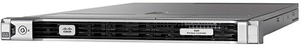
Cisco 5520 WLC Front Panel View
Cisco 5520 wireless LAN controller supports several buttons, LED indicators, and a KVM connector on the front panel. It also includes a power button and Locator LED button, along with the following LEDS: System status, PSU status, Fan status, Network LED, and Temperature LED.
Power On Switch and LED Indicator
A Power Button push switch with integrated LED is located on the front panel.
|
LED Indicator Color |
Function |
|
|---|---|---|
|
Bi-color Yellow (Amber) Green |
Card Power Status |
|
|
State |
Decode |
|
|
Off |
Card Power Off |
|
|
Amber On |
Soft Off |
|
|
Green On |
Card Power On |
|
Locator Switch and LED Indicator
A Unit Identify push switch with integrated LED is available on the front panel and rear panel . Each press on the button toggles between active and non-active states.
System Status LED Indicator
The system status LED located on the front panel indicates the overall system health.
|
LED Indicator Color |
Function |
|
|---|---|---|
|
Bi-color Yellow (Amber) Green |
System Status |
|
|
State |
Decode |
|
|
Off |
Undefined |
|
|
Green On |
Card is in normal operating condition |
|
|
Amber On |
System is in a degraded operational state |
|
|
Amber Blinking |
Critical fault state |
|
Fan Status LED Indicator
The Fan status LED located on front panel indicates the fan health.
|
LED Indicator Color |
Function |
|
|---|---|---|
|
Bi-color Yellow (Amber) Green |
Fan Status |
|
|
State |
Decode |
|
|
Off |
Undefined |
|
|
Green On |
Fans are operating and no error condition has been detected |
|
|
Amber On |
Fans are in a
degraded operational state
|
|
|
Amber Blinking |
Critical fault
state
|
|
Note |
Adaptive fan speed to control noise issues seen with 5520 FCS hardware is introduced in release version 8.1.131.0. |
Temperature Status LED Indicator
The temperature status LED is located on the front panel and indicates whether or not the system is operating within acceptable temperature limits.
|
LED Indicator Color |
Function |
|
|---|---|---|
|
Bi-color Yellow (Amber) Green |
Temperature Status |
|
|
State |
Decode |
|
|
Off |
Undefined |
|
|
Green On |
System is operating at normal temperature |
|
|
Amber On |
One or more temperature sensors reaches UCR threshold |
|
|
Amber Blinking |
One or more temperature sensors reaches UNR threshold |
|
Power Supply Status LED Indicator
The power supply status LED is located on the front panel and indicates proper functioning of the power supply.
|
LED Indicator Color |
Function |
|
|---|---|---|
|
Bi-color Yellow (Amber) Green |
AC Power Supply Status |
|
|
State |
Decode |
|
|
Off |
Undefined |
|
|
Green On |
AC power supplies are operating and no error condition has been detected |
|
|
Amber On |
One or more power supplies are in a degraded operational state |
|
|
Amber Blinking |
One or more power supplies are in a critical fault state |
|
Network Link LED Indicator
The network LED is located on the front panel and indicates if any of the on-board networking ports are connected and operating.
|
LED Indicator Color |
Function |
|
|---|---|---|
|
Single Color Green |
Network Link Status |
|
|
State |
Decode |
|
|
Off |
Undefined |
|
|
Green On |
Link on any of the ports, but no activity |
|
|
Green Blinking |
Activity on any of the ports |
|
Front Panel KVM Break-out Connector
A single female connector provides access to video, two USB ports for keyboard and mouse, and an RS-232C console serial port.
An external breakout connector to industry standard interfaces is required. The following figure shows an example cable.
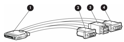
The interfaces for the cable are:
-
Front panel KVM/Console connector
-
DB9 serial port connector
-
Dual Type-A USB 2.0 connectors
-
DB15 Video connector
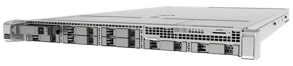
Cisco 5520 WLC Rear Panel View
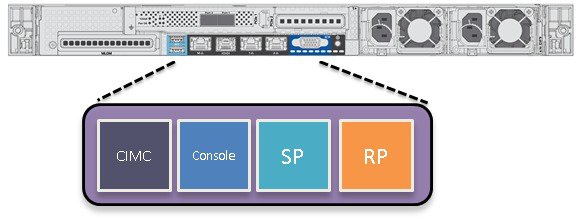
The rear panel has the following interfaces:
-
Two Type A 3.0 USB ports
-
IMC port 10/100/1000 Base-T
To setup the CIMC interface:-
Connect the CIMC cable.
-
To enable DHCP to set the IP, use the command imm dhcp enable.
-
If DHCP is not available, use the command imm address <ip address> <net mask> <gateway ip>.
-
To view the IP and details, use the command imm summary.
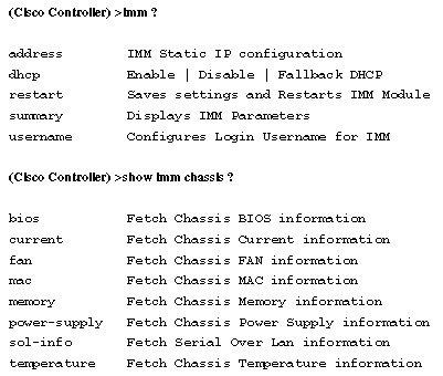
Note
CIMC web interface is for advanced debugging for TAC and escalation use only. Changing of settings in the CIMC by customer can cause adverse impact on controller software and functionality.
-
-
SerialCOM connector — Standard RS-232 Serial COM port using RJ-45 connector
-
Ethernet service port (SP) — Management 10/100/1000 Base-T
-
Redundancy Port (RP)
LED Indicator Color
Function
Bi-color Yellow
(Amber)
Green
Management Interface Port Speed
State
Decode
Off
Link Speed = 10 MbpS
Amber On
Link Speed = 100 MbpS
Green On
Link Speed = 1 GbpS
LED Indicator Color
Function
Bi-color Yellow
(Amber)
Green
Management Interface Port Status
State
Decode
Off
No Link
Green On
Link
Blinking
Traffic Present
-
VGA Connector — Rear panel has a standard VGA port using a female D-Sub-15 Connector
-
ID Switch and LED
-
Two 1/10 G Management and Network ports
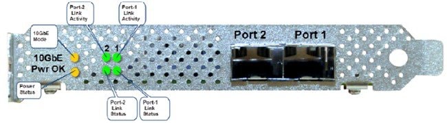
LED
Functional Definition
Pwr OK
LED: (Amber) On indicates power is good
10 G
LED: (Amber) On indicates 10 G mode
LED: Off indicates 1 G mode
Port-n Link Status
Green On—Link is up in 10Gbe Mode
Amber On—Link is up in 1 Gbe Mode
Off—Link status is down
Port-n Link Activity
LED: (Green) blinking indicates link activity
Switching Between 10 G and 1 G
-
If there is nothing installed in port 1, the board will be configured for 10 G mode by default. Therefore, to switch to 1 G mode, an SFP module must be installed in port 1 and the system needs to be rebooted.
-
Conversely, if an SFP module is installed and the user wants to switch to 4 x 10 G mode, then an SFP+ module must be installed in port 1 and the WLC rebooted.
-
Thus, Online Insertion and Removal (OIR) of SFP and SFP+ between 10 G and 1 G is not possible.
-
OIR of 10 G to 10 G and 1 G and 1 G is possible.
Note |
It is recommended to have all ports as either 10 G or 1 G. In case they are different, port 1 SFP determines the mode of operation and functionality on the other SFPs may not work. |
|
Hot Swap of SFP/SFP+ |
Port1 |
Port2 |
Remarks |
|---|---|---|---|
|
1G to 1G |
No |
Yes |
Cisco 5520 WLC requires reboot for Port1 OIR in 1G |
|
1G to 10G |
No |
No |
Cisco 5520 WLC requires reboot between 1G and 10G |
|
10G to 1G |
No |
No |
Cisco 5520 WLC requires reboot between 10G and 1G |
|
10G to 10G |
Yes |
Yes |
No reboot required |
SFP Support
Network ports for 5520 WLC support the following Cisco SFP/SFP+ modules:
-
GLC-T
-
GLC-TE
-
SFP-10G-SR
-
SFP-10G-LR
-
SFP-10G-LRM
-
SFP-H10GB-CU1M
-
SFP-H10GB-CU2M
-
SFP-H10GB-CU2-5M
-
SFP-H10GB-CU3M
-
SFP-H10GB-CU5M
-
SFP-H10GB-ACU7M
-
SFP-H10GB-ACU10M
-
SFP-10G-AOC7M
-
SFP-H10GB-CU1-5M
-
SFP-10G-AOC3M
-
SFP-10G-AOC1M
-
SFP-10G-AOC2M
-
SFP-10G-AOC5M
-
SFP-10G-AOC10M
-
GLC-LH*
-
GLC-EX-SMD*
-
GLC-SX-MMD*
-
SFP-10G-SR-S
-
SFP-10G-LR-S
Note |
*Needs GLC-T on Port 1. |
Image Specifications
Cisco 5520 WLC supports all the features of release 8.1.
Feature Not Supported on 5520 Controller Platform
The following features are not supported on the 5520 controller platform:
-
Internal DHCP server
Note |
When AP manager is configured on a dynamic interface and not on the management interface on a 5520 and when both of these interfaces are on the same port (or LAG), web redirect for web-auth will not work.Disable the AP manager on the dynamic interfaces and set it back to the management interface. |
Fault Tolerance Capability
The Cisco 5520 supports the stateless N+1 redundancy model . The N+1 HA architecture provides redundancy for controllers across geographically separate data centers with low cost of deployment. A single backup controller can be used to provide backup for multiple primary WLCs.
For more information on this model of redundancy, refer to http://www.cisco.com/c/en/us/td/docs/wireless/technology/hi_avail/N1_High_Availability_Deployment_Guide/N1_HA_Overview.html.
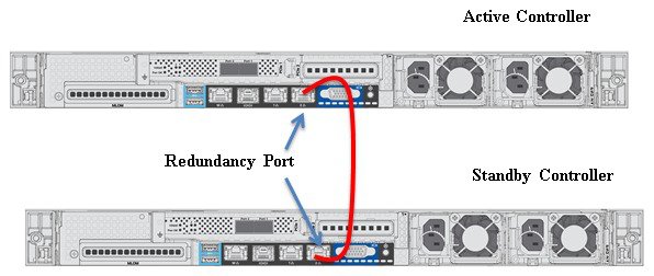
AP and Client SSO
High Availability Stateful Switchover (SSO) model provides a Box-to-Box redundancy with one controller in active state and a second controller in hot standby state. The SSO model monitors the health of the active controller via a redundant (HA) port. Cisco 5520 wireless LAN controller has a failover RP Port.
The configuration on the active controller is synched to the standby controller via the redundant port. In HA, both controllers share the same set of configuration including the IP address of the management interface. The AP's CAPWAP state (for APs in RUN state) is also synched. As a result, APs do not go into Discovery state when the active controller fails. Furthermore, a client's information is synced to the standby WLC when the client associates to the WLC or the client’s parameters change. Fully authenticated clients, that is, the ones in Run state, are synced to the standby. Thus, client re-association is avoided on switchover, making the failover seamless for the APs as well as for the clients, resulting in zero client service downtime and no SSID outage.
For more information on the SSO feature and the supported topologies, refer to the High Availability deployment Guide.
Connecting Cisco 5520 SSO Pair to the Wired Network
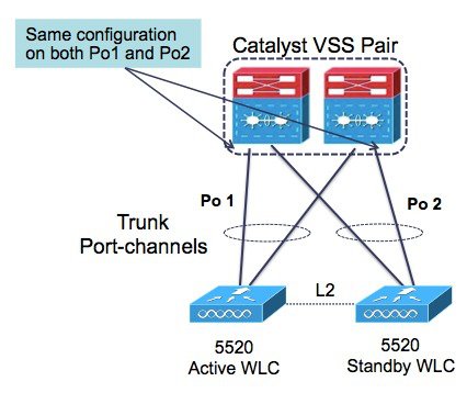
It is recommended to connect to a VSS pair and spread the links in each port-channel between the two physical switches to prevent a WLC switchover upon a failure of one of the VSS switches.
Customer Replaceable Units
Cisco 5520 wireless LAN controller has a minimal amount of separate orderable items, including all of the following:
-
Power supply
-
SSD Hard Disk Drive (HDD)
-
Option to add a redundant power supply on the Cisco 5520 WLC
Note |
The power supply units are field replaceable. |
Link Aggregation (LAG)
A single LAG across the 2 x 10 G interfaces is supported in software versions 8.1 and later. LACP and PAgP are not supported on the controller.
Inter-Platform Mobility and Guest Anchor Support
Guest anchor capability with:
-
Cisco WLC 2504/5508 / 8510 / 7510 / WISM2 running as a foreign controller (EOIP Tunnel)
-
Cisco 5520 / 8540 WLC running as a foreign controller (EOIP Tunnel)
-
Cisco 5760 WLC running as a foreign controller with new mobility turned on (CAPWAP Tunnel)
Foreign controller to a guest anchor which is a:
-
Cisco WLC 2504/5508 / 8510 / 7510 / WISM2 (EOIP Tunnel)
-
Cisco 5520 / 8540 WLC (EOIP Tunnel)
-
Cisco 5760 WLC with new mobility turned on (CAPWAP Tunnel)
CAPWAP has native management plane encryption and optional data payload encryption.
Infrastructure Multicast
Multicast support is enabled in the Cisco 5520 controller with the following restrictions:
-
If all APs on the 5520 controller are configured in Local mode, Multicast-Multicast will be the default mode and all features are supported (for example, VideoStream).
If the APs are configured as a mix of Local mode and FlexConnect mode:
-
If IPv6 is required on the FlexConnect APs:
-
Disable Global Multicast Mode and change to Multicast-Unicast mode.
-
IPv6 / GARP will work on FlexConnect and Local mode APs, but Multicast data and the VideoStream feature will be disabled.
-
-
IPv6 / GARP is not required on FlexConnect APs:
-
Change the mode to Multicast-Multicast and enable Global Multicast Mode and IGMP / MLD snooping.
-
IPv6, GARP, Multicast Data, and VideoStream are supported on local mode APs.
-
New Mobility and MC Support
Cisco 5520 supports the new mobility functionality to be compatible with inter-platform IRCM and guest anchor functionality. This platform will not function as an MC.
Look and Feel of the Cisco 5520 Wireless LAN Controller
The Cisco 5520 controller enables console redirect by default with baud rate 9600, simulating a VT100 terminal with no flow control. The 5520 Controller has the same boot sequence as existing controller platforms.
Boot Up and Initial Configuration
-
Initial Boot Sequence
-
Boot Options
-
Loading the OS and Boot Loader
-
Loading Controller Services
Initial Controller Configuration
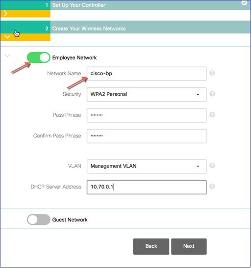
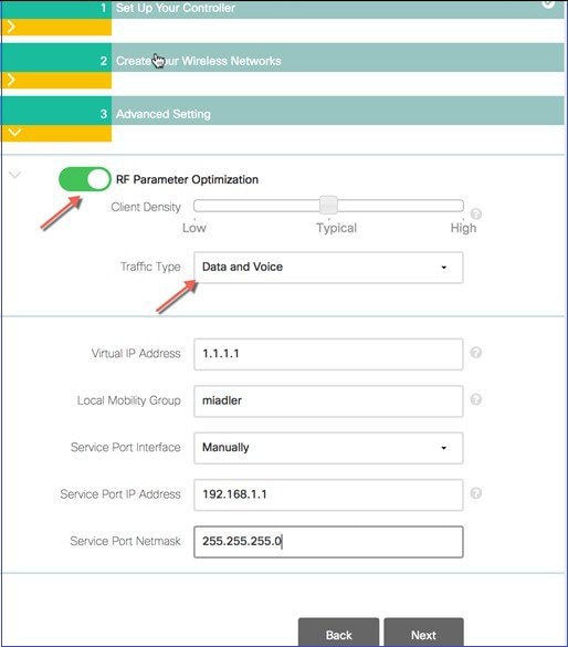
Configuration Wizard — As with all other controller platforms, initial boot up requires configuration using the Wizard menu.
WLAN Express Setup — As with all other controller platforms, 5520 WLC also supports the Express WLAN Setup over wired Ethernet connection.


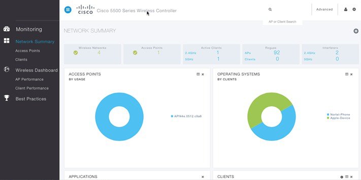
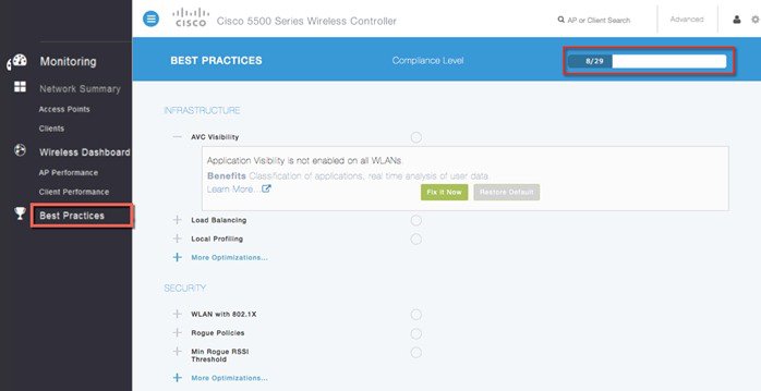
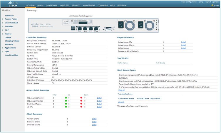
Monitoring and Best Practices
This platform supports the Monitoring Dashboard and the Upgrade audit workflow view.
The following screenshot is the Best Practices Audit workflow page.
Management Web UI
The management web interface has the same look and feel as existing Cisco wireless LAN controllers.
Out of Band Management on Service Port
Starting release 8.2 the Service Port capability on the Cisco 5520 Wireless LAN Controller has been enhanced to support the following management services:
-
HTTP/HTTPS web-based access
-
SNMP polling v2 and v3
-
Syslog
-
SSH or Telnet
-
Transfer download and upload
These services shall be supported in a non-HA topology only in this release
Service Port

Service Port Configuration
The IP address assigned to the service port must be in a non-routable subnet different from the Management subnet. It can be assigned dynamically or statically as shown in the configuration below. There is no change in the service port configuration itself and the commands below are for your reference.
Use the following commands to define the Service port interface with an IPv4 address:
Dynamic assignment of IPv4 address on the Service Port:
-
To configure the DHCP server:
config interface dhcp service-port enable -
To disable the DHCP server:
config interface dhcp service-port disable -
To configure a static IPv4 address on the Service Port use the following command:
config interface address service-port ip-address netmask -
To add an IPv4 route to allow out-of-band management of the controller from a remote workstation:
config route add network-ip-address ip-netmask gateway -
To remove the IPv4 route on the controller:
config route delete network-ip-address
Use the following commands to define the Service port interface with an IPv6 address:
-
To configure the service port using slacc:
config ipv6 interface slacc service-port enable -
To disable the service port using slacc:
config ipv6 interface slacc service-port disable -
To configure the IPv6 address:
config ipv6 interface address service-port ipv6-address prefix-length -
To add an IPv6 route to allow out-of-band management of the controller from a remote workstation:
config ipv6 route add network_ipv6_address prefix-length ipv6_gw_addr -
To remove the IPv4 route on the controller:
config ipv6 route delete network_ipv6_address - To verify the status of the service port after configuration
show interface detailed service-port Limitations
-
RADIUS, TACACS+ and NMSP to MSE via Service Port not supported in release 8.2
-
SP Port OOB Management cannot be enabled when the WLC is in an SSO Pair.
Local EAP Support
Starting Software release 8.2, Cisco 5520 Wireless LAN Controller supports the Local EAP functionality natively on the controller.
Local EAP is an authentication method that allows users and wireless clients to be authenticated locally on the controller. It is designed for use in remote offices that want to maintain connectivity to wireless clients when the backend system becomes disrupted or the external authentication server goes down. When you enable local EAP, the controller serves as the authentication server and the local user database, so it removes dependence on an external authentication server. Local EAP retrieves user credentials from the local user database or the LDAP backend database to authenticate users. Local EAP supports LEAP, EAP-FAST, EAP-TLS, PEAPv0/MSCHAPv2, and PEAPv1/GTC authentication between the controller and wireless clients.
The configuration of Local EAP remains the same as on existing WLCs. A Local EAP Server Configuration Example can be found at http://www.cisco.com/c/en/us/support/docs/wireless-mobility/wlan-security/91628-uwn-loc-eap-svr-config.html%23maintask1
Wired Guest Access Support
Starting Software release 8.2, Cisco 5520 Wireless LAN Controller supports the Wired Guest Access functionality.
A growing number of companies recognize the need to provide Internet access to its customers, partners, and consultants when they visit their facilities. IT managers can provide wired and wireless secured and controlled access to the Internet for guests on the same wireless LAN controller. Guest users must be allowed to connect to designated Ethernet ports and access the guest network as configured by the administrator after they complete the configured authentication methods. Wireless guest users can easily connect to the WLAN Controllers with the current guest access features. This provides a unified wireless and wired guest access experience to the end users.
Wired guest ports are provided in a designated location and plugged into an access switch. The configuration on the access switch puts these ports in one of the wired guest Layer 2 VLANs.
Two separate solutions are available to the customers:
A single WLAN controller (VLAN Translation mode)–the access switch trunks the wired guest traffic in the guest VLAN to the WLAN controller that provides the wired guest access solution. This controller carries out the VLAN translation from the ingress wired guest VLAN to the egress VLAN.
Two WLAN controllers (Auto Anchor mode) - the access switch trunks the wired guest traffic to a local WLAN controller (the controller nearest to the access switch). This local WLAN controller anchors the client onto a Demilitarized Zone (DMZ) Anchor WLAN controller that is configured for wired and wireless guest access. After a successful handoff of the client to the DMZ anchor controller, the DHCP IP address assignment, authentication of the client, and so on are handled in the DMZ WLC. After it completes the authentication, the client is allowed to send and receive traffic.
The configuration of Wired Guest Access remains the same as on existing WLCs. A Wired Guest Access Configuration Example can be found at http://www.cisco.com/c/en/us/support/docs/wireless-mobility/wireless-lan-wlan/99470-config-wiredguest-00.html
Licensing
5520 wireless LAN controller supports Right to Use (RTU) licensing model similar to the Cisco Flex 7500 and Cisco 8500 series controllers. This is an Honor-based licensing scheme that allows AP licenses to be enabled on supported controllers with End User License Agreement (EULA) acceptance. The RTU license scheme simplifies addition, deletion, or the transfer of AP adder licenses in the field by eliminating the need for an additional step, additional tools, or access to Cisco.com for PAK license or return materials authorization (RMA) transfers.
Evaluation licenses are valid for 90 days. Notifications will be generated to inform you to buy a permanent license starting 15 days prior to the evaluation license expiration.
If you have more APs connected than those purchased, the licensing status for the controller tracked within the Cisco Prime Infrastructure will turn red.
For more information on the RTU License model, refer to the Cisco Right to Use Licensing (RTU) document.
Smart Licensing is also available, for more information refer to http://www.cisco.com/c/en/us/td/docs/wireless/technology/mesh/8-2/b_Smart_Licensing_Deployment_Guide.html
License Types
These are the three license types:
-
Permanent licenses—The AP count is programmed into NVM while manufacturing. These licenses are transferable.
-
Adder access point count licenses—Can be activated through the acceptance of the EULA. These licenses are transferable.
-
Evaluation licenses—Used for demo and/or trial periods, are valid for 90 days, and default to the full capacity of the controller. The evaluation license can be activated at any time using a CLI command.
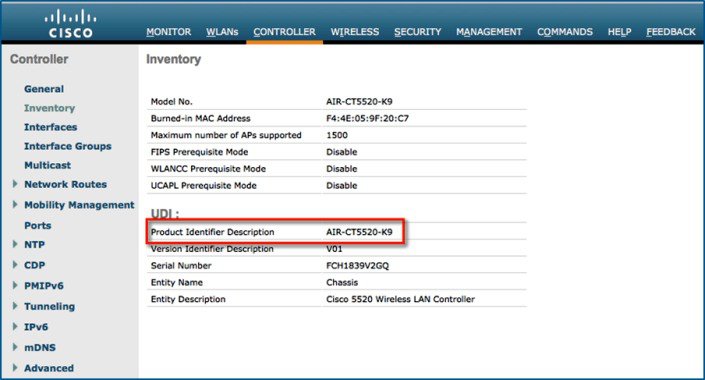
Licensing Model Features
-
Two Base Bundle SKUs: AIR-CT5520-K9 and AIR-CT5520-50-K9
-
Portability of licenses between 5520 and 8540 wireless LAN controllers
-
No separate HA-SKU UDI
|
SKU / PID |
Description |
Comments |
|---|---|---|
|
AIR-CT5520-K9 |
Cisco 5520 wireless controller w/rack mounting kit |
Base and HA SKU |
|
AIR-CT5520-50-K9 |
Cisco 5520 wireless controller supporting 50 APs w/rack kit |
50 AP Bundle SKU |
|
LIC-CT5520-UPG |
Top level SKU for 5520 AP adder licenses |
— |
|
LIC-CT5520-1A |
Cisco 5520 wireless controller 1 AP adder license |
— |
 Feedback