Introduces the hardware architecture of access points, detailing physical views, connector and port types, environment packs, cabling guidelines, LED status indicators, and instructions for using the reset button.
Access point views
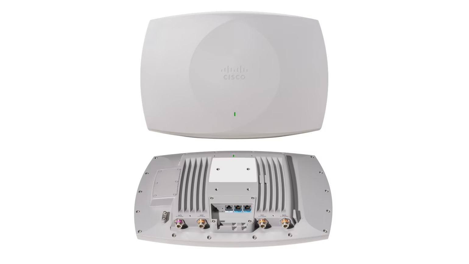
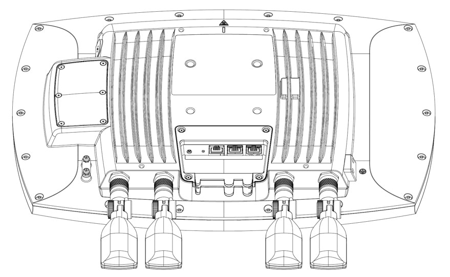
For information about connectors and ports for the AP models, see Types of connectors and ports on the access point.
Types of connectors and ports on the access point
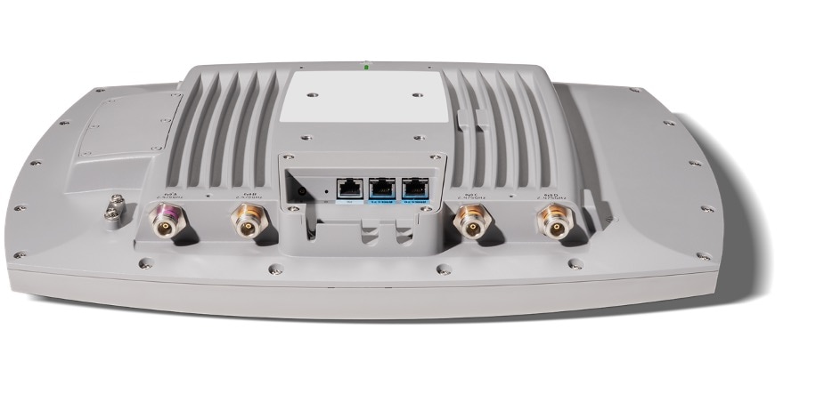
These figures show the available ports on the AP:
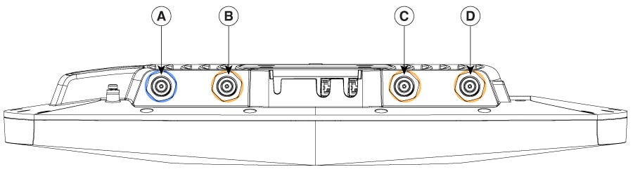
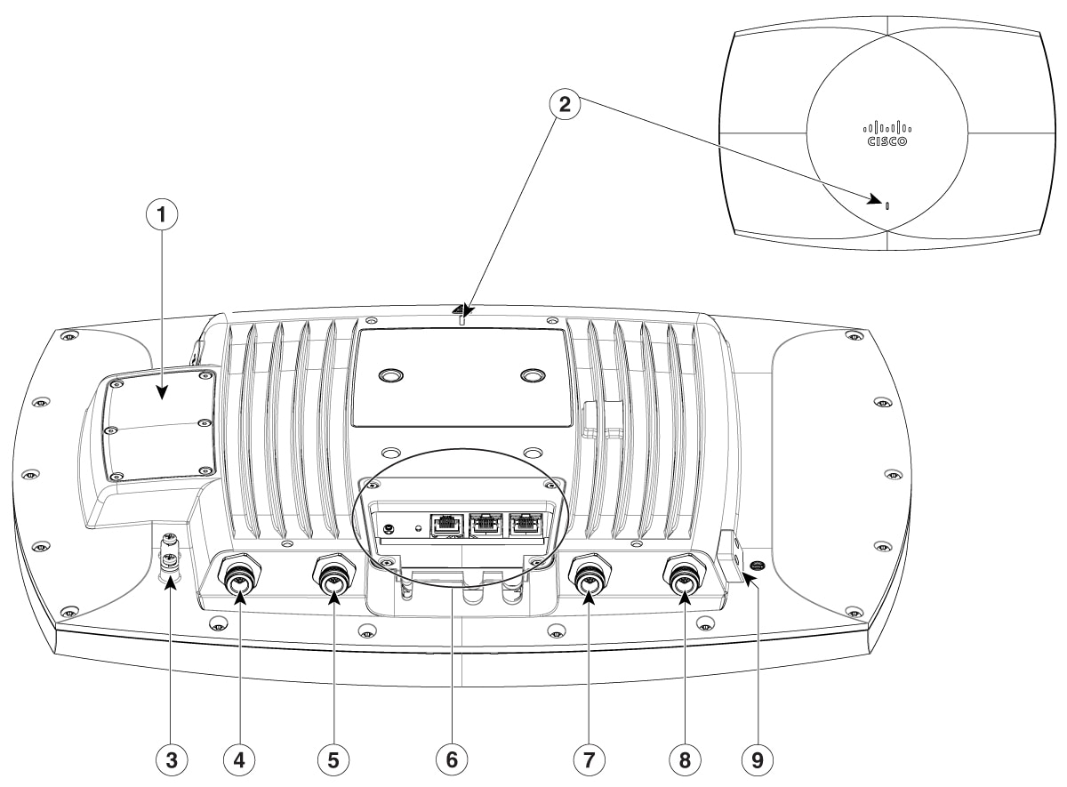
|
1 |
Internal GNSS Rear Antenna (with non-removable cover) |
6 |
Environment Pack |
|
2 |
Status LED |
7 |
Port C 2.4/5 GHz (Orange Ring) |
|
3 |
Safety Tether Anchor |
8 |
Port D 2.4/5 GHz (Orange Ring) |
|
4 |
Port A 2.4/5 GHz (Purple Ring) |
9 |
Ground Lug Mount |
|
5 |
Port B 2.4/5 GHz (Orange Ring) |
||
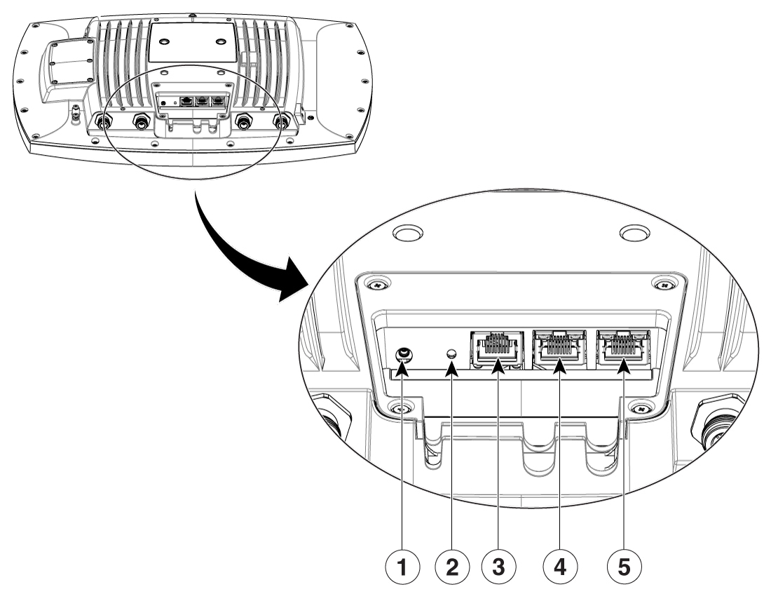
|
1 |
External GNSS (MMXC) |
4 |
Port 1 |
|
2 |
Reset Button |
5 |
Port 0 |
|
3 |
Console Port |
||
Non-LAG mode: For a single uplink, connect the switch to Port 0. Port 0 is the active port and Port 1 is the standby port. Only the active port carries normal traffic. Connecting only to Port 1 may prevent the access point from obtaining a DHCP address or joining the controller
Environment Pack
Cisco Wireless 9179F Wi-Fi 7 Access Point supports both indoor and outdoor environment packs. The Environment Pack weatherizes the device and signals to the access point that it is operating at standard power only.
Indoor Environment Pack
Indoor Environment Pack: CW-ACC-9179-A-00
The default access point configuration includes a pre-installed indoor environment pack.
-
When installed, the access point operates in either LPI or SP mode.
-
The access point comes with the environment pack installed.
Outdoor Environment Pack
Outdoor Environment Pack: CW-ACC-9179-B-00
-
When installed, the access point changes to SP-only mode (for 6 GHz, where allowed).
-
Seal the environment pack cavity and cables to IP65 / IP67 standards.
-
Includes an environment pack cover with an environmental seal, two rubber cable glands (6–7 mm OD and 7–8 mm OD), and weatherization tape for use with external antenna connections.
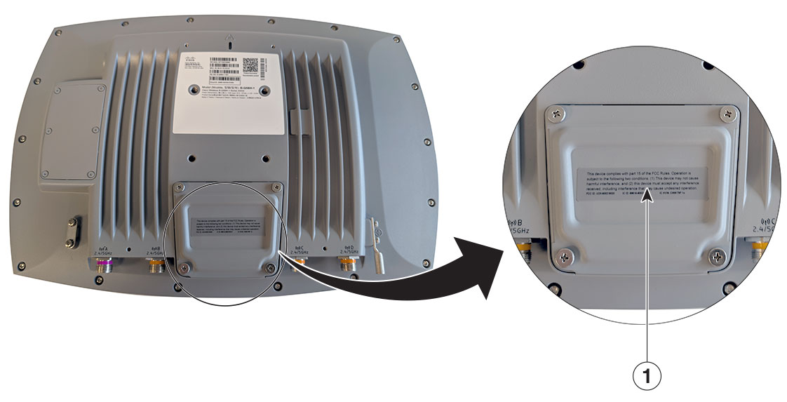
|
1 |
Outdoor Environment Pack (with an environmental seal) |
Cabling
The use of proper cable types will enhances the performance of the CW9179F. Since this access point has 10-Gbps ports, it is recommended to use either CAT6 or CAT 6a cable which support speeds of up to 10 Gbps. CAT 5e cables can still be used; however, the access point's performance may get degraded.
This table lists the various cable types that can be used with the CW9179F.
| Cable Type | Speeds | Maximum Length |
|---|---|---|
|
CAT 5e |
5 Gigabit |
328 feet (100 meters) |
|
CAT 6 |
1/2.5/5 Gigabit |
330 feet (100 meters) |
|
10 Gigabit |
164 feet (50 meters) |
|
| CAT 6a |
10 Gigabit |
330 feet (100 meters) |
LED status indications for access point
The location of the access point status LED is shown in Types of connectors and ports on the access point.
Regarding LED status colors, it is expected that there might be small variations in color intensity and hue from unit to unit. This is within the normal range of the LED manufacturer’s specifications and is not a defect. However, the intensity of the LED can be changed through the controller.
When the AP is in Meraki management mode, the LED status indicators convey the status differently from the Cisco APs.
The access point status LED indicates various conditions, which are described in the following table.
|
AP Operating Mode When in on-prem/Catalyst mode |
||
|---|---|---|
|
Message Type |
LED State |
Message Meaning |
|
Boot loader status |
Blinking green 
|
Boot loader executing |
|
Association status |
Green 
|
Normal operating condition, but no wireless client is associated |
|
Blue 
|
Normal operating condition, at least one wireless client is associated |
|
|
Cycling through Green-red-off 
|
Discovery/join in progress |
|
|
Cycling through Blue-green-red  
|
AP location command |
|
|
Blinking red 
|
Ethernet link not operational |
|
|
Red 
|
Ethernet failure |
|
|
Blinking blue
|
Configuration recovery in progress |
|
|
Boot loader warnings |
Red
|
Image recovery |
|
Environment pack error |
Cycling through Green-White-Red-Green-White-Red Blinking 
|
Error in operating condition of Environment pack |
|
AP Operating Mode When in GUAPO/Meraki mode |
||
|---|---|---|
|
Message Type |
LED State |
Message Meaning |
|
Boot/Hardware Issue |
Orange 
|
AP is booting (permanent Orange suggests hardware issue) |
|
Initializing/Scanning |
Rainbow 
|
AP is initializing/scanning |
|
Upgrading |
Blinking Blue
|
AP is upgrading |
|
Gateway Ready (Idle) |
Green
|
AP in Gateway mode with no clients |
|
Gateway Active |
Blue
|
AP in Gateway mode with clients |
|
No Uplink/Connection Issue |
Blinking Orange 
|
AP can't find uplink |
|
Environment pack error |
Cycling through Green-White-Red-Green-White-Red Blinking
|
Error in operating condition of Environment pack |
Red states relate to manufacturing, RMA, or RI. For some older axe boards or builds, initiate the diagnostic image download process. The LED flashes blue and green while it downloads the diagnostic image.
|
Message Type |
LED State |
Message Meaning |
|---|---|---|
|
Ethernet Port 0/1 LED |
Green
|
Ethernet link established at 10G/5G/2.5G/1G/100M |
|
Orange
|
Ethernet link at 1G/100M |
|
|
Blinking green
|
Data transmission is at 10G/5G/2.5G |
|
|
Blinking orange
|
Data transmission at 1G/100M |
Reset access point
Using the Reset button (see Types of connectors and ports on the access point), you can reset the AP to factory default.
To reset the AP to the default factory-shipped configuration, perform the following steps:
-
Unplug the AP from the power source.
-
Hold the Reset button.
-
Power on the AP.
Press, and continue to press the Reset button for the duration corresponding to your requirements listed in the table below:
Reset option
Reset pin hold time
LED status
0. Mode indication
~ 5 seconds
-
Blink green: Meraki mode
-
Blink blue: Catalyst mode
1. Config reset
> 10 seconds
Solid white
2. Full reset (maintains management mode)
> 20 seconds
Orange
3. FIPS reset (Catalyst mode only)
> 30 seconds
Solid red
4. Factory reset (back to global use AP onboarding)
> 60 seconds
Solid pink
5. Cancel reset
> 90 seconds
Not applicable
The reset operation is consistent with traditional Catalyst-managed AP deployments and is now integrated with Meraki-managed deployments.
-