Cisco Wireless 9177 Series Access Point Hardware Installation Guide

PDF

Cisco Wireless 9177 Series Access Point Hardware Installation Guide

Access point hardware features

Want to summarize with AI?

Log in

Introduces access point hardware features, detailing available connectors and ports, and explains how to interpret LED status indicators for proper hardware identification, installation, and verification.


The access point includes ports, connectors, and LED indicators that support installation, network connectivity, and service access.


Connectors and ports on the AP

The figures show the available ports on the AP.

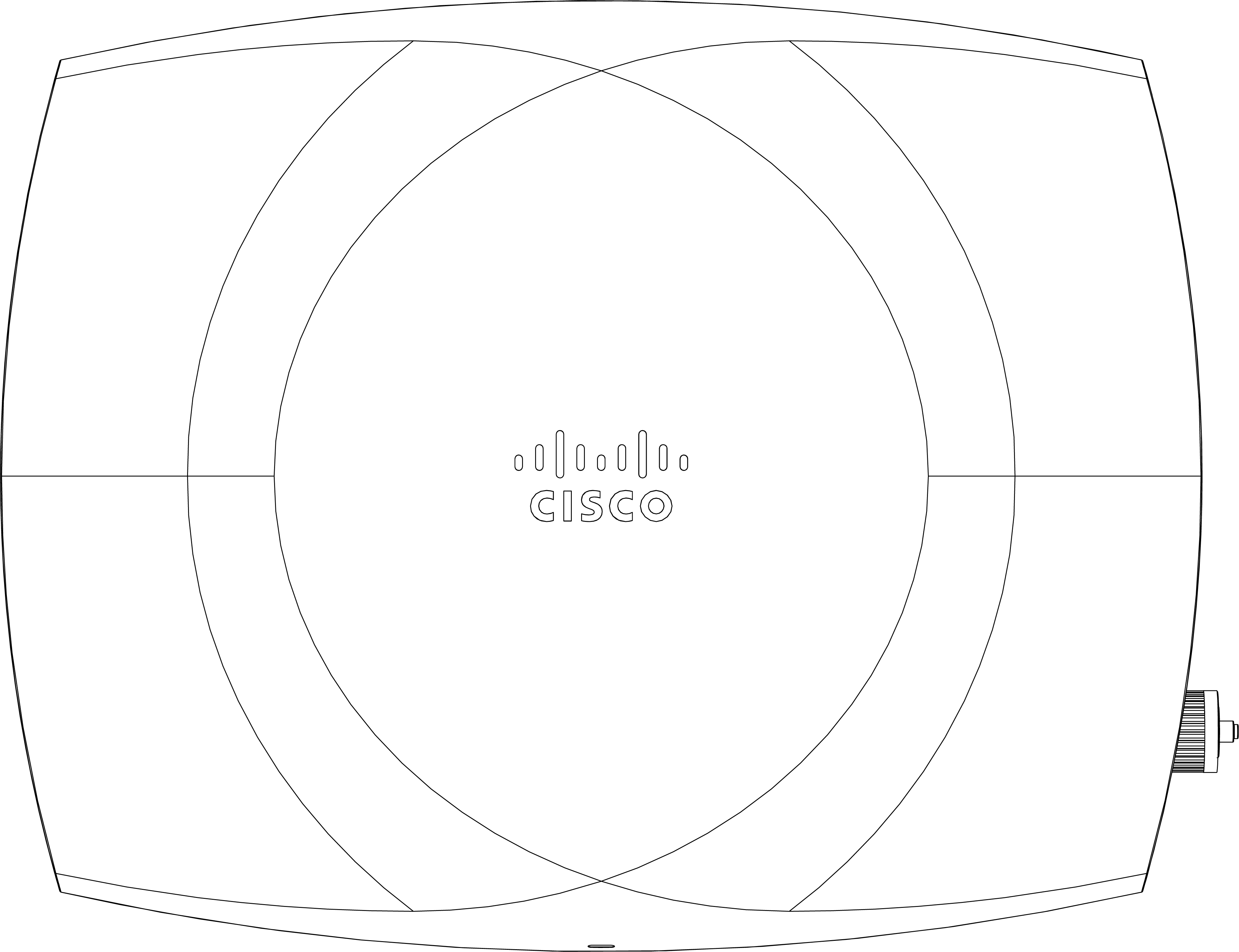
CW9177 face view

Figure 1. CW9177D and CW9177I face view

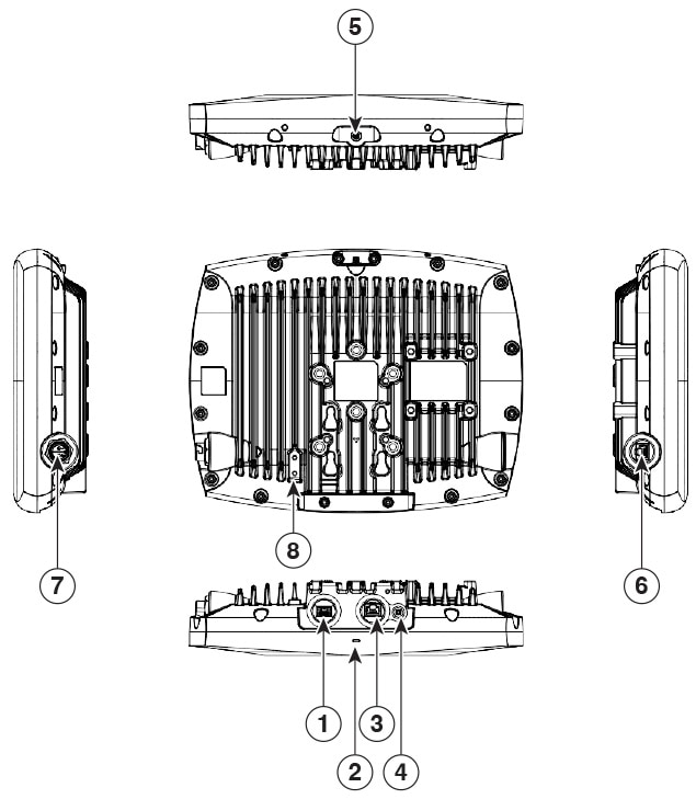
CW9177 bottom view

Figure 2. CW9177D and CW9177I bottom view with connectors and ports

1

SFP+ port

5

External GNSS port

2

Status LED

6

Console port

3

Ethernet port

7

DC power jack

4

Reset button

8

Grounding pad

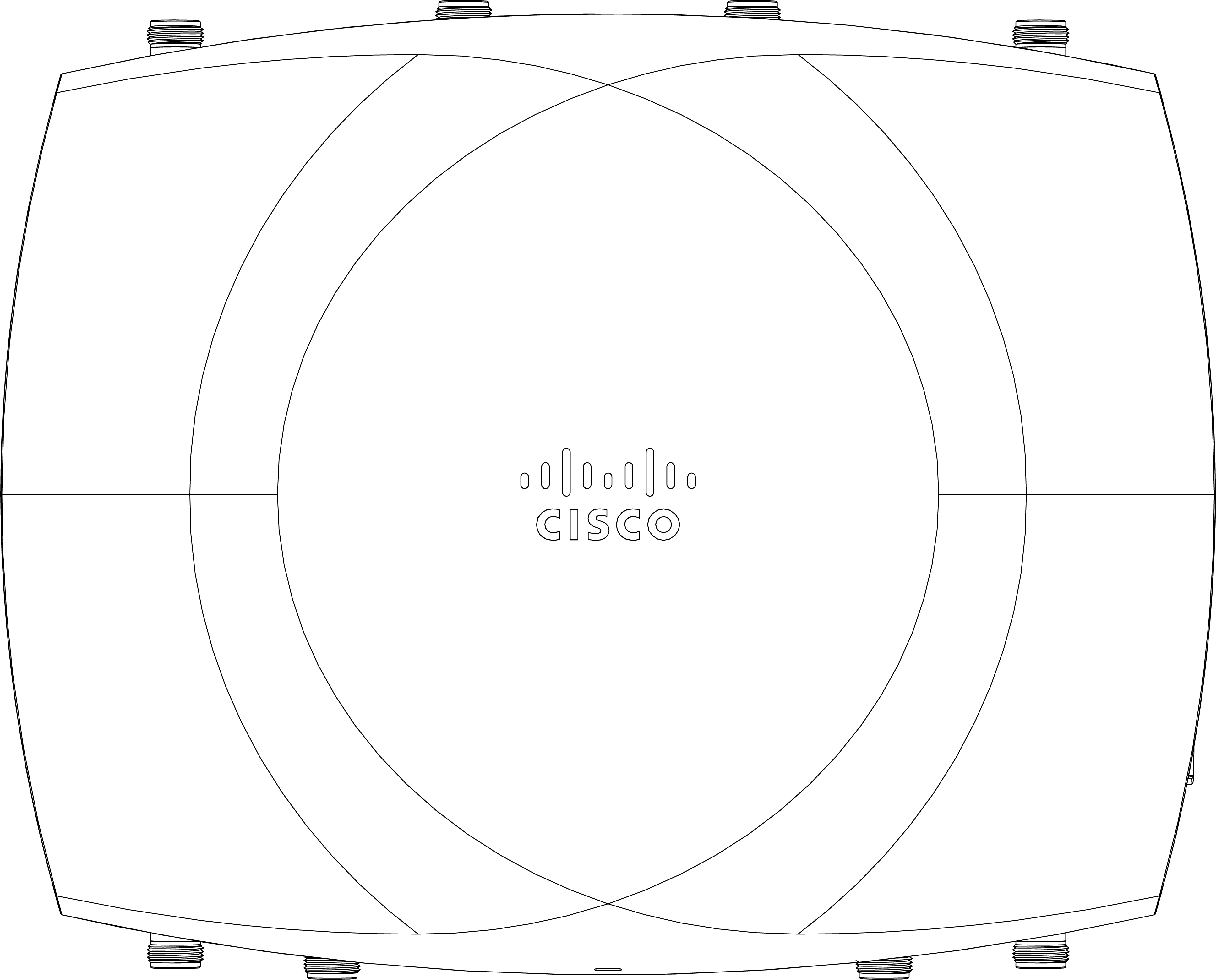
CW9177E face view

Figure 3. CW9177E face view

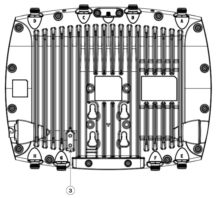
CW9177E bottom view

The CW9177E supports two configurable radio modes. The port mapping for the external antenna connectors (Ports A–H) changes based on the selected mode:

  • Radio Mode 1 (Tri-radio: 2.4/5F/6 GHz, 12ss):

    • Ports A–D: 2.4 GHz and 5 GHz full band (5F)

    • Ports E–H: 6 GHz full band

  • Radio Mode 2 (Tri-radio, dual-band: 2.4/5L/5H GHz, 12ss):

    • Ports A–D: 2.4 GHz and 5 GHz low Band (5L) (UNII-1 & 2A)

    • Ports E–H: 5 GHz high band (5H) (UNII-2C & 3)

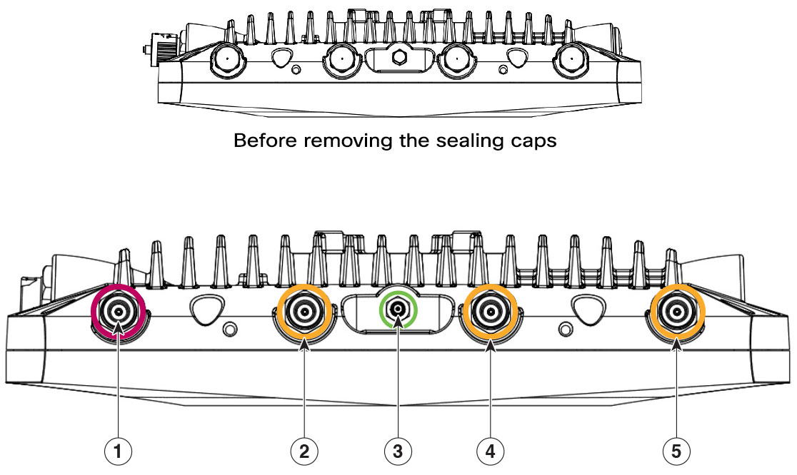
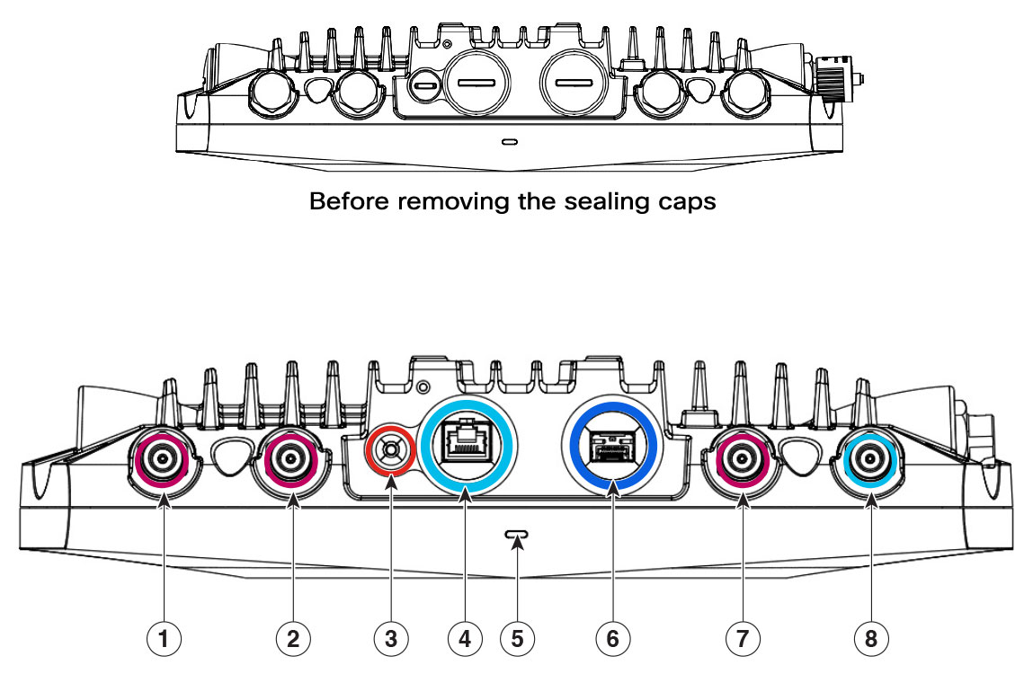
Figure 4. CW9177E view with connectors and ports

1

Port A 2.4/5 GHz + SIA

Connector type: N-female bulk head

4

Port C 2.4/5 GHz

Connector type: N-female bulk head

2

Port B 2.4/5 GHz

Connector type: N-female bulk head

5

Port D 2.4/5 GHz

Connector type: N-female bulk head

3

External GNSS (SMA)

Figure 5. CW9177E view with connectors and ports

1

Port H 5/6 GHz

Connector type: N-female bulk head

5

Ethernet port

2

Port G 5/6 GHz

Connector type: N-female bulk head

6

Reset button

3

SFP+ port

7

Port F 5/6 GHz

Connector type: N-female bulk head

4

Status LED

8

Port E 5/6 GHz + SIA

Connector type: N-female bulk head

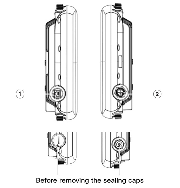
Figure 6. CW9177E side view with connectors and ports
Figure 7. CW9177E side view with connectors and ports

1

Console port

3

Grounding pad

2

DC power


LED status indications

The CW9177 APs include a multicolor system LED that shows operational status, boot progress, and network connectivity.

Note
  • LED status colors may vary in intensity and hue from one unit to another. These variations are normal and do not indicate a defect. You can adjust LED intensity using the controller.

  • In Cloud (Meraki) mode, the AP’s LED status indicators work differently than those on Cisco APs.

The access point status LED indicates several conditions. The table describes these conditions.

Table 1. LED Status indications in On-premises (Cisco Catalyst Wireless Controllers)

Type of message

State of LED

Meaning of message

System LED

Blinking green

Boot loader status includes DRAM test, board initialization, flash initialization, and starting IOS.

Green

Normal operating condition, no wireless client associated.

Blue

Normal operating condition, at least one wireless client associated.

Alternating between green and red

Discovery or join process in progress.

Blinking red

AP location command.

Red

Ethernet failure.

Blinking blue

Configuration recovery in progress. Mode button pressed for two to three seconds.

Red

Image recovery. Mode button pressed for 20 to 30 seconds.

Cycling blue, green, red, and off

General warning, insufficient inline power.

Table 2. LED status indications for Cloud (Meraki)

Type of message

State of LED

Meaning of message

Boot status

Orange

AP is booting. Permanent orange suggests a hardware issue.

Initialization status

Rainbow

AP is initializing or scanning.

Upgrade status

Blinking blue

AP is upgrading.

Gateway mode (no clients)

Green

AP in gateway mode with no clients.

Gateway mode (with clients)

Blue

AP in gateway mode with clients.

Uplink status

Blinking orange

The AP cannot detect an uplink.