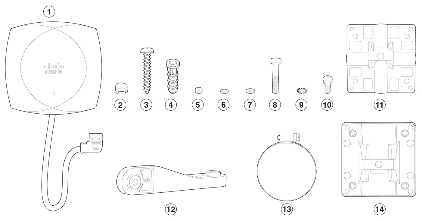
Package contents
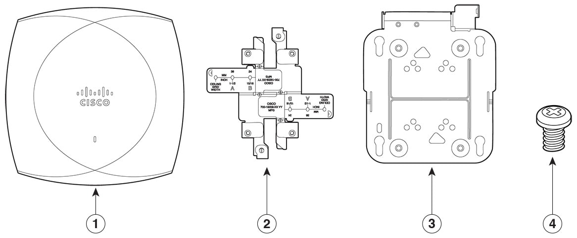
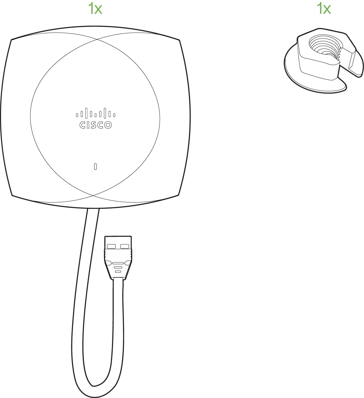
Each AP package contains the following items:
|
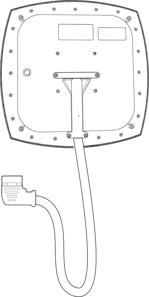
1 |
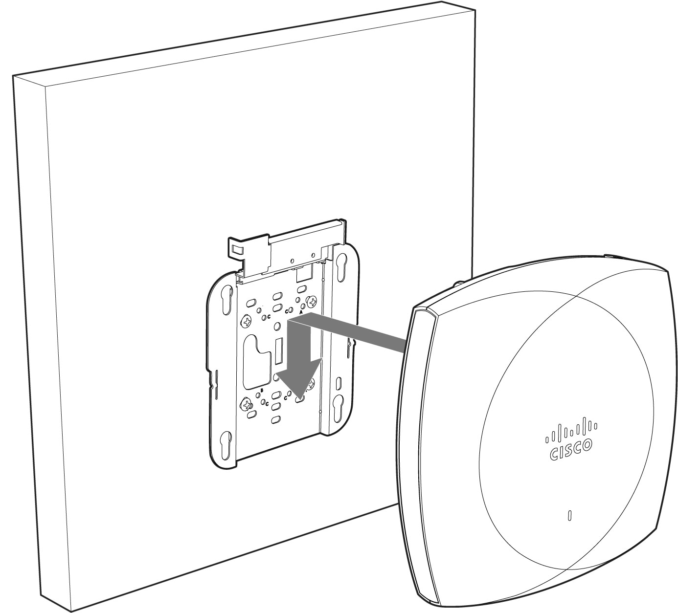
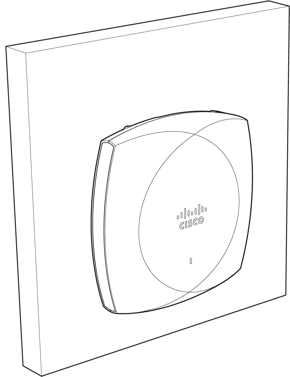
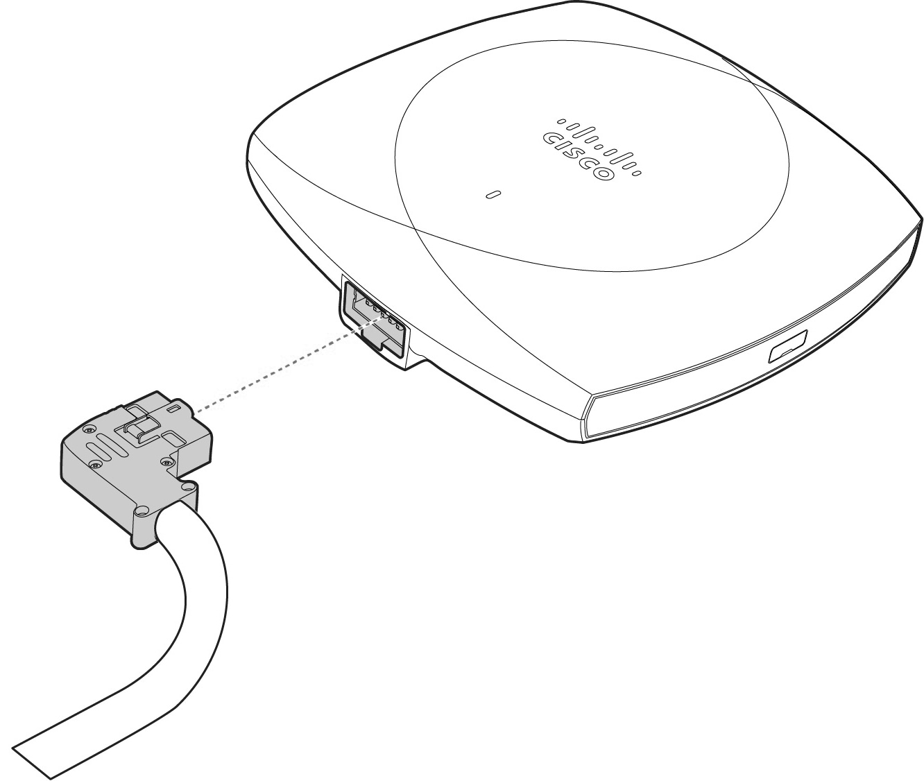
CW9174E access point |
|
2 |
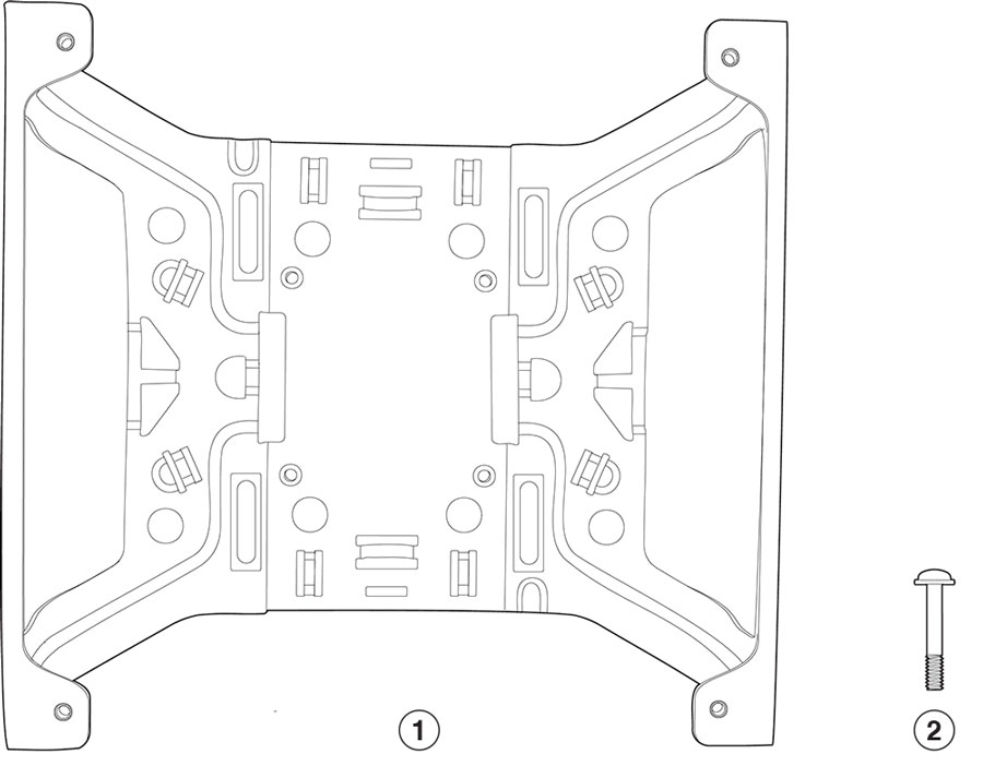
AIR-AP-T-RAIL-R |
|
3 |
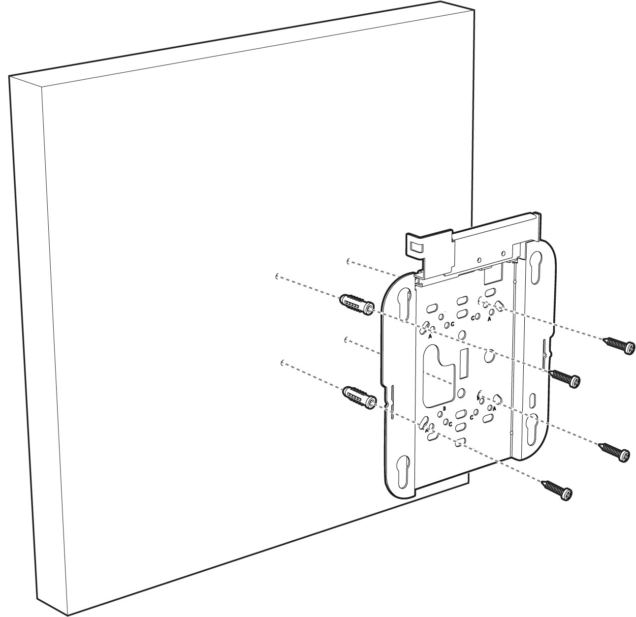
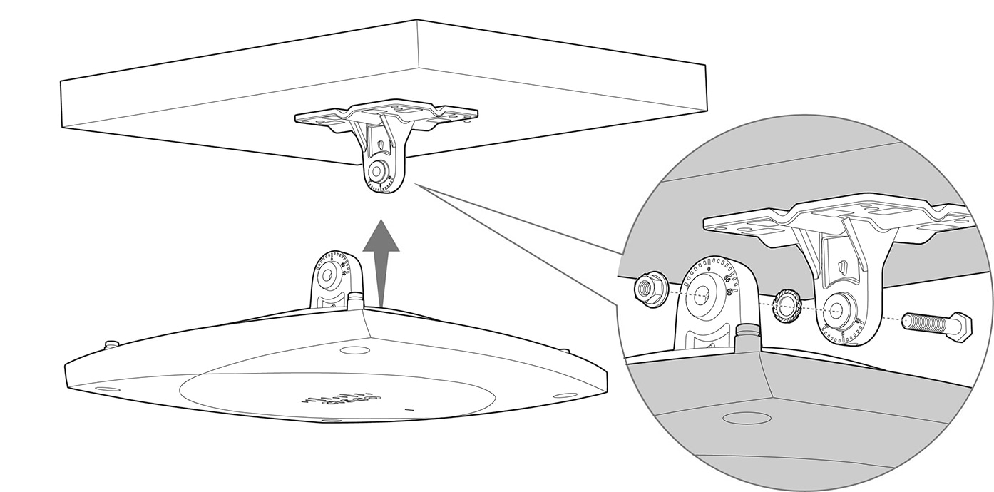
AIR-AP-BRACKET-1 |
|
4 |
Screws |
-
One CW9174E AP
-
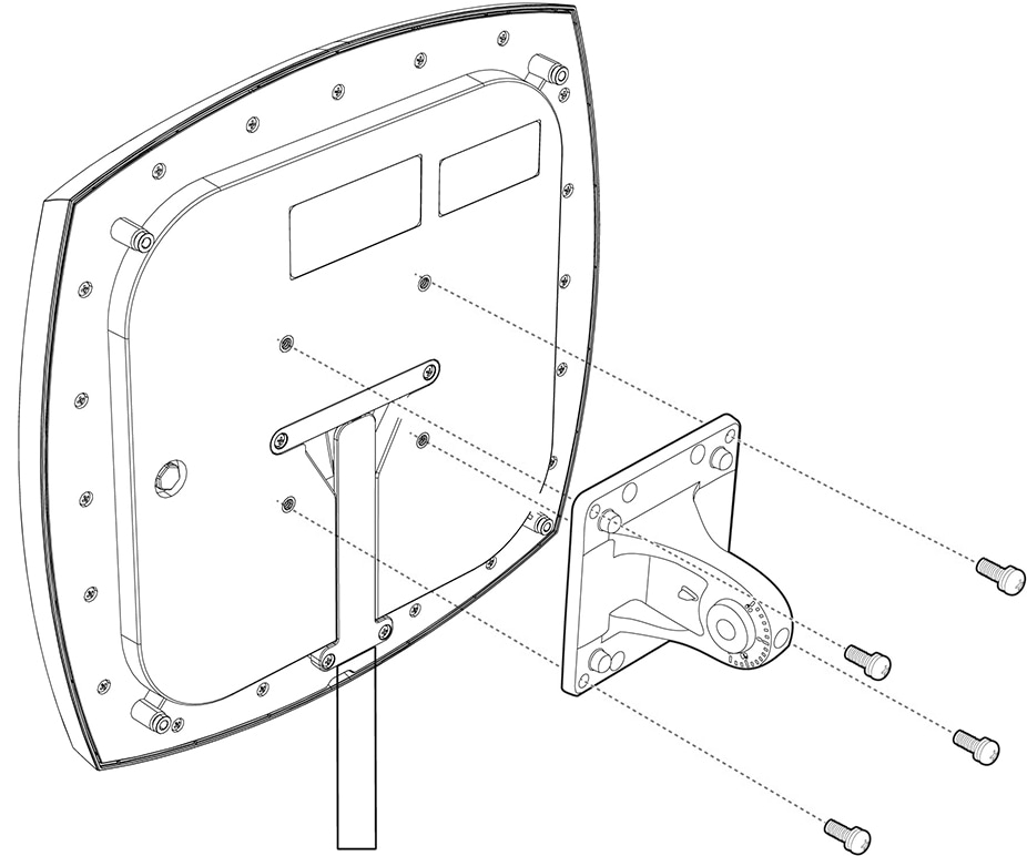
Default mounting brackets: Adjustable ceiling-rail clips AIR-AP-T-RAIL-R= and AIR-AP-BRACKET-1=
-
Orderable optional mounting brackets: AIR-AP-T-RAIL-F=, and AIR-AP-BRACKET-2=
-
Cisco product documentation and pointer card


 Feedback