Access point views, ports, and connectors
Cisco Wireless 9174E Wi-Fi 7 Access Point has multiple options that you can use to power the AP.
Connectors and ports on the AP
The following figures show the available ports on the AP:
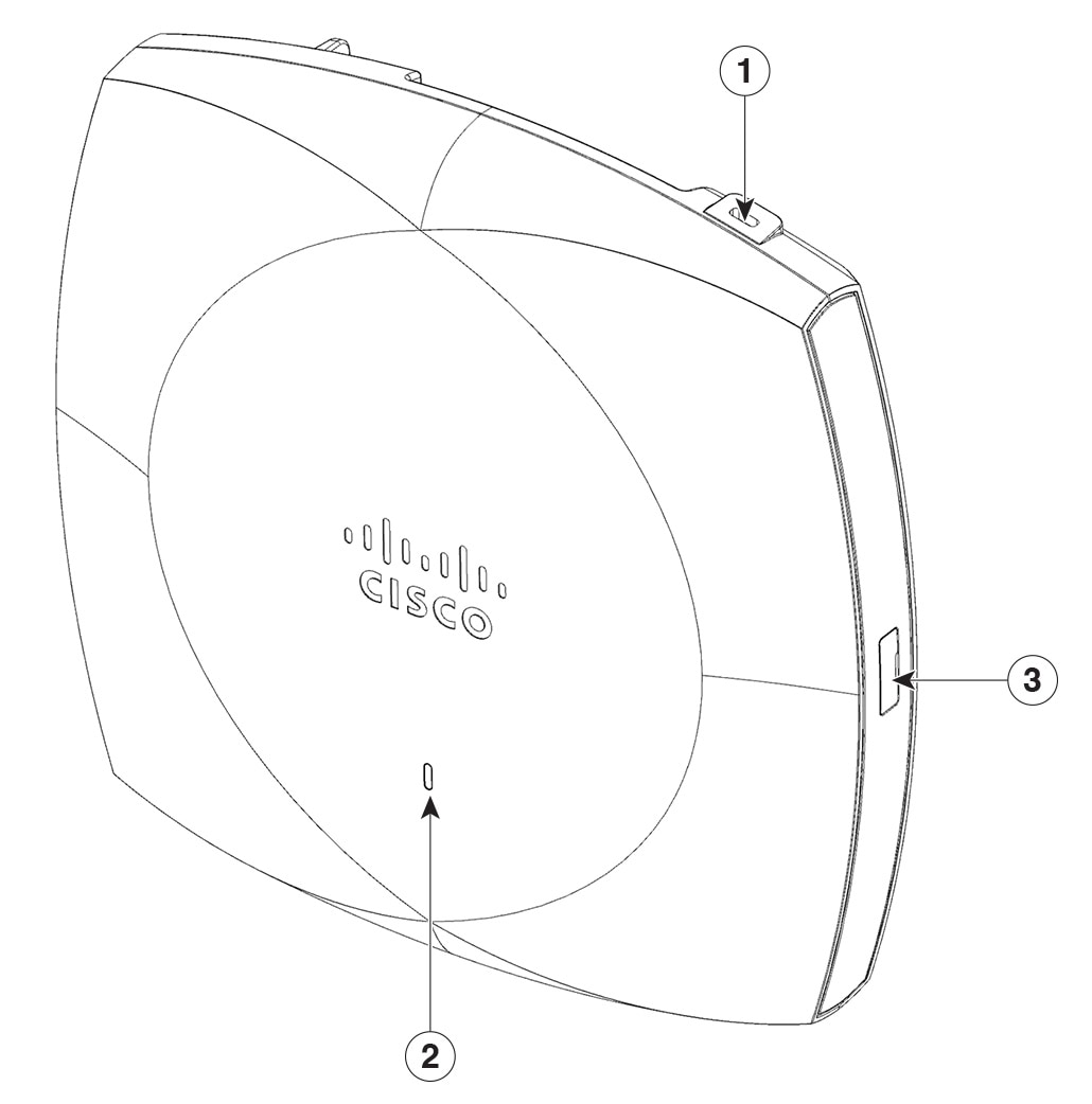
CW9174E face view
|
1 |
Kensington lock slot |
|
2 |
Status LED For information on the LED status, see LED Status Indications. |
|
3 |
USB 2.0 port |
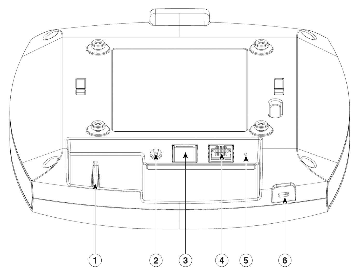
CW9174E top view
|
1 |
Security hasp for padlocking AP to mounting bracket |
4 |
Ethernet port 0 |
|
2 |
DC power jack |
5 |
Reset button For information about how to use the Reset button, see the Using the Mode Button section |
|
3 |
RJ-45 console port Default baud rate is 115200. |
6 |
Kensington lock slot |
|
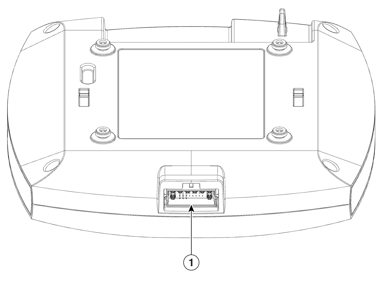
1 |
8-port Smart Antenna (DART) connector port |


 Feedback