Hardware Features

This chapter describes the hardware features of Cisco Wireless 9174I Wi-Fi 7 Access Point and contains the following sections:

Access point views, ports, and connectors

Cisco Wireless 9174I Wi-Fi 7 Access Point has multiple options that you can use to power the AP. For information about connectors and ports for the AP models, see Connectors and ports on the AP.

Connectors and ports on the AP

The following figures show the available ports on the AP:
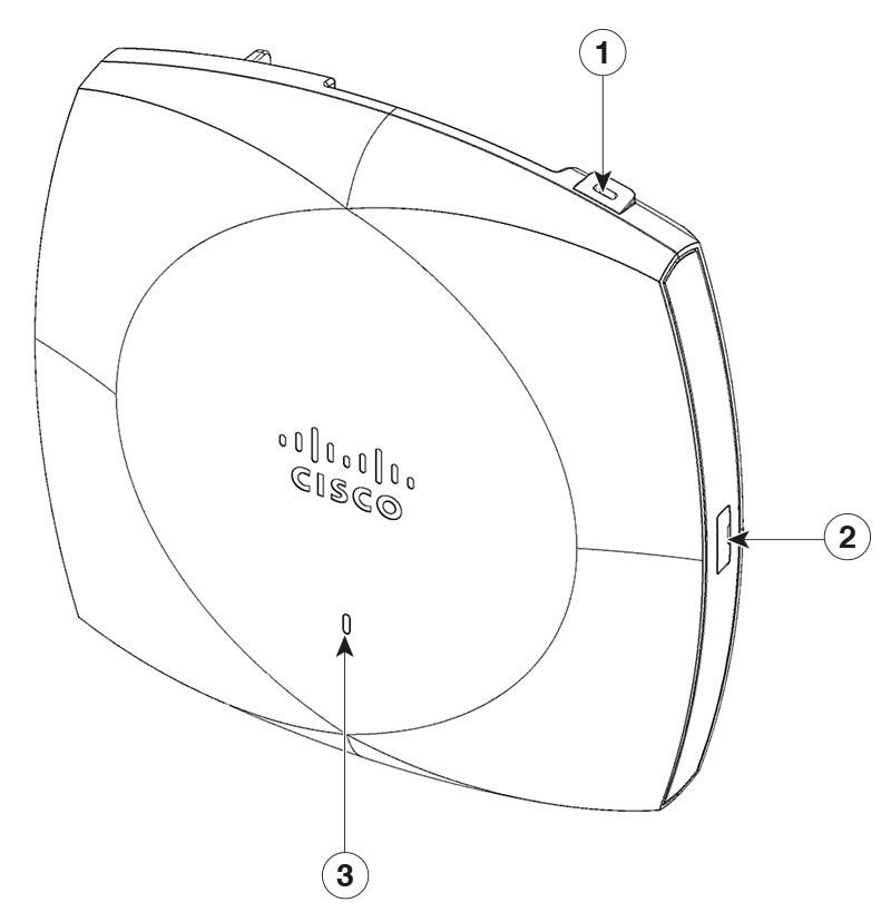
CW9174I face view

Figure 1. CW9174I face view

1

Kensington lock slot

2

USB 2.0 port

3

Status LED

For information on the LED status, see Checking the access point LEDs.
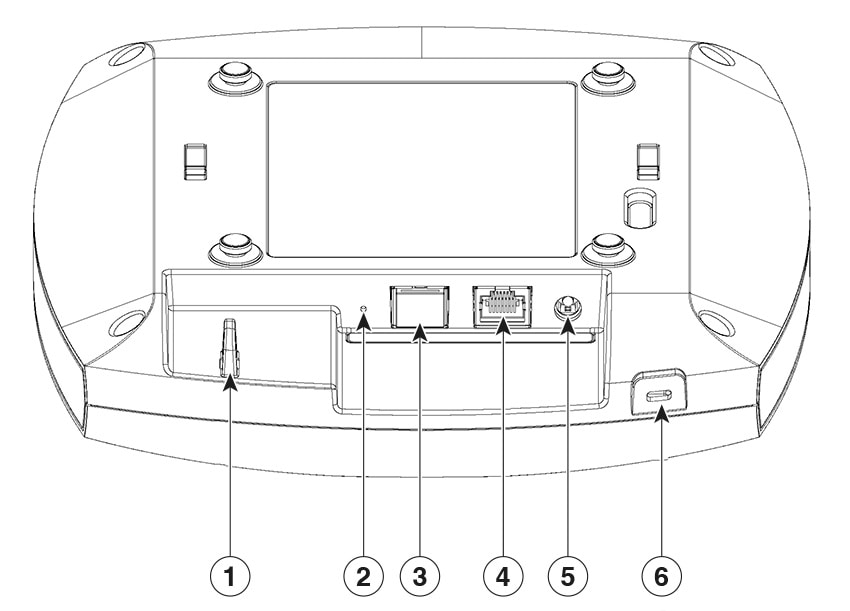
CW9174I top view

Figure 2. CW9174I top view with connectors and ports

1

Security hasp for padlocking AP to mounting bracket

4

Ethernet port 0

2

Reset button

For information about how to use the Reset button, see the Using the reset button section

5

DC jack

3

RJ-45 console port

Default baud rate is 115200.

6

Kensington lock slot

Checking the access point LEDs

The location of the access point status LED is shown in Connectors and ports on the AP.


Note


  • Regarding LED status colors, it is expected that there might be small variations in color intensity and hue from unit to unit. This is within the normal range of the LED manufacturer’s specifications and is not a defect. However, the intensity of the LED can be changed through the controller.

  • When the AP is in Meraki management mode, the LED status indicators convey the status differently from the Cisco APs.


The access point status LED indicates various conditions, which are described in the following table.

Table 1. LED status indications

Message Type

LED State

Message Meaning

Association status

Green

Normal operating condition, but no wireless client is associated

Blue

Normal operating condition, at least one wireless client is associated

Boot loader status

Green

Executing boot loader

Boot loader error

Blinking Green

Boot loader signing verification failure

Operating status

Blinking Blue

Software upgrade in progress

Alternating between Green and Red

Discovery or join process in progress

Access point operating system errors

Cycling through Red-Off-Green-Off-Blue-Off

General warning; insufficient inline power

Top right ethernet LED

Off

Link speed is 10 Mb, 100 Mb, or disconnected

Orange

Link speed is 1000 Mb

Green

Link speed is 2.5 Gb, 5 Gb, or 10 Gb

Top left ethernet LED

Blinking Green

Activity indicator for received signal or transmitted signal

Table 2. LED status indications for Meraki

Message type

LED state

Message meaning

Boot status

Orange

AP is booting (permanent Orange suggests hardware issue)

Initialization status

Rainbow

AP is initializing/scanning

Upgrade status

Blinking Blue

AP is upgrading

Gateway mode (no clients)

Green

AP in Gateway mode with no clients

Gateway mode (with clients)

Blue

AP in Gateway mode with clients

Uplink status

Blinking Orange

AP can't find uplink