Servicing the Node
The Cisco 8200 Secure Router Node contains components that can be serviced after the node is removed from the Cisco UCS XE9305 chassis. The sheet-metal top cover protects the internal components and maintains the airflow path. Remove the cover only when servicing an internal component, and reinstall the cover before returning the node to service.
The procedures in this chapter cover the top cover, the internal M.2 card, and the system battery. The Power over Ethernet (PoE) daughter board is removed temporarily to access the battery.
 Important |
Only trained personnel should remove the router node or service its internal components. |
Serviceable Component Locations
The following components are covered by the service procedures in this chapter.
|
Component |
Location |
Access |
Tool |
|---|---|---|---|
|
Top cover |
Top of router node |
Release button and retention pins |
No tool required |
|
M.2 card |
Internal motherboard |
Remove top cover |
#1 Phillips; retaining screw: 2.8–3.7 in-lb |
|
System battery |
Below the PoE daughter board |
Remove top cover and PoE daughter board |
#1 Phillips; PoE-board screws: 2.8–3.7 in-lb |
Pre-Installation Requirements and Considerations
Site Preparation Requirements
Before installing the router node, be aware of the following:
-
Power Infrastructure: Ensure the Cisco UCS XE9305 Chassis is properly connected to a stable power source compatible with the 12 to 54 VDC input requirements. Verify that the total PoE power budget (up to 360W) is accounted for in your power planning.
-
Grounding: The Cisco UCS XE9305 Chassis must be properly grounded to prevent electrostatic discharge (ESD) damage to the high-density ARM v9 SOC and FPGA components.
Installation Caveats and Considerations
Datacenter administrators should be aware of the following operational considerations:
-
Hot-Swap: The Cisco 8200 Secure Router Node supports hot-swap functionality. However, ensure the host chassis is powered and stable before engaging the node.
-
ESD Precautions: When you handle the router node, especially when the top cover is removed and the motherboard, PoE daughter card, and their components are accessible, always wear an ESD-preventive wrist strap during installation or removal.
Component Replacement Warnings
For component replacement, be aware of the following.
Note |
An instructed person is someone who has been instructed and trained by a skilled person and takes the necessary precautions when working with equipment. A skilled person or qualified personnel is someone who has training or experience in the equipment technology and understands potential hazards when working with equipment. |
 Warning |
Only an instructed person or skilled person should be allowed to install, replace, or service this equipment. See statement 1089 for the definition of an instructed person or skilled person. |
Removing the Router Node Top Cover
Each Cisco 8200 Secure Router Node in the chassis has a sheet metal top cover to protect components and provide optimal airflow. The top cover must be removed to access any field-serviceable components.
The top cover is held in place by the following features.
-
Release button that locks and unlocks the latch for the top cover.
-
Retention pins that insert into grooves on the top of the node.
Use this procedure to remove the top cover before servicing an internal component.
Before you begin
-
Shut down the router node, disconnect all cables, and remove the node from the chassis. See Removing a Router Node.
-
Place the router node top-side up on a grounded, static-safe work surface.
Procedure
|
Step 1 |
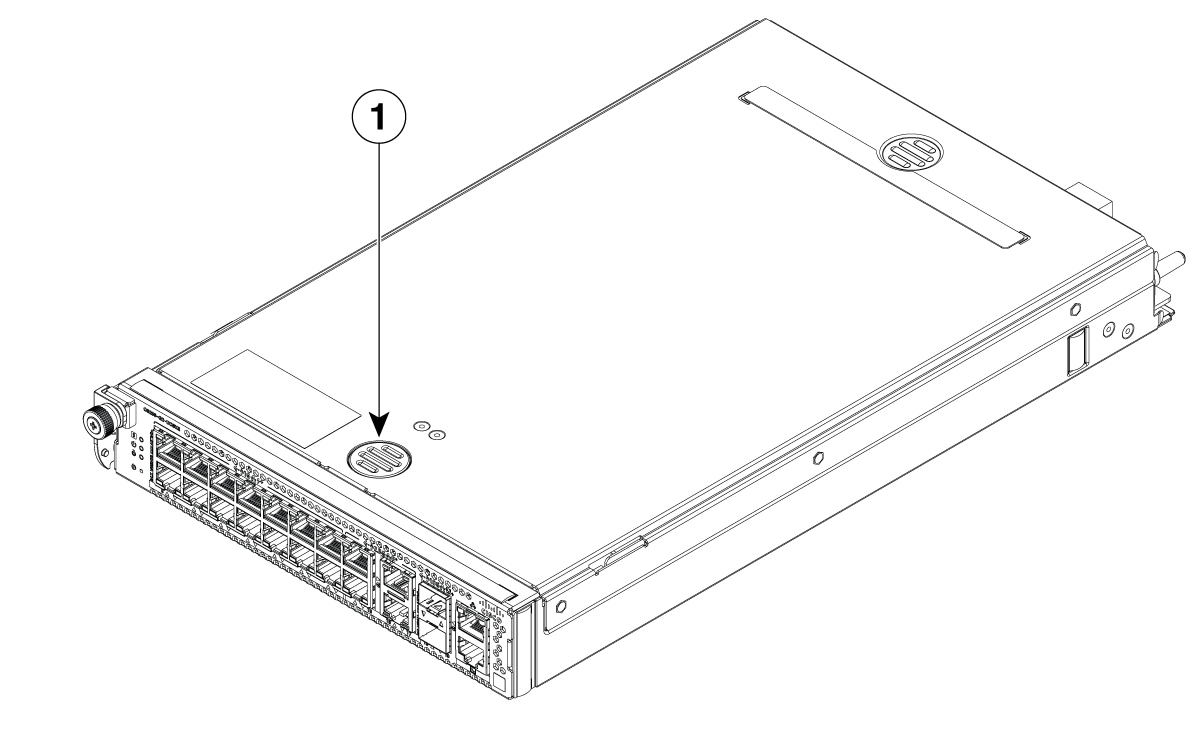
Press the top-cover release button to disengage the cover latch.
|
|
Step 2 |
While holding the release button down, slide the cover toward the back of the node. |
|
Step 3 |
Lift the back end of the cover until the retention pins clear the chassis grooves, then remove the cover. |
Installing the Router Node Top Cover
Install the router node's top cover after all service procedures are complete and before re-installing the router node into the chassis. The top cover must be installed to ensure optimal airflow and protect the Cisco 8200 Secure Router Node's internal components.
Use this procedure to install the router node's top cover after performing maintenance or replacing field-serviceable components.
Before you begin
Be aware that when the router node is re-installed, it will power on after successfully connecting to the power backplane.
Procedure
|
Step 1 |
Align the retention pins on the top cover with the corresponding grooves on the top of the node. |
|
Step 2 |
Lower the cover onto the node and ensure that the retention pins are seated correctly in the grooves. |
|
Step 3 |
Slide the cover toward the front of the node while guiding the leading edge under the sheet-metal lip above the faceplate. |
|
Step 4 |
Continue sliding the cover until the release button clicks and the cover locks into place. Gently try to slide the cover backward to verify that it is secure. The router node powers on after it is fully inserted into the chassis and connects to the power backplane. |
What to do next
Choose the appropriate option:
-
If you will return the router node to service, insert it back into the chassis and connect cables.
Go to Installing a Router Node.
-
If you will not install any node in the slot previously occupied by the router node, install a blank filler panel.
Removing the M.2 Card
Use this procedure to remove the M.2 card from the router node.
Before you begin
-
Remove the router node from the chassis and place it on a grounded, static-safe work surface.
-
Gather a #1 Phillips screwdriver and an ESD-safe container for the M.2 card.
Procedure
|
Step 1 |
Remove the top cover. See Removing the Router Node Top Cover. |
|
Step 2 |
Locate the M.2 card and its retaining screw. |
|
Step 3 |
Loosen and remove the retaining screw with the #1 Phillips screwdriver. Keep the screw for installation. 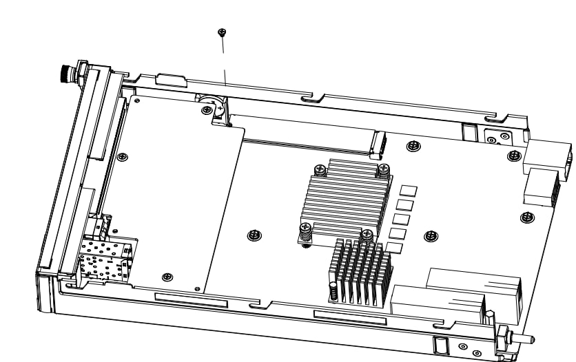 |
|
Step 4 |
Lift the free end of the M.2 card slightly, slide the card out of the motherboard connector, and place it in an ESD-safe container. 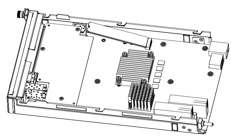 |
What to do next
Install the replacement M.2 card. See Installing the M.2 Card.
Installing the M.2 Card
Use this procedure to install an M.2 card in the router node.
Before you begin
-
Verify that the replacement M.2 card is supported for the router node.
-
Inspect the motherboard connector and retaining screw location for damage or debris.
Procedure
|
Step 1 |
Align the keyed edge connector on the M.2 card with the motherboard connector. |
|
Step 2 |
Insert the card into the connector at a slight angle until it is fully seated. |
|
Step 3 |
Lower the free end of the card to the retaining point. 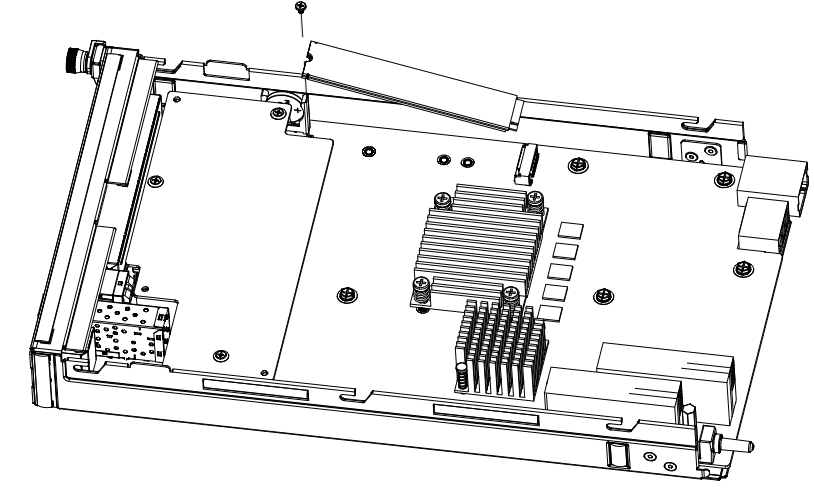 |
|
Step 4 |
Install the retaining screw with the #1 Phillips screwdriver and tighten it to 2.8–3.7 in-lb (0.32–0.42 N·m). |
|
Step 5 |
Install the top cover. See Installing the Router Node Top Cover. 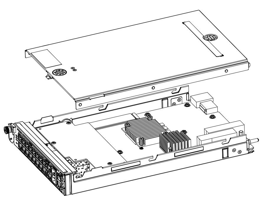 |
|
Step 6 |
Return the router node to service. Install it in the chassis, reconnect the cables, and verify normal boot and status-LED operation. |
Removing the Battery
The router node has an internal coin-cell battery beneath the PoE daughter board. The PoE daughter board must be removed temporarily to access the battery.
Warning |
Use only the manufacturer-approved replacement battery. Installing an incorrect battery type or installing the battery with reversed polarity can create a risk of fire, explosion, or leakage. |
Use this procedure to remove the battery from the router node.
Before you begin
-
Shut down the router node.
-
Remove the router node from the chassis and place it on a grounded, static-safe work surface.
-
Gather a #1 Phillips screwdriver and the approved replacement battery.
Procedure
|
Step 1 |
Remove the top cover. See Removing the Router Node Top Cover. |
|
Step 2 |
Locate the PoE daughter board that covers the battery area. |
|
Step 3 |
Loosen and remove the PoE-board securing screws with the #1 Phillips screwdriver. Retain the screws. 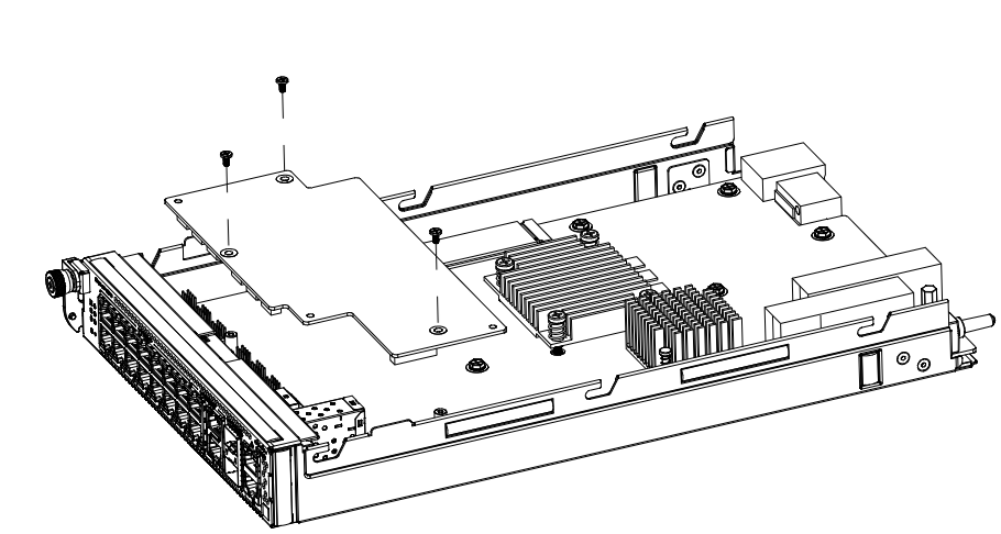 |
|
Step 4 |
Lift the PoE daughter board from the node and place it on an ESD-safe surface. |
|
Step 5 |
Note the battery polarity and its orientation in the holder. |
|
Step 6 |
Release the battery from the holder with your fingers and remove it. Do not use a sharp or conductive tool. 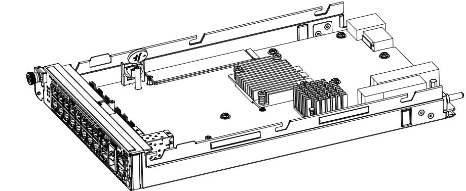 |
What to do next
Install the replacement battery. See Installing the Battery.
Installing the Battery
Use this procedure to install the replacement battery and reassemble the router node.
Before you begin
-
Confirm that the replacement battery type is approved for the router node.
-
Confirm the polarity and orientation recorded during removal.
Procedure
|
Step 1 |
Insert the replacement battery into the holder in the same orientation as the removed battery. Press until the battery is fully retained. |
|
Step 2 |
Position the PoE daughter board over its connectors, alignment features, and screw holes, then lower it evenly into place. |
|
Step 3 |
Install the PoE-board securing screws with the #1 Phillips screwdriver and tighten them to 2.8–3.7 in-lb (0.32–0.42 N·m). 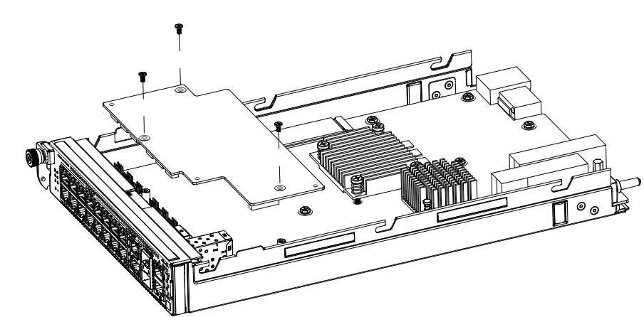 |
|
Step 4 |
Install the top cover. See Installing the Router Node Top Cover. |
|
Step 5 |
Return the router node to service. Install it in the chassis, reconnect the cables, and verify normal boot and status-LED operation. |
 Feedback
