Cisco 8200 Secure Router Node Overview
The Cisco 8200 Secure Router Node (router node) is a single-slot routing and switching node for the Cisco Unified Edge computing platform.
Supported in the Cisco UCS XE9305, the router node features different Gigabit Ethernet and multi-Gigabit Ethernet (mGig) ports to provide Local Area Networking and Software Defined Wide Area Networking (SD-WAN) functionality for the Cisco Unified Edge solution.
Zero, one, or two router nodes are supported in each Cisco UCS XE9305 chassis. If zero router nodes are installed, network connectivity must occur through another option, such as the uplink ports on the eCMC modules.
-
Fourteen (14) individual 1Gbps ports through an RJ-45 connector. Each port carries traffic over CAT5 copper cables on the local area network. Each of these ports supports power through 30W PoE+.
-
Four (4) individual 2.5Gbps mGig ports through an RJ-45 connector. Each port carries traffic on CAT6A copper cables on either the LAN or Software Defined Wide Area Network (SD-WAN). Each of these ports supports power through 90W UPoE+.
-
Two (2) individual 10Gbps ports through SFP ports. Each port carries LAN/WAN traffic over a copper cable.
-
One 1Gbps Console port through an RS232 port. This port handles the local console connection over a CAT5 copper cable.
-
One 10/100/1000Gbps Management port through an RJ-45 port. This port handles the out-of-band management traffic over a CAT5 copper cable.
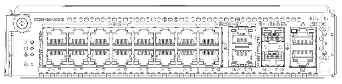
For additional information about the Cisco UCS XE9305 chassis that hosts the router node, see the Cisco UCS XE9305 Chassis Installation and Service Guide.
Router Node Front Panel
The Cisco 8200 Secure Router Node is installed into the Cisco UCS XE9305 Chassis from the front of the chassis. All routing/switching features are easily accessible from the front of the node. The rear of the node inserts into the chassis and contains the connections to the chassis data and management planes.
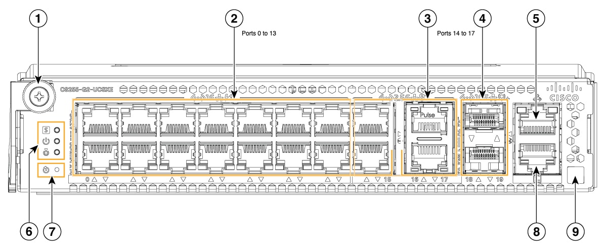
The router node front panel contains the following features.
|
Callout Number |
Component Description |
|---|---|
|
1 |
Captive thumbscrew Supports securing the node into, or removing it from, the chassis slot by using either your fingers or a #2 Phillips screwdriver. |
|
2 |
1G Ethernet Ports, Fourteen (Port 0 to Port 13) Supports 1 Gbps network connectivity through RJ-45 ports and CAT5 copper cables. |
|
3 |
2.5G Ethernet Ports, Four (Port 14 - Port 17) Supports high-speed 2.5 Gbps LAN or WAN connectivity through RJ-45 ports and CAT6 copper cables. |
|
4 |
SFP+ Ports, Two (Port 18 and Port 19) Supports high-speed connectivity through SFP+ transceiver modules and copper or fiber cables. |
|
5 |
Management Port, One (Port 20) Supports a dedicated RJ-45 port over a CAT5 copper cable for out-of-band management. |
|
6 |
Node Status LEDs Indicators for Power, System Health, and Beacon (Locator) status. |
|
7 |
Reset Button, One |
|
8 |
Console Port, One (Port 21) Supports a serial interface for local management and troubleshooting. |
|
9 |
Node Identification Label Supports a QR code for each node's specific information. |
Router Node Identification
Each Cisco 8200 Secure Router Node features a node identification tag at the lower-right corner of the node's faceplate.
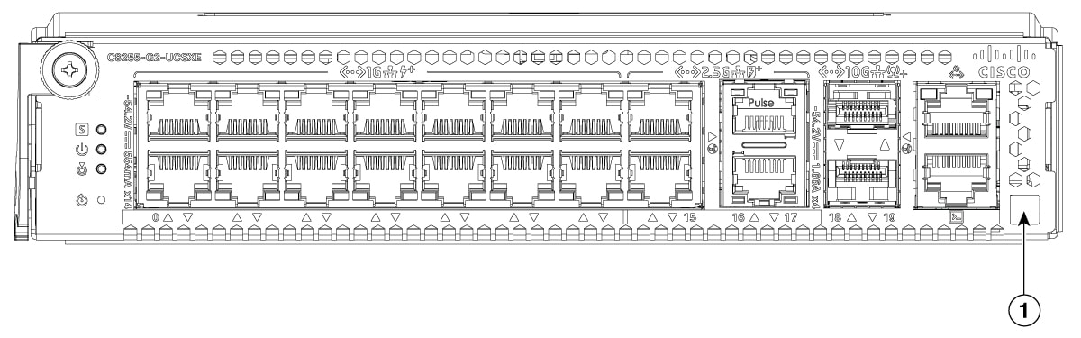
The node identification tag (denoted as 1 in the image) is a QR code that contains information that uniquely identifies the product, such as:
-
The Cisco product identifier (PID) or virtual identifier (VID)
-
The product serial number
The product identification tag applies to the entire router node. Additional information, such as PIDs or serial numbers might be applied to individual components.
You will find it helpful to scan the QR code so that the information is available if you need to contact Cisco personnel.
Node Status LEDs
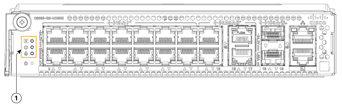
The Cisco 8200 Secure Router Node has an LED cluster that displays various operational and performance states. The LEDs are for the overall node.
 Note |
Status LEDs for individual ports are also available. For more information, see Port LEDs. |
|
LED Icon |
LED Color |
Status |
|---|---|---|
|
System Status |
Off |
No power |
|
Red |
Blinking: Hardware integrity error |
|
|
Orange |
|
|
|
Green |
Steady: Normal system operation, IOS is loaded |
|
|
White |
|
|
|
Power OK Status |
Off |
No -53.5V POE power |
|
Green |
Steady: -53.5V POE power connected and all powered ports are operating normally |
|
|
Amber |
Steady: -53.5V POE power connected, but one or more POE ports have a fault |
|
|
Beacon/Locator |
Off |
Beacon not activated |
|
Blue |
Blinking: Beacon activated |
Port Numbering
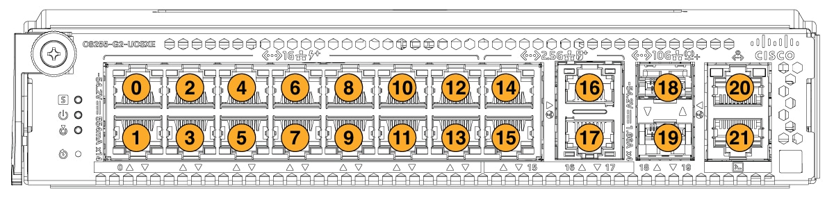
Ports on the Cisco 8200 Secure Router Node are numbered sequentially, top-down and left to right starting with port zero (0) at the top left corner of the node. Port numbers are silk screened onto the faceplate for easy identification.
The following image shows the port numbering for the router node.
|
Port Number |
Port Function |
|---|---|
|
0-13 |
1G Ethernet LAN Ports |
|
14-17 |
2.5G Ethernet LAN/WAN Ports |
|
18-19 |
SFP+ Ports |
|
20 |
Management Port |
|
21 |
Console Port |
Gigabit Ethernet Ports
Overview
The Cisco 8200 Secure Router Node features fourteen (14) Gigabit Ethernet (1GE) copper ports designed for LAN connectivity. These ports provide high-density access for local network infrastructure.
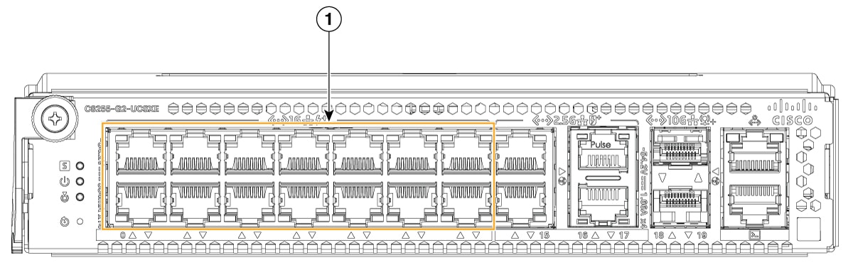
Physical Interface and Cabling
The 1GE LAN ports utilize standard RJ-45 connectors and support the following physical requirements:
-
Cabling: Standard copper Ethernet cabling (CAT5 or higher) is required for connectivity.
-
PHY Technology: Connectivity is managed by two Marvell 88E1780 Ethernet PHY devices, each supporting eight ports.
-
Power over Ethernet (PoE): Each of the 14 GE LAN ports is capable of providing up to 30W of PoE+ power (802.3at, 2-pair PSE), allowing the node to power connected peer devices.
Typical Usage
The 1GE LAN ports are dedicated to LAN-side connectivity and are distinct from the Multi-Gigabit WAN or SFP+ interfaces. Typical roles include:
-
LAN Downlinks: Providing network access to end-user devices, including workstations, printers, and other local endpoints within a corporate or branch environment.
-
Internal Network Segments: Facilitating traffic within internal corporate intranets or private local clusters.
-
Peer Device Connectivity: Supporting east-west traffic between local network devices that do not require the higher bandwidth of the 2.5G or SFP+ interfaces.
Note |
The 1GE LAN ports are not intended for primary public cloud or WAN uplink traffic. These types of traffic are handled by the router node's dedicated Multi-Gigabit WAN and SFP+ interfaces. |
Multi-Gigabit Ethernet Ports
Overview
The Cisco 8200 Secure Router Node provides four (4) 2.5 Gbps Multi-Gigabit (mGig) Ethernet WAN ports. These ports deliver high-bandwidth, flexible WAN connectivity for modern enterprise edge deployments.
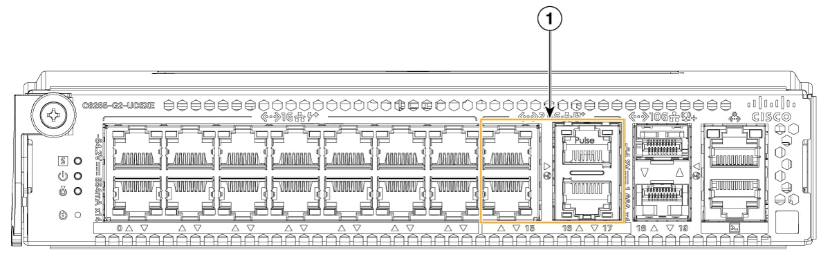
Physical Interface and Cabling
The mGig WAN ports utilize RJ-45 connectors and are engineered for high-performance data transmission over copper media:
-
Cabling: Supports Category 5e (CAT5e) or higher copper cabling for cable routes up to 100 meters on CAT5e for 2.5G and 5G modes. However, CAT6 copper is recommended.
-
Media Type: These ports support copper UTP cabling only. Fiber optic connectivity is not supported on these interfaces; fiber requirements are handled by the dedicated SFP+ ports on the node.
-
Data Rates: The ports are IEEE 802.3bz/NBASE-T compliant, supporting auto-negotiated data rates of 10 Mbps, 100 Mbps, 1 Gbps, and 2.5 Gbps.
-
Power over Ethernet (PoE): Each of the four mGig ports supports 802.3bt UPOE+ (Type 4), capable of delivering up to 90W of power per port.
Each of 1 Gbps port supports 802.3 at (PoE+) standard (Type 2).
Total POE power available is 360W.
Typical Usage
The mGig ports are optimized for WAN-side uplinks and high-bandwidth service delivery. Typical deployment roles include:
-
WAN Uplinks: Connecting to high-speed broadband services, including cable, fiber-to-the-premises (FTTP), or other carrier-grade ethernet services that exceed standard 1 Gbps limitations.
-
Public/Private Cloud Access: Providing the necessary throughput for latency-sensitive applications requiring access to public cloud resources or private data centers.
-
High-Bandwidth Branch Connectivity: Serving as the primary uplink for branch offices that require multi-gigabit throughput to handle increased traffic from cloud-based SaaS applications and unified communications.
SFP Plus Ports
SFP+ Ports Overview
The Cisco 8200 Secure Router Node features two (2) high-speed SFP+ ports, designated as SFP0 and SFP1. These ports provide flexible, high-bandwidth connectivity for fiber or copper transceiver modules, supporting 10 Gbps data rates.
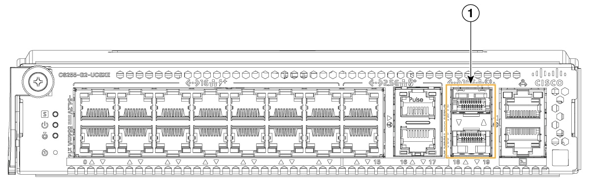
Physical Interface and Power
The SFP+ ports have the following power and signaling characteristic.
-
Power Delivery: Each SFP+ socket is capable of providing up to 2.5W of power at 3.3V, supporting a wide range of optical and copper transceiver modules.
Typical Usage
The SFP+ ports are intended for high-speed uplink or interconnect scenarios.
-
Fiber Uplinks: Connecting to high-speed fiber-optic WAN services or long-distance inter-switch links using 10GBASE-SR, 10GBASE-LR, or 10GBASE-ER transceivers.
-
High-Speed Interconnects: Providing 10 Gbps connectivity to core network switches or aggregation devices within the data center or enterprise campus.
-
Future-Proofing: The power and signal specifications allow for the potential support of specialized modules, such as XGPON or DSL SFPs, depending on software and transceiver qualification.
Management and Console Ports
Overview
The Cisco 8200 Secure Router Node includes a dedicated Management port and Console port for direct connection to the router node.
Management (MGMT) Port
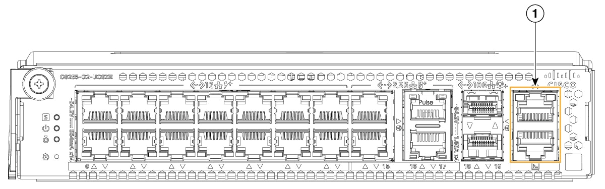
The Cisco 8200 Secure Router Node includes a dedicated Ethernet management port. This port is designed for out-of-band (OOB) management, allowing administrators to access and configure the device independently of the data plane traffic.
-
Connectivity: Supports 10/100/1000 Mbps auto-negotiation through a standard RJ-45 copper interface over a CAT5 cable.
-
Management Features: Supports a comprehensive suite of management tools, including Express Setup, Network Assistant, Secure Shell (SSH), Telnet, TFTP, SNMP, and DHCP-based auto-configuration.
-
Protocol Support: Fully compliant with IPv4/IPv6 stacks, Cisco Discovery Protocol, and DHCP relay agent functionality.
-
Isolation: The management port is logically isolated from the network data ports; it does not support routing packets from the management interface to the network ports, ensuring secure administrative access.
Console (CONSOLE) Port
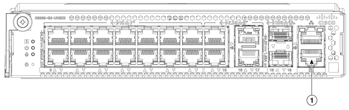
The router node features a console port that provides a direct serial interface for local management, troubleshooting, and initial system bring-up. The CONSOLE port utilizes a standard Cisco RS-232 RJ-45 interface over a CAT5 copper cable.
-
Physical Interface: Uses a standard RJ-45 jack with Cisco-defined RS-232 pinout (TXD, RXD, CTS, and RTS).
-
Connectivity: The port is connected to the Host SOC via a 4-pin UART interface.
-
Usage: Intended for direct local access by technicians to the Command Line Interface (CLI), providing a reliable path for system recovery and low-level diagnostic monitoring.
Port LEDs
Gigabit Ethernet Port LEDs
1GE Port LED Indicators
Each 1GE Ethernet port is equipped with two integrated LEDs that provide real-time operation and performance status for the port. The LEDs are at the top left and top right corners of the port.
-
The left LED provides a visual indication of the presence of transmit and receive network traffic that is ingressing or egressing the port.
-
The right LED provides a visual indication of the physical link status and alerts the user to any Power over Ethernet (PoE) faults.
|
LED Type |
LED Color Codes |
|---|---|
|
Left LED (Activity) |
|
|
Right LED (Link / POE Fault) |
|
Multi-Gigabit Ethernet Port LEDs
Multi-Gigabit Ethernet Port LED Indicators
Each Multi-Gigabit Ethernet (mGig) port is equipped with two integrated LEDs that provide real-time operation and performance status for the port. The LEDs are at the top left and top right corners of the port.
-
The left LED provides a visual indication of the presence of transmit and receive network traffic that is ingressing or egressing the port.
-
The right LED provides a visual indication of the physical link status and alerts the user to any Power over Ethernet (PoE) faults.
|
LED Type |
LED Color Codes |
|---|---|
|
Left LED (Activity) |
|
|
Right LED (Link / POE Fault) |
|
SFP Plus Port LEDs
The Cisco UCS XE9305 SDWAN SLED features two (2) high-speed SFP+ ports, designated as SFP0 and SFP1. These ports are designed for flexible, high-bandwidth uplink or interconnect scenarios, supporting 10 Gbps data rates for fiber or copper transceiver modules.
Each SFP+ port is equipped with one dedicated status LED to provide a visual indication of link integrity and SFP+ transceiver health.
|
LED Type |
LED Color Codes |
|---|---|
|
Link / Fault Status |
|
Management and Console Port LEDs
Management Port LED
The dedicated Ethernet management port is an RJ-45 port that supports administrative access for tasks such as local management and firmware updates. The port features two integrated LEDs located at the top left and right corners of the port.
The LEDs provide visual indicators of performance and operational status of out-of-band (OOB) network management traffic that is isolated from typical network traffic.
|
LED Type |
LED Color Codes |
|---|---|
|
Left LED (Activity) |
|
|
Right LED (Link) |
|
Console Port LED
The Console port is a passive serial (RS-232) interface to the router node. The Console port has no status LED.
Node Reset Button
Reset Button
The Cisco 8200 Secure Router Node features a recessed, pin-hole Reset button on the node's faceplate. The Reset button is located on the node's faceplate below the Beacon or Locator LED.
Because the Reset button is recessed, this design feature prevents the node from being reset unintentionally. To activate the Reset button, you must use a small tool, for example, a paper clip to press the switch and cause the reset.
After pressing the Reset button, the node will perform a warm restart, in which main power is maintained to the node.
 Feedback
