Cisco UCS Director
Cisco UCS Director is a complete, highly secure, end-to-end management, orchestration, and automation solution for a wide array of Cisco and non-Cisco data infrastructure components, and for the industry's leading converged infrastructure solutions based on the Cisco UCS and Cisco Nexus platforms. For a complete list of supported infrastructure components and solutions, see the Cisco UCS Director Compatibility Matrix.
Cisco UCS Director is a 64-bit appliance that uses the following standard templates:
-
Open Virtualization Format (OVF) and Open Virtual Appliance (OVA) for VMware vSphere
-
Virtual Hard Disk (VHD) for Microsoft Hyper-V
Management through Cisco UCS Director
Cisco UCS Director extends the unification of computing and networking layers through Cisco UCS to provide you with comprehensive visibility and management of your data center infrastructure components. You can use Cisco UCS Director to configure, administer, and monitor supported Cisco and non-Cisco components. The tasks you can perform include the following:
-
Create, clone, and deploy service profiles and templates for all Cisco UCS servers and compute applications.
-
Monitor organizational usage, trends, and capacity across a converged infrastructure on a continuous basis. For example, you can view heat maps that show virtual machine (VM) utilization across all your data centers.
-
Deploy and add capacity to converged infrastructures in a consistent, repeatable manner.
-
Manage, monitor, and report on data center components, such as Cisco UCS domains or Cisco Nexus network devices.
-
Extend virtual service catalogs to include services for your physical infrastructure.
-
Manage secure multi-tenant environments to accommodate virtualized workloads that run with non-virtualized workloads.
Automation and Orchestration with Cisco UCS Director
Cisco UCS Director enables you to build workflows that provide automation services, and to publish the workflows and extend their services to your users on demand. You can collaborate with other experts in your company to quickly and easily create policies. You can build Cisco UCS Director workflows to automate simple or complex provisioning and configuration processes.
Once built and validated, these workflows perform the same way every time, no matter who runs the workflows. An experienced data center administrator can run them, or you can implement role-based access control to enable your users and customers to run the workflows on a self-service basis, as needed.
With Cisco UCS Director, you can automate a wide array of tasks and use cases across a wide variety of supported Cisco and non-Cisco hardware and software data center components. A few examples of the use cases that you can automate include, but are not limited to:
-
VM provisioning and lifecycle management
-
Network resource configuration and lifecycle management
-
Storage resource configuration and lifecycle management
-
Tenant onboarding and infrastructure configuration
-
Application infrastructure provisioning
-
Self-service catalogs and VM provisioning
-
Bare metal server provisioning, including installation of an operating system
Features and Benefits
The features and benefits of Cisco UCS Director are as follows:
| Feature | Benefit |
|---|---|
|
Central management |
|
|
Self-service catalog |
|
|
Adaptive provisioning |
|
|
Dynamic capacity management |
|
|
Multiple hypervisor support |
|
|
Computing management |
|
|
Network management |
|
|
Storage management |
|
Physical and Virtual Management Features
|
Physical Server Management
|
Virtual Computing Management
|
|
Physical Storage Management
|
Virtual Storage Management
|
|
Physical Network Management
|
Virtual Network Management
|
Model-Based Orchestration
Cisco UCS Director includes a task library containing over 1000 tasks and out-of-the-box workflows. Model-based orchestration and a workflow designer enable you to customize and automate the infrastructure administrative and operational tasks. You can extend and customize the system to meet individual needs.
The following table shows the maintenance and update activities of the task library from day1 through day 3:
| Day-1 | Day-2 | Day-3 |
|---|---|---|
|
|
|
User Interface of Cisco UCS Director
Cisco UCS Director introduces a new user interface for the administrative portal. This section introduces you to some of the key features of this new user interface.
Change in Navigation
In earlier releases, you could access screens using the main menu bar. Starting with this release, all navigation options are now available from a side bar, and not from the horizontal main menu bar. As a result, the main menu bar is no longer visible in the user interface. You can use your mouse or the cursor to hover over an option on the side navigation bar, and then click on any of the menu options.
Absence of User Interface Labels
The user interface no longer includes labels for actions such as Add, Edit, Delete, Export, and Filter. These actions are represented only with icons. If you use your mouse or cursor to hover over the icon, the label will display the action you can perform using that icon. You can also modify the icons in the user interface for all actions and status messages. For more information, see Modifying an Icon in the Cisco UCS Director User Interface.
Using Dashboard to Access Detailed Reports
If you have enabled the Dashboard, then it is the first screen that you will see when you login to Cisco UCS Director. Typically, you can use this dashboard to add important or frequently accessed report widgets. Now, you can click on any of the reports that are displayed on the Dashboard, and immediately access the screen in the user interface where more detailed information is displayed.
For more information, see Enabling the Dashboard
In addition, you can create multiple dashboards and delete them when you no longer need them. For more information, see Creating Additional Dashboards and Deleting a Dashboard.
Enhanced Capabilities with Tabular Reports
Following are some of the enhanced capabilities with tabular reports available in the user interface:
-
Right-click to view additional options
After you select a row, if you right-click on your mouse, a list of options relevant to the row you selected are displayed.
-
Filter and Search
You can use a Filter option or a Search option with tabular reports in the Cisco UCS Director interface. On any page with a tabular report, you can use the Filter option that allows you to narrow down the tabular report results with a specific criteria. You can use this Filter option on tabular reports that do not span across pages. For tabular reports that do span across multiple pages, you can use the Search option to narrow down your search result.
-
Adding tabular reports to the Favorites menu
You can add any tabular report displayed in the user interface as a Favorite. By adding a report as a favorite, you can access this report from the Favorites menu.
-
Resizing of columns
You can resize all the columns that are displayed in the tabular report, including the last column. After you expand the columns, you can use the horizontal scroll bar to view the complete screen.
-
Informational message displayed in the absence of data
If there is no information to be displayed in a report, the following message is displayed.
No Data
Removing and Restoring Tabs
On any screen that has multiple tabs available, you can choose the number of tabs that you would like to see on that screen. If you close a tab on a screen, it will no longer be displayed in the row of tabs displayed in the user interface. If you would like to bring it back on the screen, then click the arrow facing downwards that is visible on the far right of the screen. It displays a drop-down list of tabs that are available but hidden from view. Choose the tab you would like to restore.
 Note |
You can remove and restore tabs on a screen only when there are a minimum of two tabs. This functionality is not available when there is only one tab displayed on a screen in the interface. |
Enhancements to Reporting Capabilities
Following are some of the enhanced reporting capabilities available in the user interface:
-
Introduction of pie charts and bar graphs
Each individual pie chart or bar graph can be exported out of the system in PDF, CSV or XLS format, or can be added to the Dashboard.
-
Availability of More Reports option
Using the More Reports option, you can now generate reports on specific data for the resources in the cloud accounts. For more information, see Generating Additional Reports for a Cloud Account.
Landing Page
The landing page opens when you log in to the Cisco UCS Director administrator portal. The elements that you see on the landing page depend upon how you have configured the display. By default, the Converged View is displayed when you login to the portal.
The following are the available elements for your landing page:
-
Header—Displays across the top of the screen.
-
Navigation menu—The main navigation bar is no longer on the top of the screen. It is now available as a vertical menu on the left-side of the screen.
Note |
The menu does not have a scroll bar. The menu only displays the number of options that fit in the space available. Some options may not appear if you minimize your screen or zoom in. You can click Site Map to view all available options. |
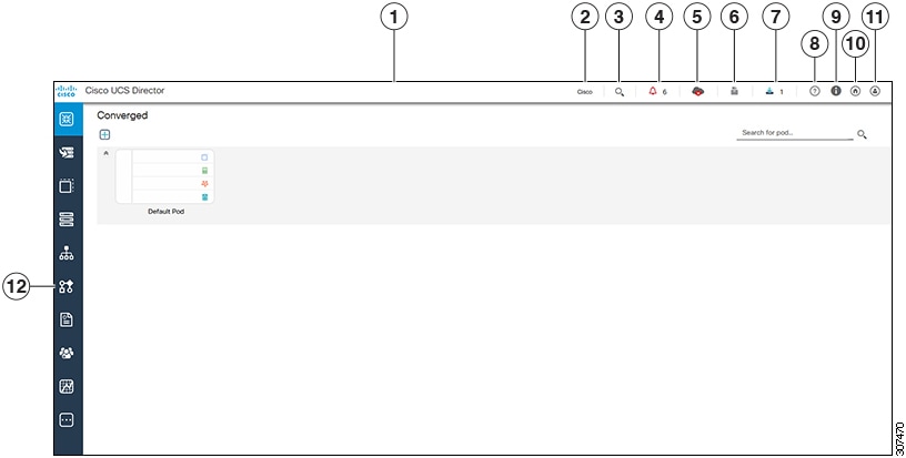
|
Number |
Name |
Description |
|---|---|---|
|
1 |
Header |
Contains frequently accessed elements, including the menu. The header is always visible. |
|
2 |
Link |
Provides a link to the Cisco website from where you can access information on using the software. |
|
3 |
Search icon |
Allows you to search for and navigate directly to a specific report in the portal. |
|
4 |
Diagnostic System Messages icon |
Displays the number of diagnostic system messages that have been logged. Clicking on this link takes you to the Diagnostic System Messages screen from where you can view detailed information. |
| 5 | Claim Status icon | Displays the claim status of the device in Cisco Intersight. |
|
6 |
Service Request Quick View Panel |
Launches the Service Request Quick View panel that displays the recent in-progress, completed and failed service requests. This feature is not available in Cisco UCS Director instances that have been cross-launched from Cisco Intersight. |
|
7 |
New Upgrade Notification |
Displays the list of connector packs available for upgrade. Clicking on this link takes you to the Available System Upgrades screen from where you can view detailed information. |
|
8 |
Help icon |
Links to the online help system for the administrator portal. |
|
9 |
About icon |
Displays information about the software, and the version that is currently installed. |
|
10 |
Home icon |
Returns you to the landing page from any location in the user interface. |
|
11 |
User icon |
Allows you to edit your profile, enable or disable the dashboard, and log out. |
|
12 |
Navigation menu |
The vertical navigation menu using which you can access different screens in the interface. |
Common Icons
The following table provides information about the common icons used in the user interface. You can see the name of an icon when you hover over it with your mouse. Some icons may have a different name, depending upon the context in which they're used.
|
Icon |
Name |
Description |
||
|---|---|---|---|---|
|
|
Search |
Search is available on the header and on individual screens. Click Search on the header to find a report in the user interface. Click Search on an individual screen to find one or more items in the report. |
||
|
|
Alert |
Alert is available on the header. Click Alert to view your diagnostic system messages. |
||
|
|
User |
User is available on the header. Click User to access your profile, or to log out of the user interface. |
||
|
|
Export |
Export is available on individual screens. Click Export to export the content of the report that is visible on the screen. |
||
|
Import |
Import is available on individual screens. Click Import to import a file. |
|||
|
|
Refresh |
Refresh is available on individual screens. Click Refresh to refresh the data that is visible on the screen. |
||
|
|
View Details |
View Details is available on individual screens. Click View Details to see details about the selected row in the table. |
||
|
|
Table View |
Table view is available for your application containers and catalogs. Click Table View to view your application containers or catalogs in a table with details about each application container or catalog displayed. |
||
|
|
Tile View |
Tile view is available for your catalogs and application containers. Tile View to view your catalogs and application containers in a tiled view of icons. With this view, you must click on an icon to see details about that catalog item or application container. |
||
|
|
Create |
Create is available on individual screens. Click Create to create a new object, such as a VM disk. |
||
|
|
Add |
Add is available on individual screens. Click Add to add an item to an existing object, such as adding a catalog item to an existing catalog folder. The name of this icon may also include the item that you want to add, such as Add Catalog. |
||
 |
Expand a list of values |
Lists of values are available in forms when you must select one (single select) or more (multi select) items, for example IP addresses or VMs.
The item label appears to the right of the Expand icon. Click the Expand icon to display the list, then select an item or items. Once an item is selected, its value appears in parentheses to the right of the Expand icon and label. |
||
|
Collapse a list of values |
Once a list of values is expanded, the Expand icon changes to a Collapse icon. Click the Collapse icon to hide the list of values, for example to see what is beneath the list. |
|||
|
|
Edit |
Edit is available on individual screens. Click Edit to modify an existing object, such as a catalog item or a VM disk. |
||
|
|
Delete |
Delete is available on individual screens. Click Delete to delete an object, such as a catalog item or a VM disk. |
||
|
|
Custom Actions |
This icon represents additional tasks that do not have an associated icon. It also represents the default icon available in the user interface. |
||
|
Favorites |
Adds a page to the Favorites menu. You can use this option to view frequently accessed pages more quickly. |
|||
|
|
Filter |
Provides filtering parameters on the page. |
Note |
You can view the complete list of icons and the details from the screen. These icons are listed in the Action Icon Set category. |
Converged View
When you login to the administrator portal for the first time, by default, the Converged screen is displayed. This screen displays the currently configured pods in your environment. From this screen, you can add additional pods, or you can select a pod and view additional details on the resources within the pod. Typically, the additional details displayed include the following:
-
Virtual resources
-
Compute resources
-
Network resources
-
Storage resources
You can click on any of these resources, and the screen loads additional information.
Cisco UCS Director allows you to configure the Dashboard as the first screen to be displayed when you login to the user interface. For more information, see Enabling the Dashboard.
Generating Additional Reports for a Cloud Account
You can use the More Reports option to generate specific reports for either a virtual cloud account or for a physical pod account. The type of reports that are generated using this More Reports option varies based on the type of account.
If there is no information available to generate this report, then a message stating that there is no data is displayed.
Procedure
|
Step 1 |
Navigate to the cloud account that you want to generate additional reports for. |
|
Step 2 |
From the More Actions drop-down menu, click More Reports. |
|
Step 3 |
From the Type drop-down list, and Report drop-down list, choose the type of report that you want to generate. The report is generated and displayed in the user interface. |
|
Step 4 |
(Optional) Click to choose the format in which you want the report to be exported in. |
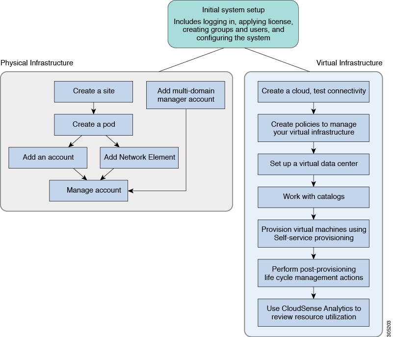
Guided Setup Wizards in Cisco UCS Director
Cisco UCS Director includes a set of wizards that guide you through configuring important features. The following are the available guided setup wizards:
-
Device Discovery—This wizard enables you to discover devices and assign them to a pod.
-
Initial System Configuration—This wizard helps you complete initial tasks to set up Cisco UCS Director, such as uploading licenses, and setting up SMTP, NTP, and DNS servers.
-
vDC Creation—This wizard enables you to configure the policies required to provision VMs in private clouds.
-
FlexPod Configuration—This wizard helps you set up a FlexPod account.
-
Vblock Pod Configuration—This wizard enables you to discover and assign accounts to Vblock pods.
-
VSPEX Pod Configuration—This wizard enables you to discover and assign accounts to VSPEX pods.
-
Virtual SAN Pod Configuration—This wizard enables you to set up a Virtual SAN Pod and add devices.
When you first log into Cisco UCS Director, a Wizard Explorer window is displayed. From this window, you can view the details of the available guided setup wizards and choose to launch any of them. If you do not want this Wizard Explorer to appear every time you log in, you can check the Do not show this page again checkbox. To launch these wizards later on, click .
In addition to these system-provided wizards, you can create a wizard from a workflow that you have previously configured. For more information, see Creating a Wizard from a Workflow.
Creating a Wizard from a Workflow
You can convert valid workflows into wizards, and save them in Cisco UCS Director.
Before you begin
You must have created valid workflows in Cisco UCS Director.
Procedure
|
Step 1 |
Choose . |
||||||||||||||
|
Step 2 |
On the Guided Setup page, click Setup. |
||||||||||||||
|
Step 3 |
From the More Actions drop-down menu, click Create from Workflow. |
||||||||||||||
|
Step 4 |
In the Create Wizard from Workflow screen, complete the required fields, including the following:
|
||||||||||||||
|
Step 5 |
Click Submit. |
What to do next
You can perform the following tasks:
-
Launch the wizard.
-
Edit the wizard.
-
View details of the wizard.
-
Re-order the wizard in the interface.
-
Delete the wizard.
 Feedback