Installation Notes and Warnings for the Cisco UCS 5108 Server Chassis
The following notes and warnings apply to all installation tasks:
 Note |
Before you install, operate, or service the system, see the Regulatory Compliance and Safety Information for Cisco UCS for important safety information. |
 Warning |
IMPORTANT SAFETY INSTRUCTIONS This warning symbol means danger. You are in a situation that could cause bodily injury. Before you work on any equipment, be aware of the hazards involved with electrical circuitry and be familiar with standard practices for preventing accidents. Use the statement number provided at the end of each warning to locate its translation in the translated safety warnings that accompanied this device. Statement 1071 SAVE THESE INSTRUCTIONS |
Warning |
This unit is intended for installation in restricted access areas. A restricted access area can be accessed only through the use of a special tool, lock and key, or other means of security. Statement 1017 |
Warning |
Only trained and qualified personnel must be allowed to install, replace, or service this equipment. Statement 1030 |
Rack Requirements
This section provides the requirements for installing in a standard open rack, assuming an external ambient air temperature range of 50 to 95°F (10 to 35°C):
Note |
Do not use racks that have obstructions. These obstructions could impair access to field-replaceable units (FRUs). |
The Cisco R Series Racks are an ideal choice. If other racks will be used, the rack must be of the following type:
-
Standard 19-inch (48.3 cm) four-post EIA rack, a minimum of 39.4 inches (100 cm) deep, with mounting rails that conform to English universal hole spacing per section 1 of ANSI/EIA-310-D-1992.
-
The mounting holes of the rails in the rack must be square (unless the optional round hole adapter kit is used).
-
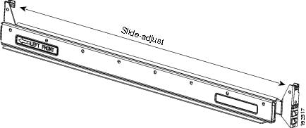
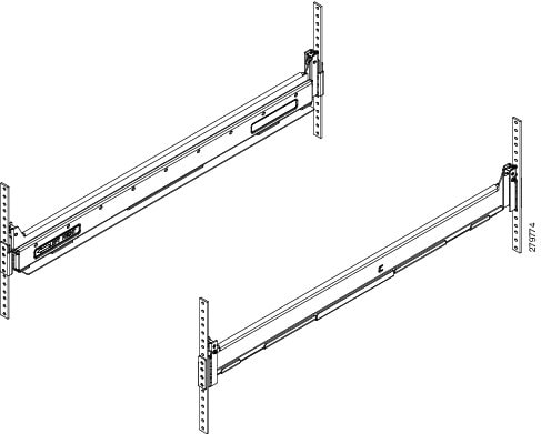
The tool-less rack-mount kit shipped with the chassis is required. The adjustable rack rails shipped with each enclosure extend from 29 inches (73.66 cm) to 35 inches (88.9 cm)
-
Front and rear doors—If your server rack includes closing front and rear doors, the doors must have 65 percent open perforated area evenly distributed from top to bottom to permit adequate airflow.

Caution
Always use blanking panels to fill all remaining empty front panel U-spaces in the rack. This arrangement ensures proper airflow. Using a rack without blanking panels results in improper cooling that can lead to thermal damage.
The rack must also meet the following requirements:
-
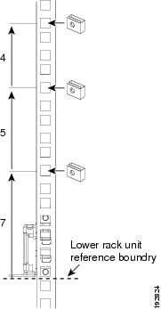
The minimum available vertical rack space per chassis must be six RU (rack units), equal to 10.5 inches (26.7 cm).
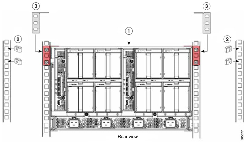
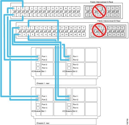
Cable Management
To help with cable management, allow additional space in the rack above and below the chassis to make it easier to route copper cables (plus up to eight copper cables per Cisco UCS 5108 server chassis) through the rack.
Cable management can be an important factor in preventing overheating issues. In the following figure, the “before“ illustration shows cables blocking the rear of the chassis, and preventing the fans from exhausting warm air from the chassis. This situation causes failed DIMMs in the blade servers, and seemingly random server shutdowns when internal temperatures exceed specification. Use cable ties and other wiring practices to keep the rear of the chassis unobstructed as shown in the “after“ illustration.

Airflow Considerations
Airflow through the chassis is from front to back. Air enters the chassis through the blade servers and power supply grills at the front of the chassis and exits through the fan modules on the back of the chassis. To ensure proper airflow, follow these guidelines:
-
Maintain ambient airflow throughout the data center to ensure normal operation.
-
Consider the heat dissipation of all equipment when determining air-conditioning requirements. Do not allow the exhaust of one system to be the intake for another system.
-
When evaluating airflow requirements, take into consideration that the hot air generated by equipment at the bottom of the rack can be drawn in the intake of the equipment above.
-
Make sure that the exhaust at the rear of the chassis is unobstructed for at least 24 in. (61 cm). This includes obstruction due to messy cabling practices.
-
Some blade servers ship with internal air baffles that are placed over the DIMMs and CPUs. They are used to channel airflow to where it is needed the most. The blades are designed to operate with air baffles installed and the system will not cool correctly if they are not installed.
-
If an enclosed rack is used, the front door must be 65 percent perforated to ensure adequate airflow to the servers.
Moving Server Chassis
When lifting the chassis, be aware of its weight, and follow these guidelines:
Caution |
Do not try to lift the chassis using the handles on the side. These handles are intended only for moving and adjusting the chassis position. |
-
Never lift the chassis alone—Always use two people to lift the chassis. If available, use a scissor jack or other lifting device designed for installing heavy equipment into data center racks.
-
Disconnect all power and external cables before lifting the chassis.
-
Remove all FEXes, power supplies, fans, and servers from the chassis before lifting.
-
Ensure that your footing is solid and the weight of the system is evenly distributed between your feet.
-
Lift the system slowly, keeping your back straight. Lift with your legs, not with your back. Bend at the knees, not at the waist.
Caution |
Do not remove the Power Distribution Unit (PDU) located at the back of the chassis. |
Installation Guidelines
When installing the chassis, follow these guidelines:
-
Plan your site configuration and prepare the site before installing the chassis. See Site Planning and Maintenance Records for the recommended site planning tasks. For details, see the Cisco UCS Site Preparation Guide.
-
Record the information listed in Site Planning and Maintenance Records as you install and configure the chassis.
-
Ensure that there is adequate space around the chassis to allow for servicing the chassis and for airflow.
-
Ensure that the air-conditioning meets the heat dissipation requirements listed in Technical Specifications
-
Ensure that the cabinet or rack meets the requirements listed in Rack Requirements.
Note
Jumper power cords are available for use in a rack. See Specifications for the Cisco UCS 5108 Blade Server Chassis Power Supply Units.
-
Ensure that the site power meets the power requirements listed in Technical Specifications. We recommend that you use a UPS to protect the UCS system. Using an unprotected supply exposes you to a risk of system failure due to input supply voltage variations or failures.
Avoid UPS types that use ferroresonant technology. These UPS types can become unstable with systems such as the Cisco UCS, which can have substantial current draw fluctuations due to fluctuating data traffic patterns.
-
Ensure that circuits are sized according to local and national codes. For North America, the power supply requires a 20 A circuit.
To prevent loss of input power, ensure that the total maximum loads on the circuits supplying power to the chassis are within the current ratings for the wiring and breakers.
-
Use the following torque values when installing the chassis:
-
10-32 screws: 20 in-lb
-
Required Equipment
Before you begin the installation, ensure that you have the following items:
-
Number 1 and number 2 Phillips-head screwdrivers with torque measuring capabilities
-
Tape measure and level
-
ESD wrist strap or other grounding device
-
Antistatic mat or antistatic foam
Unpacking and Inspecting the Chassis
Caution |
When handling chassis components, wear an ESD strap and handle modules by the carrier edges only. |
 Tip |
Keep the shipping container in case the chassis requires shipping in the future. |
Note |
The chassis is thoroughly inspected before shipment. If any damage occurred during transportation or any items are missing, contact your customer service representative immediately. |
Procedure
|
Step 1 |
Remove the chassis from its cardboard container. Save all packaging material. |
|
Step 2 |
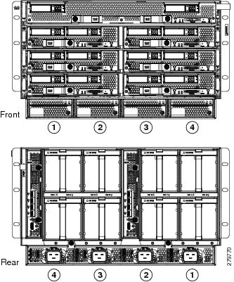
Compare the shipment to the equipment list provided by your customer service representative and verify that you have received the following items:
|
|
Step 3 |
Verify that all unused blade slots and power supply bays have blank covers. |
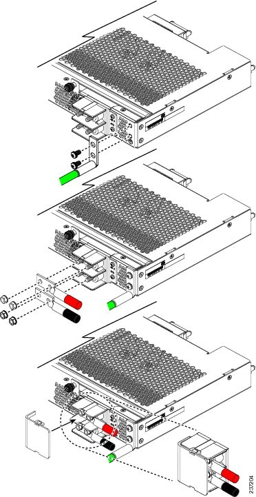
Attaching the Round Hole Adapter Kit to the Rails (Optional)
Note |
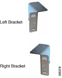
The chassis tool-less rails are designed for racks that have square mounting holes. You must use the round hole adapters (N20-CRMK2-RHA=) to install the chassis in racks that have round mounting holes. |
This round hole adapter kit allows you to adapt the rail kit (N20-CRMK2=) to install into rack (front and/or rear) posts that use either threaded or non-threaded round holes. Four adapters in the kit are for adapting the rail kit to install into rack posts with threaded round holes, and the other four adapters in the kit are for adapting the rail kit to install into rack posts with non-threaded round holes. You can use a combination of adapters based on the type of holes in the rack posts. Various sizes and lengths of screws are also included in the kit.
Procedure
|
Step 1 |
Insert the adapter tab into the mounting rail as shown in callout 1. |
|
Step 2 |
Slide the adapter up to lock it into position as shown in callout 2. |
|
Step 3 |
Secure the adapter into place using the provided pan-head screw as shown in callout 3. 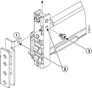
|
|
Step 4 |
Repeat steps 1to 3 for the other three adapters. |
 Feedback