Installing and Removing Components

This chapter describes how to remove components from the chassis and how to install components into the chassis. This section contains the following section:

Components

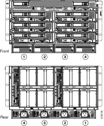
The following figure shows an empty Cisco UCS 5108 server chassis and identifies the front, back, and module slots.


Note


Whenever you remove a module from the chassis for an extended period of time, always replace the module with the appropriate blank panel. Failing to do so can result in heating and EMI issues. Blank panels can be ordered from Cisco Systems.


Figure 1. View of Cisco UCS 5108 Server Chassis

1

Front of chassis

5

Power supply slot (4 slots)

2

Chassis handle

6

Fabric interconnect or FEX slot (2 slots)

3

Rear of chassis

7

Fan slots (8 slots)

4

Half-width server slot (8 slots)

8

Power Distribution Unit (PDU) slot


Note


Before you install, operate, or service the system, see the Regulatory Compliance and Safety Information for Cisco UCS for important safety information.


Warning


IMPORTANT SAFETY INSTRUCTIONS


This warning symbol means danger. You are in a situation that could cause bodily injury. Before you work on any equipment, be aware of the hazards involved with electrical circuitry and be familiar with standard practices for preventing accidents. Use the statement number provided at the end of each warning to locate its translation in the translated safety warnings that accompanied this device. 
Statement 1071

SAVE THESE INSTRUCTIONS


Warning


This unit is intended for installation in restricted access areas. A restricted access area can be accessed only through the use of a special tool, lock and key, or other means of security. 
Statement 1017


Warning


Only trained and qualified personnel must be allowed to install, replace, or service this equipment. Statement 1030


Installing and Removing a Blade Server

There are two types of blade server supported, half-width and full-width. Their installation is similar but with important differences. For details, see the Blade Server Installation and Service Note for the type of blade server you are using. The server notes are available at the following URL: http://www.cisco.com/en/US/products/ps10280/prod_installation_guides_list.html

Installing and Removing a Blade Server Hard Drive

You can remove blade server hard drives without removing the blade server from the chassis. All other component replacement for a blade server requires removing the blade from the chassis. Unused hard drive bays should always be covered with cover plates (N20-BBLKD) to assure proper cooling and ventilation. The chassis is omitted from illustrations here to simplify the drawing.


Caution


To prevent ESD damage, wear grounding wrist straps during these procedures and handle modules by the carrier edges only.


Installing a Blade Server Hard Drive

Procedure

Step 1

Place the hard drive lever into the open position by pushing the release button.

Step 2

Gently slide the hard drive into the opening in the blade server until it seats into place.

Step 3

Push the hard drive lever into the closed position.


The following figure shows the positioning of a hard drive within a blade server.

Figure 2. Positioning a Hard Drive in a Blade Server (Cisco UCS B200 M1 shown)

Removing a Blade Server Hard Drive

Procedure

Step 1

Push the button to release the ejector, and then pull the hard drive from its slot.

Figure 3. Pressing the Button on the Front of the Hard Drive to Deploy the Lever (Cisco UCS B200 M1 shown)

1

Release button

2

Hard drive lever

Step 2

Place the hard drive on an antistatic mat or antistatic foam if you are not immediately reinstalling it in another blade server.

Step 3

Install a blank faceplate (N20-BBLKD) to keep dust out of the blade server if the slot will remain empty.


Installing and Removing Power Supplies


Note


The AC and DC power supplies are keyed to work only with the power distribution system in their respective chassis version. Mixing AC and DC in a given chassis is not supported.


Installing a Power Supply

All power supply models (N20-PAC5-2500W, UCSB-PSU-2500ACPL, or UCSB-PSU-2500DC48) install using the same process.

Procedure


Step 1

Place the power supply’s handle in the up position.

Step 2

Hold the power supply with both hands, and then slide it into the power supply bay,

Step 3

Press the handle down, and give the power supply a gentle push inward to ensure that the power supply is fully seated into the Power Distribution Unit (PDU).

Step 4

Tighten the captive screw.

Step 5

For an AC installation, plug the power cable into the corresponding 220 VAC–inlet connector on the PDU at the rear of the chassis. For a DC environment, see Connecting a DC Power Supply.

Note


Depending on the outlet receptacle on your rack’s power distribution unit, you may need the optional jumper power cord to connect the Cisco UCS 5108 server chassis to an outlet receptacle.

Step 6

Connect the other end of the power cable to the AC–power source.

Step 7

Verify the power supply is operating by checking the power supply LEDs. See LED Locations and Interpreting LEDs.

Figure 4. Positioning a Power Supply in the Cisco UCS Server Chassis

Note


Both grids in a power redundant system should have the same number of power supplies. If your system is configured for grid redundancy, slots 1 and 2 are assigned to grid 1 and slots 3 and 4 are assigned to grid 2. If there are only two power supplies in a redundant- mode chassis, they should be in slots 1 and 3. This would be a very unusual configuration, with a single B200 blade server in the chassis. A larger configuration would require two power supplies per grid. Slot and cord connection numbering is shown below.

Figure 5. Power Supply Bay and Connector Numbering (AC Version Shown)

Removing a Power Supply


Caution


If you are using the Cisco UCS 5108 server chassis with one power supply (this is only supported in earlier versions of the system software), removing the power supply will cause the servers and chassis to shut down. If you are using more than two power supplies, and you remove one of them, the servers continue to operate as long as the other power supplies are sufficient to meet the power requirements of the number of servers in the chassis.


Procedure


Step 1

Loosen the captive screw on the front of the power supply.

Step 2

Lift up the power supply’s handle to unseat the power supply.

Step 3

Using the lever, pull the power supply from its slot. Place your other hand under the power supply to support it while you slide it out of the chassis.

Step 4

Install a blank power supply filler panel (N20-CBLKP) if the power supply bay is to remain empty.


Installing and Removing a Power Distribution Unit (PDU)


Caution


The Power Distribution Unit should only be replaced by a Cisco certified technician. This section is for reference only.


Caution


You can not hot swap a PDU (N01-UAC1). The entire chassis will need to be shut down and all power cords should be unplugged before attempting this procedure.


Installing a PDU

Procedure


Step 1

Hold the PDU module from below, with the captive screws at the top of the module.

Figure 6. Positioning a PDU (N01-UAC1) in the Cisco UCS Server Chassis, AC Version

Step 2

Push the PDU module into the chassis until it seats properly. If power supplies are installed, you may need to partially remove them.

Step 3

Tighten the captive screws.

Step 4

If necessary, reseat the power supplies and restart the system to observe LED behavior.


Removing a PDU

Procedure


Step 1

Partially remove all installed power supplies. If a power supply is seated into the PDU, removal is difficult or impossible.

Step 2

Loosen the captive screws.

Step 3

Pull the PDU clear of the chassis by pulling on the captive screws. Support its weight from below.


Replacing an I/O Module (or UCS 6324 Fabric Interconnect For UCS Mini)

The chassis houses two I/O modules (IOMs) that allow the blade servers in the chassis to communicate with Cisco UCS fabric interconnects.

In the Cisco UCS Mini Server Chassis, the same slot that is used for an IOM is used for the Cisco UCS 6324 Fabric Interconnect. Up to two of these modules can be installed in the chassis.


Note


The Cisco UCS 2304 IOM cannot be installed in the same chassis with a UCS 2208XP or UCS 2204XP IOM except during migration.


Note


There is a version 2 of the UCS 2304 IOM. You cannot mix UCS-IOM-2304V2 and UCS-IOM-2304 in the same chassis. If you replace one UCS-IOM-2304 with UCS-IOM-2304V2, you must replace both IOMs with V2.

UCS-IOM-2304V2 requires Cisco UCS Manager 4.0(4) or later.


Removing an IOM or UCS 6324 Fabric Interconnect

Procedure


Step 1

Remove all cables from the IOM or UCS 6324 Fabric Interconnect.

Step 2

Loosen the captive screws on the IOM or UCS 6324 Fabric Interconnect.

Step 3

Pull the levers outward to unseat the IOM or UCS 6324 Fabric Interconnect.

Step 4

Using the levers, pull the IOM or UCS 6324 Fabric Interconnect from its slot.

Step 5

Only if the slot is to remain empty, install a blank IOM filler panel (N20-CBLKI).

Note


If you plan to remove an IOM or UCS 6324 fabric interconnect for an extended period of time, you must replace it with the N20-CBLKI blank to avoid EMI issues. Blanks can be ordered from Cisco.


Installing an IOM or UCS 6324 Fabric Interconnect

Procedure


Step 1

Make sure that the two levers at the front of the FEX or the UCS 6324 Fabric Interconnect are pulled open.

Step 2

Slide the FEX or UCS 6324 Fabric Interconnect into the chassis slot, ensuring that the module is fully seated.

Figure 7. Positioning an IOM or UCS 6324 Fabric Interconnect into the Server Chassis

Step 3

Close the levers and tighten the captive screw on each lever.

Step 4

Connect the networking cables (see SFP+ Transceivers and Proper FEX and Fabric Interconnect Port Connectivity ).

Step 5

Verify that the module is functioning correctly. See LED Locations and Interpreting LEDs.


Migrating from UCS 6200 to UCS 6454 Fabric Interconnects

You can migrate UCS 6200 Series FIs to UCS 6454 FIs.


Note


If you plan to migrate to UCS 2408 IOMs, you must first migrate from UCS 6200 Series FIs to UCS 6400 Series FIs. See Supported Migration Paths.


Supported Migration Paths

The following migration paths for FIs and IOMs are supported:

Starting Hardware

Migration To

UCS 6200 FI with 2200 IOMs

UCS 6400 Series FI with 2200 IOMs

UCS 6400 Series FI with 2200 IOMs

UCS 6400 Series FI with 2408 IOMs

Fabric Interconnect Migration Considerations

Ensure that the following prerequisites are met before beginning any procedures in this section:


Caution


Cisco UCS Manager Release 4.0(1a) is the minimum version that provides support for Cisco UCS 6454 Fabric Interconnects. To migrate from Cisco UCS 6200 Series to Cisco UCS 6454 Fabric Interconnects:

  • Cisco UCS 6200 Series Fabric Interconnects must be on Cisco UCS Manager Release 4.0(1) or a later release.

  • Cisco UCS 6454 Fabric Interconnects must be loaded with the same build version that is on the Cisco UCS 6200 Series Fabric Interconnect that it will replace.


Note


Cisco UCS 6454 FI requires Cisco UCS Manager 4.0(1a) or later. Cisco UCS 2408 IOM requires Cisco UCS Manager 4.0(4c) or later. If you will also be migrating to UCS 2408 IOM, upgrade to 4.0(4c) or later.


  • Licenses from Cisco UCS 6200 Series Fabric Interconnects are not transferable to Cisco UCS 6454 Fabric Interconnects. You must obtain licenses for the Cisco UCS 6454 Fabric Interconnects before you upgrade.

  • During migration, the Cisco UCS 6200 Series Fabric Interconnect and the Cisco UCS 6454 Fabric Interconnect must use the same allowed SSL protocol, either default or Only TLSv1.2, to successfully complete compatibility checks.

  • Cisco UCS 6454 Fabric Interconnects use the IDLE fill pattern for FC uplink ports and FC storage ports when using 8 Gbps speed.

    When migrating to Cisco UCS 6454 Fabric Interconnects and configuring FC Uplink Ports or FC Storage Ports at 8Gbps speed, ensure that the fill pattern is set as IDLE on the corresponding FC switch ports and the direct-attached FC storage array ports. If the fill pattern is not set as IDLE, FC uplink ports and FC storage ports operating at 8 Gbps might go to an errDisabled state, lose SYNC intermittently, or receive errors or bad packets.

    Cisco UCS 6454 Fabric Interconnects do not support 8 Gbps direct-attached FC connectivity (FC uplink ports or FC storage ports) without fill-pattern set to IDLE. When migrating to Cisco UCS 6454 Fabric Interconnects from Cisco UCS 6200 Series Fabric Interconnects, do one of the following:

    • Use a SAN switch between the Cisco UCS 6454 Fabric Interconnect and the storage array with 8 GB FC connectivity.

    • Upgrade the storage array to 16 GB or 32 GB FC connectivity.

  • Before migrating from Cisco UCS 6200 Series Fabric Interconnects to Cisco UCS 6454 Fabric Interconnects, ensure that you unconfigure the unified ports on the Cisco UCS 6200 Series Fabric Interconnects.

    After migrating to Cisco UCS 6454 Fabric Interconnects, reconfigure the unified ports based on their location on the Cisco UCS 6454 Fabric Interconnects, and reacknowledge the newly configured ports. For example, a unified port on a UCS 6248 Fabric Interconnect should be reconfigured on any port between 1 and 16 on a Cisco UCS 6454 Fabric Interconnect.

  • Upgrading the fabric interconnect should be done before upgrading to a new FEX/IOM or virtual interface card.

  • During fabric interconnect migration, image synchronization between fabric interconnects is not allowed. This is done to prevent incompatible images from getting synchronized. We recommend that you download B-Series and C-Series server software bundles again after migration is complete.

  • Do not attempt to implement new software features from the new Cisco UCS software version until all required hardware is installed.

  • Changes to the topology, such as the number of servers or uplink connections, should be performed after the fabric interconnect migration is complete.

  • Make a detailed record of the cabling between FEXes/IOMs and fabric interconnects. You must preserve the physical port mapping to maintain the server pinning already configured and minimize down time.

  • For a cluster configuration, both fabric interconnects must have symmetrical connection topologies between fabric interconnect and FEXes/IOMs.

  • Cisco UCS VIC 1455 and 1457 adapters support cables of 10G and 25G speed. However, the cables connecting Cisco UCS VIC 1455 or 1457 adapter ports to each 6454 fabric interconnect must be of uniform speed-either all 10G or all 25G cables. If you connect these adapter ports to a 6454 fabric interconnect through a mix of 10G and 25G cables, UCS rack-mount server discovery fails and ports may go to a suspended state.

  • Standalone installations should expect down time. Migrating or upgrading a fabric interconnect is inherently traffic disruptive.

  • A best practice would be to perform a full configuration and software backup before performing this hardware upgrade.

  • A WWN pool can include only WWNNs or WWPNs in the ranges from 20:00:00:00:00:00:00:00 to 20:FF:00:FF:FF:FF:FF:FF or from 50:00:00:00:00:00:00:00 to 5F:FF:00:FF:FF:FF:FF:FF. All other WWN ranges are reserved. When fibre channel traffic is sent through the UCS infrastructure the source WWPN is converted to a MAC address. You cannot use WWPN pool which can translate to source multicast MAC addresses. To ensure the uniqueness of the Cisco UCS WWNNs and WWPNs in the SAN fabric, Cisco recommends using the following WWN prefix for all blocks in a pool: 20:00:00:25:B5:XX:XX:XX

Port Mapping For Upgrades

The upgrade described here is primarily for upgrading a Cisco UCS 6248 fabric interconnect to a Cisco UCS 6454. The same considerations will also apply when upgrading a Cisco UCS 6296 fabric interconnect to a Cisco UCS 6454.


Note


If you are using appliance ports for direct attached storage, you must add VLANs to the ethernet uplinks. This will ensure that vNICS can properly pin on boot.


On the UCS 6248 fabric interconnect, you can separate the 32 physical ports in slot one into two contiguous pools, low numbered ports being Ethernet ports and high numbered ports being Fibre Channel ports. On the UCS 6454 fabric interconnect, you can configure the first 16 ports as Fibre Channel ports (when using Cisco UCS Manager releases earlier than 4.0(4), only ports 1-8 are unified ports).

Because a UCS 6248 has 32 ports in slot 1 and a UCS 6454 has all ports in slot 1, any ports on GEM slots will be removed during the hardware upgrade process.


Caution


If you ever need to change the pool sizes for slot 1, you must reboot the fabric interconnect, which can lead to a service disruption. If you ever need to change the pool sizes for slot 2, you must reset the expansion module in slot 2. To minimize disruption, plan to have at least a few Ethernet uplink and Fibre Channel uplink ports configured on slot 1. Implement this fail-safe after the upgrade is complete and the system restabilizes.


Migrating to UCS 6454 Fabric Interconnect

The steps in this section apply to the following supported scenarios:

  • Migrating from a UCS 6200 Series Fabric Interconnect to a UCS 6454 Fabric Interconnect


Note


Migration from UCS 6300 Series FIs to UCS 6400 Series is not supported at this time.


You can migrate from a UCS 6200 Series Fabric Interconnect to a UCS 6454 Fabric Interconnect. However, you cannot migrate back to a UCS 6200 Series Fabric Interconnect after you have migrated to a UCS 6454 Fabric Interconnect.

The UCS 6454 Fabric Interconnect is intended as a replacement for the UCS 6200 Series Fabric Interconnect, but not as a replacement for the higher speed (or 40Gb) UCS 6332/6332-16UP Fabric Interconnect. Therefore, Cisco has not tested or published a plan to migrate from UCS 6332/6332-16UP Fabric Interconnects to UCS 6454 Fabric Interconnects.

Unless otherwise noted, for more information about how to perform configuration procedures in Cisco UCS Manager for a particular step, see the appropriate Cisco UCS Manager configuration guide for Cisco UCS Manager Release 4.0.

Procedure


Step 1

Download Cisco UCS Manager, Release 4.0 or later versions to the UCS 6200 Series Fabric Interconnects and upgrade to this version.

Step 2

Evacuate traffic from the subordinate fabric interconnect to ensure there is no data traffic impact during migration.

See Firmware Management Guide, FI Traffic Evacuation

Step 3

Unconfigure all the server ports on the subordinate fabric interconnect.

Step 4

Power down the subordinate fabric interconnect by unplugging it from the power source.

If you are monitoring the migration using a KVM session, you may need to reconnect the KVM session when you power down the fabric interconnect.

Step 5

Mount the replacement UCS 6454 fabric interconnect into either the same rack or an adjacent rack.

See the Cisco UCS 6400 Series Fabric Interconnect Hardware Installation Guide.

Step 6

Disconnect the cables from the chassis FEXes/IOMs to the subordinate fabric interconnect ports in slot 1 on the UCS 6200 Series Fabric Interconnect.

Step 7

Connect these cables into the corresponding ports on slot 1 of one of the new Cisco UCS 6454 fabric interconnects, using the connection records to preserve the port mapping and the configured server pinning. To change the port mapping, especially while reconfiguring FC ports, you must reacknowledge the newly configured ports.

Step 8

Connect the L1/L2 cables that you disconnected onto the new Cisco UCS 6454 fabric interconnect. L1 connects to L1; L2 connects to L2.

Step 9

Connect the server and uplink cables.

See the Cisco UCS 6400 Series Fabric Interconnect Hardware Installation Guide.

Step 10

Connect the power to the new Cisco UCS 6454. It will automatically boot and run POST tests. If it reboots itself, this is a normal behavior.

Important


Directly connect the console port to a terminal and observe the boot sequence. You should at some point see the Basic System Configuration Dialog, where you will configure the switch as a subordinate interconnect. If you do not see this dialog, you either have different builds of software on your old primary and new subordinate, or the new subordinate has previously been part of a cluster and will need to have all configuration information wiped before it can be added to a cluster as a subordinate. In either case, immediately disconnect the L1 and L2 connections and complete the bringup as a standalone fabric interconnect, then correct the issue before proceeding further.

Step 11

Configure the server and uplink ports on the new Cisco UCS 6454 fabric interconnect.

Step 12

Wait for the new subordinate Cisco UCS 6454 fabric interconnect to automatically synchronize the configuration and database/state information from the primary UCS 6200 Series Fabric Interconnect.

Synchronization between primary and subordinate fabric interconnects can take several minutes. You may see an error message that will persist until the server ports are enabled.

The port configuration is copied from the subordinate switch to the new hardware.

Step 13

Verify that the data path is ready.

See Firmware Management Guide, Verifying the Data Path.

Ensure that all faults are resolved before proceeding.

  1. Verify and if necessary reconfigure the SAN pin group for FC ports in the associated service profile.

  2. Verify and if necessary reconfigure the LAN pin group for Ethernet ports in the associated service profile.

  3. Verify and if necessary reconfigure the port channel for uplink Ethernet ports.

Step 14

Reconfigure the server ports that you unconfigured in Step 3.

  1. If you have changed port mappings, you may need to reacknowledge the chassis or rack server connected to the subordinate fabric interconnect.

  2. Verify and if necessary reconfigure Ethernet ports as server ports.

Step 15

Restart stopped traffic flows by disabling fabric evacuation.

Step 16

Promote the subordinate fabric interconnect to primary, and then repeat the process on the second new UCS 6454.

Cable the second new fabric interconnect identically to the first, and then allow the reconfiguration to be applied to the second new fabric interconnect.


Migrating to UCS 2408 IOMs


Note


The Cisco UCS component compatibility with the UCS 2408 IOM is as follows:

  • Requires Cisco UCS Manager 4.0(4e) or later software

  • Supported with the UCS 6400 Series FIs only

  • Supported with Cisco UCS 1300 and 1400 Series Virtual Interface Cards (VICs) only

  • Supported with Cisco UCS B-Series M4 and M5 server generations only


The steps in this section apply to the following supported scenarios:

  • Migrating from UCS 6400 Series FIs with 2200 Series IOMs to UCS 6400 Series FIs with UCS 2408 IOMs.


Note


If you plan to migrate to UCS 2408 IOMs, you must first migrate from UCS 6200 Series FIs to UCS 6400 Series FIs. See Migrating from UCS 6200 to UCS 6454 Fabric Interconnects.


Note


Migration from UCS 2300 Series IOMs to UCS 2400 Series IOMs is not supported at this time.


Note


If the primary and the subordinate IOMs are different models, the overall status of the IOMs is shown as Peer Comm Problem. However, the IOMs can still be replaced.


IOM 2408 connects only to the 6454 Fabric Interconnects. Please follow the steps described in 6454 migration-guide to ensure the UCS domains with IOM 2200 series have 6454 Fabric Interconnects.

Procedure


Step 1

UCS IOM 2408 connects only to the UCS 6454 Fabric Interconnects. Follow the steps to ensure the UCS domains with IOM 2200 series have 6454 Fabric Interconnects. See Migrating from UCS 6200 to UCS 6454 Fabric Interconnects.

Step 2

Ensure the supported 25-GbE transceivers and cables are used to connect the IOM 2408 with FI 6454. See the Cisco UCS 2408 Fabrix Extender Data Sheet.

Step 3

See the list of UCS components compatible with 2408 IOM above this procedure.

Use the hardware replacement procedures in Replacing an I/O Module (or UCS 6324 Fabric Interconnect For UCS Mini).

Step 4

Back up and export the Cisco UCS Manager configuration.

Step 5

Perform UCSM infrastructure upgrade to version 4.0(4e) or above – Fabric Interconnect and IOM

Step 6

Before starting the IOM migration, ensure that the UCS domain is fully operational with no faults.

Step 7

From UCS Manager, validate that cluster HA redundancy state is present, that there are no faults, and identify the subordinate FI 6454 in the domain.

Step 8

To have minimal traffic loss during migration, ensure there are redundant paths from the blade servers over fabrics A and B.

Note


Because inflight packet loss is expected during the IOM migration, perform the next set of operations only during a maintenance window.

Step 9

On the subordinate FI 6454, unconfigure server ports that connect to the migrating IOM 220x. When you unconfigure the server ports, the primary FI takes over traffic forwarding.

Step 10

Disconnect cables connecting the subordinate FI 6454 and the corresponding IOM 220x.

Step 11

Remove and replace the migrating IOM 220x with IOM 2408. Connect the IOM 2408 to the subordinate FI 6454 with 25-gigabit ethernet cables. At this point, the migrating UCS chassis has a mix of IOM 220x and IOM 2408.

Step 12

Configure server ports from UCS Manager on the subordinate FI 6454 ports connected to the IOM 2408, one-by-one to each chassis. Verify the 25GbE links come up between the IOM and FI.

Step 13

Wait for auto-upgrade of IOM 2408 to complete. Due to a known limitation, the migration of IOM 2208 to IOM 2408 requires a reboot of the FI after replacing the IOM. After the reboot of the subordinate FI, wait for the subordinate FI and migrating IOM 2408 to be fully operational with traffic resuming over the subordinate FI fabric.

Note


At this time, when migrating from UCS 2208 IOM to 2408 IOM, Vethernet interfaces are not pinned to server interfaces (HIFPC) dynamically on the FI. You must reboot the FI to bring up the Vethernet interfaces. Refer to the Release Notes for 4.0(4e) for more details. The issue is being tracked in CDETS CSCvr46327.

RNE for 4.0(4e) UCSM

Step 14

Ensure the IOM 2408 has loaded the latest firmware and verify there are no faults on UCS chassis with the new IOM 2408. Cluster HA redundancy will not be present due to mismatch of IOM's on the migrating UCS chassis but traffic forwarding over FI's is not affected.

Step 15

After completing IOM migration on the subordinate FI, repeat steps 9 to 14 to replace the other IOM 220x connected to the primary FI 6454 and complete the IOM 2408 migration for the UCS domain.

Note


After reload of theprimary FI, fabric cluster failover will happen. However, this does not affect data traffic forwarding in the UCS domain.

Step 16

With the completion of IOM 2408 migration on all the UCS 5108 chassis in the domain, verify that cluster HA redundancy is back on the Fabric Interconnects, that there are no faults on the UCS Manager, and that traffic is forwarding over the new IOM 2408s on both Fabric A and B.


Migrating to UCS 6300 Series Fabric Interconnects

Before starting the hardware migration, make the following changes to Cisco UCS Manager software:

  • Download Cisco UCS Manager, Release 3.1 to the UCS 6200 Series Fabric Interconnects and upgrade to this version.

  • Download Cisco UCS Manager, Release 3.1 to the UCS 6300 Series Fabric Interconnects.

  • Ensure that all fabric interconnects have the same versions of the kickstart, system, and UCS Manager images.

  • Upgrade the B-bundle if you plan to use the UCS 2304 IOM.


    Note


    There is a version 2 of the UCS 2304 IOM. UCS-IOM-2304V2 requires Cisco UCS Manager 4.0(4) or later. You cannot mix UCS-IOM-2304V2 and UCS-IOM-2304 in the same chassis.


  • If you plan to migrate to a UCS 6332-16UP Fabric Interconnect, determine the number of VSANs that are configured in your system. If more than 15 VSAN IDs are configured, reduce this number to 15 or less to avoid possible configuration issues with Fibre Channel or FCoE ports on a UCS 6332-16UP Fabric Interconnect. It is not necessary to reduce the number of configured VSANs before migrating to a UCS 6332 Fabric Interconnect.

You can migrate from a UCS 6200 Series Fabric Interconnect to a UCS 6300 Series Fabric Interconnect. You can also revert back to UCS 6200 Series Fabric Interconnect after you have migrated to a UCS 6300 Series Fabric Interconnect.

You cannot migrate from a UCS 6100 Series Fabric Interconnect to a UCS 6300 Series Fabric Interconnect.

Migrating to 6300 Series Fabric Interconnect Modules

The steps in this section apply to the following scenarios:

  • Migrating from a UCS 6248 Fabric Interconnect to a UCS 6332 Fabric Interconnect with a UCS 2204 or UCS 2208 IOM

  • Migrating from a UCS 6248 Fabric Interconnect to a UCS 6332-16UP Fabric Interconnect with a UCS 2304 IOM

  • Migrating from a UCS 6296 Fabric Interconnect to a UCS 6332 Fabric Interconnect with a UCS 2204 or UCS 2208 IOM

  • Migrating from a UCS 6296 Fabric Interconnect to a UCS 6332-16UP Fabric Interconnect with a UCS 2304 IOM


Note


Following a migration, remove port-related configurations in the fabric interconnect and then reconfigure the ports. For example, you must reconfigure the SPAN destination ports after migrating from a UCS 6200 Series Fabric Interconnect to a UCS 6300 Series Fabric Interconnect.

Note


As stated in the Prerequisites, make sure that you reduce the number of configured VSANs in your UCS system to 15 or less before you begin the migration, if you plan to migrate to a UCS 6332-16UP Fabric Interconnect. It is not necessary to reduce the number of configured VSANs before migrating to a UCS 6332 Fabric Interconnect.


Procedure


Step 1

If you are upgrading to the Cisco UCS 6332-16UP, verify that the environment does not exceed 15 VSANs.

Step 2

Download Cisco UCS Release 3.1(1) or later from the Cisco Support site at https://software.cisco.com/download/navigator.html and upgrade the existing Cisco UCS 6200 Series domain to Release 3.1(1) or later.

Step 3

Fail over traffic from the subordinate server to the primary server. You can do this in several ways, as listed in the following table:

Failover Method

Considerations

Disable uplink

Individually disable the uplink ports for Ethernet, Fibre Channel, and FCoE connections.

Ethernet only: A virtual network interface card (vNIC) with network control policy with a warning on “Action on Uplink Fail” will not be disabled. Thus, the NIC needs to be disabled manually for failover.

Disable all uplink interfaces

With a single click, this method disables all uplinks that are not in a port channel. This method needs to be implemented on Ethernet, Fibre Channel, and FCoE connections.

Ethernet only: As with the disable uplink method, vNICs with network control policy with a warning on “Action on Uplink Fail” are not disabled. Manual intervention is required.

Disable all port channels

With a single click, this method disables all uplinks that are in a port channel, links that are not in a port channel are excluded. This method needs to be implemented on Ethernet, Fibre Channel, and FCoE connections.

Ethernet only: As with the disable uplink method, vNICs with network control policy with a warning on “Action on Uplink Fail” are not disabled. Manual intervention is required.

Fabric evacuation

This method disables all the server ports, which disables both the vNIC and virtual host bus adapter (vHBA) for the host. This method does not disable the virtual interface (VIF) on Cisco UCS C-Series servers that are directly connected to the fabric interconnect. For those connections, you need to disable the ports manually.

Note


For Cisco UCS domains that use blades only, Cisco recommends the fabric evacuation method. This approach provides the fastest way to validate proper traffic failover. It also lets you back out the failover simply by turning the fabric evacuation off.

If Cisco UCS C-Series servers are directly attached to the fabric interconnect, then manually disable either the port or the uplink for Ethernet, Fibre Channel, and FCoE.

Step 4

Verify that traffic is flowing over the primary fabric interconnect.

Step 5

If the Cisco Nexus 2232PP 10GE is being retired and replaced by Cisco Nexus 2348UPQ 10GE, then decommission and remove old fabric extender from Cisco UCS Manager.

Step 6

Port schemes between UCS 6200 and 6300 Series FIs are vastly different, so unconfigure all the ports on the subordinate interconnect and reconfigure the ports on the new fabric interconnect after it joins the cluster.

Note


You do not need to delete the port-channel groups because they can be reused, but you should verify that the individual ports are removed from LAN and SAN port channels, VLAN groups, etc..

Step 7

Remove the cable from the downed subordinate fabric interconnect.

If you are replacing the IOM and Cisco Nexus 2232 with the Cisco UCS 2304 and Cisco Nexus 2348-UPQ, then make the replacement now.

Step 8

Install the new Cisco UCS 6332 fabric interconnect and connect the L1 to L2 connections between the Cisco UCS 6200 Series primary interconnect to the Cisco UCS 6332 platform subordinate interconnect.

Step 9

Reconnect the components (IOM, Cisco Nexus 2200 and 2300 Series, and Cisco UCS C-Series servers) to the Cisco UCS 6332 platform subordinate interconnect according to your port planning table.

Step 10

Power up the Cisco UCS 6332 platform subordinate interconnect. If it is correctly cabled with the correct software version, then the subordinate interconnect will recognize that it is connecting to an existing cluster.

Step 11

Enter show cluster extended-state to verify the cluster state.

Step 12

Configure the ports (Fibre Channel ports, server ports, appliance ports, breakout ports, uplink ports, etc.) on the Cisco UCS 6332 platform subordinate fabric interconnect.

Step 13

Verify server discovery. The IOM discovery process on the Cisco UCS 6332 platform subordinate interconnect may take a few minutes to complete and become operational. In certain situations, you may need to acknowledge the IOM (choose Equipment > Chassis > Chassis X > IO Modules > IO Module X).

  1. Cisco UCS C-Series servers that are directly connected with dual adapters or are connected to a different port require server acknowledgment to properly update the port mapping. To reduce the number of server reboots to one, you can perform this step after the other fabric interconnect has been replaced.

  2. For servers connected to the Cisco Nexus 2200 platform fabric extenders, in most cases a fabric extender reacknowledgment will reestablish a connection. Otherwise, a server reacknowledgment is needed.

Step 14

After all port configuration processes are complete, including the process of adding ports back into LAN and SAN port channels and VLAN groups, you need to validate LAN and SAN connectivity. Use the appropriate show commands, such as the following:

  • show interface status

  • show port channel summary

  • show interface trunk

  • show flogi database

  • show fcns database

Note


Note that a Cisco UCS M4 server with a Cisco UCS VIC 1340 and a port expander that is connected to a Cisco UCS 2304 IOM will be connected as a native 40-Gbps port. You can verify this connection by entering the show interface status command in the Cisco NX-OS Software shell.

Step 15

Reestablish flow on the subordinate fabric interconnect, the Cisco UCS 6332 platform.

If a method other than fabric evacuation is used, then enable uplinks for Ethernet, Fibre Channel, and FCoE.

Note


Some backplane ports may report link down because no service profile is associated with that server or the host is powered off.

Step 16

Verify that traffic is flowing normally on the Cisco UCS 6332 platform subordinate interconnect.

Step 17

After verifying traffic flow, promote the Cisco UCS 6332 platform subordinate interconnect to primary status by entering the cluster lead b command in the local-mgmt shell on the primary fabric interconnect.

Step 18

Enter the show cluster extended-state command to verify that the primary role has switched to the Cisco UCS 6332 platform and that high availability (HA) is in the ready state.

Step 19

Repeat the steps 3 through 14 to replace the other Cisco UCS 6200 Series Fabric Interconnect.

Step 20

(Optional) Promote fabric interconnect A to the primary role with the command cluster lead a in the local-mgmt shell of the primary fabric interconnect (B).

Step 21

Check for faults from old configurations, policies, software packages, etc. Remove any noncompliant configurations, policies, and software packages to clear faults.


Installing and Removing a Fan Module

You can hot swap a fan module (N20-FAN5) without causing an electrical hazard or damage to the system. However, you can only remove one fan module while the system is operating. Removing more than one fan module could cause overheating.


Note


When a fan is removed, louvers inside the chassis prevent recirculation of air into the system or loss of cooling. However, you should not leave the chassis for extended periods of time without all fan modules in place.


Installing a Fan Module

Procedure


Step 1

Hold the fan module with the spring latch at the top of the module.

Step 2

Push the fan module into the chassis until it seats properly and the spring latch snaps into place.

Step 3

Listen for the fans if the chassis is powered on. You should immediately hear it operating. If you do not hear it, ensure that the fan module is inserted completely in the chassis and the faceplate is flush with the outside surface of the chassis.

Step 4

Verify that the LED behavior is as expected. See LED Locations and Interpreting LEDs.

Figure 8. Positioning a Fan Module (N20-FAN5) in the Cisco UCS Server Chassis

Removing a Fan Module

Procedure


Step 1

Hold the fan module by its handle.

Step 2

Press down on the spring latch at the top of the fan module.

Step 3

Pull the fan module clear of the chassis.

Note


The chassis is designed to have all fan modules in place and operating at all times. Do not leave a fan module bay empty for longer than is necessary to replace it with a new fan module.