Installing the Fabric Interconnect

This chapter contains the following topics:

Cisco UCS Fabric Interconnect 6664 and Cisco UCS Fabric Interconnect 6652 Installation

The Cisco UCS 6600 Series Fabric Interconnect product family consists of the following different models.

Model

Cisco PID

Notes

Cisco UCS 6664 Fabric Interconnect

UCS-FI-6664

2 rack-unit (2U) chassis supporting Ethernet, FCoE, and FC ports. MACsec enabled.

Cisco UCS 6652 Fabric Interconnect

UCS-FI-6652

1 rack-unit (1U) chassis supporting Ethernet, FCoE, and FC. MACsec enabled.

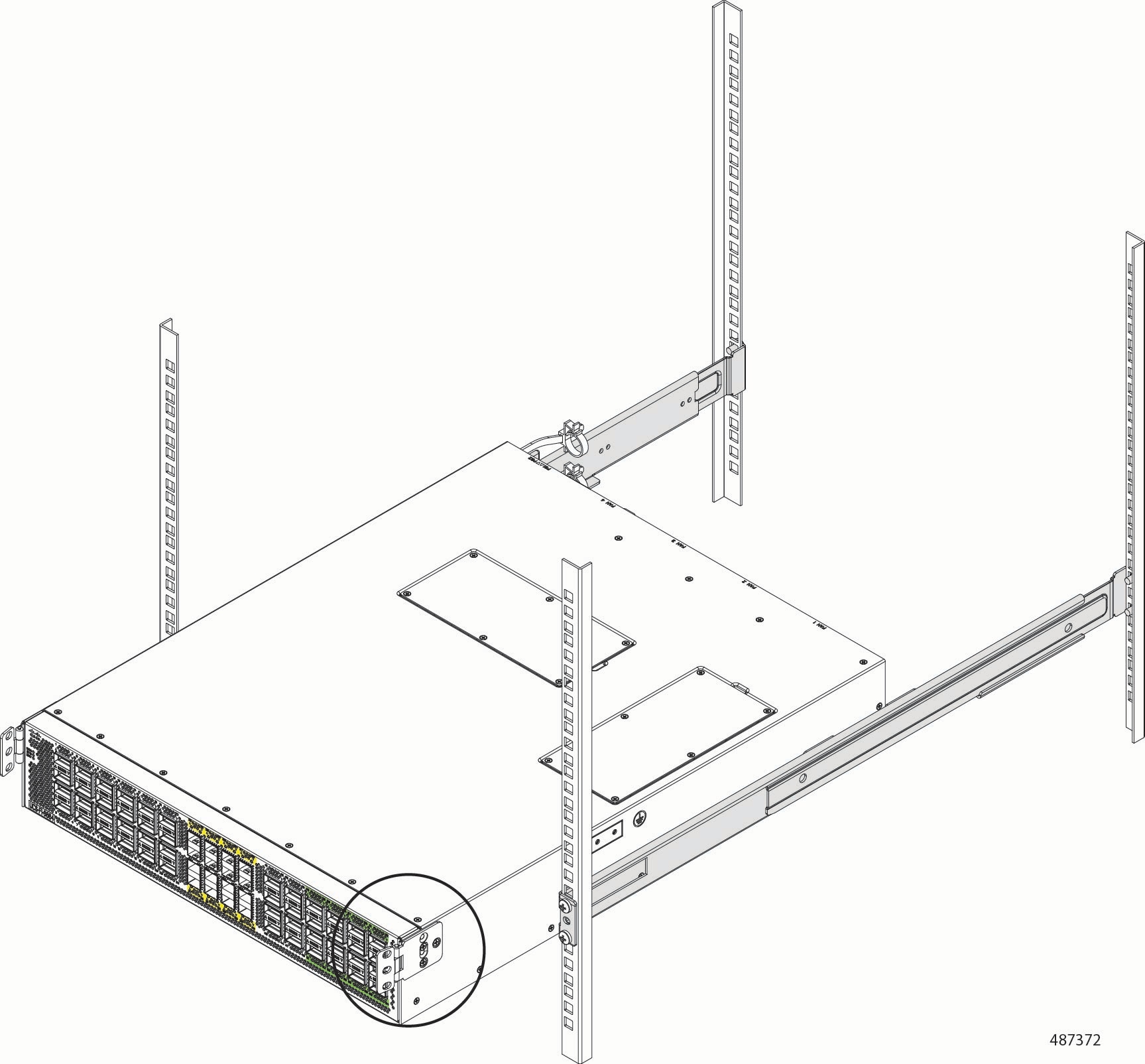
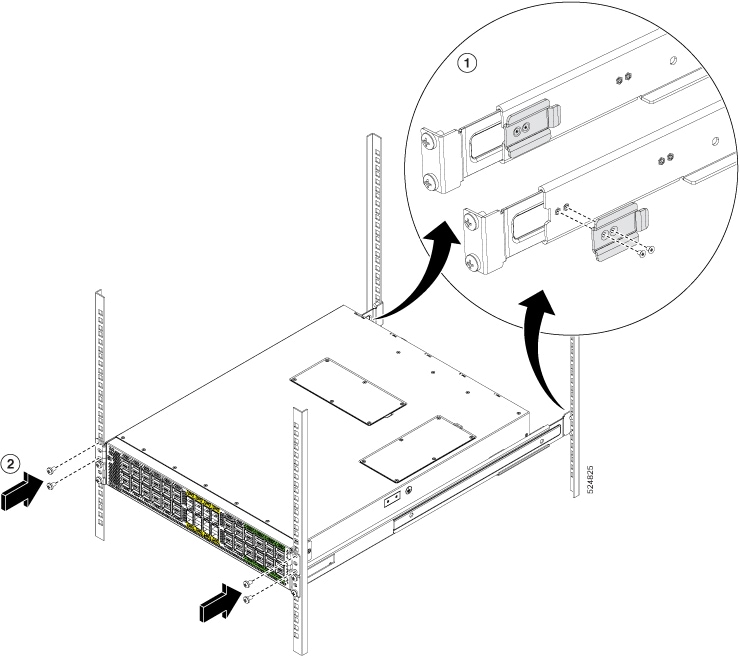
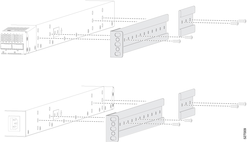
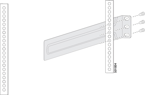
Both models of the Cisco 6600 Series Fabric Interconnect have many similarities as part of the overall installation process. However, there are some differences, primarily due to the different physical form factor of each.

You can assume that installation are the same for each model unless documentation explains otherwise.

Installation Options with Rack-Mount Kits

The rack-mount kit enables you to install the fabric interconnect into racks of varying depths. Position the fabric interconnect with easy access to either the port connections or the fan and power supply modules.

The rack-mount kit you use depends on the model of fabric interconnect you are installing:

  • For the UCS-FI-6664, install the fabric interconnect using rack-mount kit UCS-ACC-6664, which you can order from Cisco. This option for the 2U Fabric Interconnect offers you easy installation, greater stability, increased weight capacity, added accessibility, and improved removability with front and rear removal.

  • For the Cisco UCS-FI-6652, install the fabric interconnect using rack-mount kit UCS-ACC-6652, which you can order from Cisco. This option for the 1U Fabric Interconnect offers you easy installation, greater stability, increased weight capacity, added accessibility, and improved removability with front and rear removal.

The rack or cabinet that you use must meet the requirements listed the in General Requirements for Cabinets and Racks.


Note


You are responsible for verifying that your rack and rack-mount hardware comply with the guidelines that are described in this document.


Install a Rack

Before you install the fabric interconnect, you must install a standard four-post, 19-inch EIA data center rack (or a cabinet that contains such a rack) that meets the requirements listed in Overview of Racks.

Procedure


Step 1

Bolt the rack to the concrete subfloor before moving the chassis onto it.

Warning


Statement 1048—Rack Stabilization

The rack stabilizing mechanism must be in place, or the rack must be bolted to the floor before installation or servicing. Failure to stabilize the rack can cause bodily injury.

Step 2

If the rack has bonded construction, connect it to the earth ground. This action enables you to easily ground the fabric interconnect and its components and to ground your electrostatic discharge (ESD) wrist strap to prevent damaging discharges when you handle ungrounded components before installing them.

Step 3

Include one or two power sources at the rack. For AC power, provide a power receptacle.

Warning


Statement 1018—Supply Circuit

To reduce risk of electric shock and fire, take care when connecting units to the supply circuit so that wiring is not overloaded.

Note


If you are not using power redundancy or are using n+1 redundancy, you need only one power source. If you are using n+n redundancy, you need two power sources.


Unpacking and Inspecting a Fabric Interconnect

Before you install a new chassis, unpack and inspect it to be sure that you have all the items that you ordered. Verify that the fabric interconnect was not damaged during shipment. If anything is damaged or missing, contact your customer representative immediately.


Caution


When you handle the chassis or its components, follow ESD protocol at all times to prevent ESD damage. This protocol includes but is not limited to wearing an ESD wrist strap that you connect to the earth ground.


Tip


Do not discard the shipping container when you unpack the fabric interconnect. Flatten the shipping cartons and store them. If you need to move or ship the system in the future, you will need this container.


Procedure


Step 1

Compare the shipment to the equipment list that is provided by your customer service representative. Verify that you have received all of the ordered items.

The shipment should include:

  • Fabric interconnect, which includes these installed components:

    • Two power supplies (with the airflow direction being the same as for the fan modules):

      • 1400-W AC power supply

        • Port-side exhaust AC power supply with blue coloring (UCS-PSU-6600-AC)

    • Four fan modules (all fan and power supply modules must have the same airflow direction)

      • For the 2U Fabric Interconnect (UCS-FI-6664): Port-side exhaust airflow with blue coloring (UCS-FAN-6664)

      • For the 1U Fabric Interconnect (UCS-FI-6652): Port-side exhaust airflow with blue coloring (UCS-FAN-6652)

  • Accessory kit, either UCS-ACC-6664 for the 2U fabric interconnect or UCS-ACC-6652 for the 1U fabric interconnect:

    • Rack Mount Kit

    • Ground Lug

Step 2

Check the contents of the box for damage.

Step 3

If you notice any discrepancies or damage, send this information to your customer service representative by email:

  • Invoice number of the shipper (see the packing slip)

  • Model and serial number of the missing or damaged unit

  • Description of the problem and how it affects the installation


Planning How to Position the Fabric Interconnect in the Rack

The fabric interconnect is designed so that you can have cool air flow through the fabric interconnect by entering the power supply side and exhausting out the port side (port-side exhaust airflow).

For port-side exhaust airflow, the fabric interconnect must have port-side exhaust fan and AC power supply modules with blue coloring on fan modules and AC power supplies.

Plan the positioning of the fabric interconnect so that its ports are located close to ports on connected devices or so that the fan and power supply modules are conveniently located in a maintenance aisle. Order the modules that move coolant air in the appropriate direction from the cold aisle to the hot aisle.


Note


All fan and power supply modules in the same fabric interconnect must operate with the same direction of airflow. The air intake portion of the fabric interconnect must be located in a cold aisle.


Installing the Cisco UCS 6664 Fabric Interconnect Using the Rack Installation Kit

To install the UCS 6664, attach mounting brackets to the rack, install slider rails on the rear of the rack, slide the fabric interconnect onto the slider rails, install the retainer brackets, and secure the fabric interconnect to the rack with the retainer clips. Typically, the front of the rack is the side easiest to access for maintenance.


Note


You supply the twelve 10-32 or 12-24 screws required to mount the slider rails and fabric interconnect to the rack.

Before you begin

  • Inspect the Cisco UCS 6664 Fabric Interconnect (UCS 6664) shipment to ensure that you have everything ordered.

  • Verify that the UCS 6664 rack-mount kit (UCS-ACC-6664) includes these parts:

    • Rack-mount brackets (2)

    • Rack-mount front-mount brackets (2)

    • Rack-mount slider rails (2)

    • Rack-mount retainer clips (2)

    • Flat head screws M4 (6)

    • Flat head screws M3 (4)


    Note


    Twelve Phillis-head pan-screws are required for full installation. You will need to supply these screws. They are not provided in the rack-mount kit.


  • Verify that the rack is installed and secured to its location.

Procedure


Step 1

Install two rack-mount brackets to the rack.

  1. Position the front-mount brackets so that the UCS 6664 fan and power supply modules will be in the cold aisle.

  2. Position a front-mount bracket so that it aligns to the desired position in the rack and secure the bracket with 12-24 screws or 10-32 screws, depending on the rack thread type (see the figure). Tighten 12-24 screws to 30 in-lb (3.39 N·m) of torque. Tighten 10-32 screws to 20 in-lb (2.26 N·m) of torque.

    Illustration showing attaching a front mounting bracket to the rack. In this illustration, the front-mount bracket (shaded) is aligned with corresponding screw holes in the equipment rack, and two screws are aligned to insert through the external face of the front mounting bracket and into the screw holes in the equipment rack.
  3. Repeat Step 1 for the other front rack-mount bracket on the other side of the rack and be sure to position that bracket horizontally to the same level as the first bracket.

Step 2

If you are not installing the chassis into a grounded rack, attach a customer-supplied grounding wire to the chassis as explained in Grounding the Chassis. If you are installing the chassis into a grounded rack, skip this step.

Step 3

Install the slider rails on the rack or cabinet.

  1. Determine which two posts of the rack or cabinet you should use for the slider rails. Of the four vertical posts in the rack or cabinet, two will be used for the front mount brackets attached to the easiest accessed end of the chassis. The other two posts will have the slider rails.

  2. Position a slider rail at the desired level on the back side of the rack and slide it into the front-mount bracket already installed. Secure with 12-24 screws or 10-32 screws, depending on the rack thread type (see the figure). Tighten 12-24 screws to 30 in-lb (3.39 N·m) of torque. Tighten 10-32 screws to 20 in-lb (2.26 N·m) of torque.

    Illustration showing attaching a slider rail (shaded). In this illustration, the slider rail is sliding from the rear of the equipment rack into the previously installed front-mount bracket, and two screws are aligned to insert through the external face of the rear mounting bracket and into the screw holes in the equipment rack.
  3. Repeat Step 3 to attach the other slider rail to the other side of the rack.

    Make sure that the slider rails are at the same level. Use a level tool, tape measure, or carefully count the screw holes in the vertical mounting rails.

Step 4

Insert the UCS 6664 into the rack and attach it.

  1. Align the four holes in one side of front mount brackets to three holes on the left or right side of the chassis (see the figure).

    Illustration showing attaching the side mounting brackets to each side of the chassis. In this illustration, the side-mounting brackets are aligned with corresponding screw holes on the front sides of the fabric interconnect, and the screws are lined up to insert through the external face of the side mounting brackets and into the screw holes in the chassis.
  2. Use three M4 x 6 mm screws to attach the bracket to the chassis. Tighten each screw to 11 to 15 in-lb (1.2 to 1.7 N·m).

  3. Repeat Step 4 to attach the second front mount bracket to the other side of the chassis.

Step 5

Insert the UCS 6664 into the rack and attach it.

  1. Holding the UCS 6664 with both hands, position the fabric interconnect onto the rack-mount brackets and carefully slide the chassis into the rack (see the figure).

    Illustration showing the beginning of installing the fabric interconnect into the equipment rack. In this illustration, the chassis is aligned with the slider rails and is being paritally inserted into the rack by using the slider rails

Step 6

Rotate one front mount bracket so that it fits against the rack.

Illustration showing the continuation of installing the fabric interconect into the equipment rack. In this illustration, one of the front mounting bracket is being rotated to provide clearance at the front of the chassis to install the chassis completely flush with the face of the equipment rack.

Step 7

Secure the mounting brackets to the rack.

  1. Tighten the 10-32 screws to 20 in-lb (2.26 N·m) or tighten the 12-24 screws to 30 in-lb (3.39 N·m).

  2. Repeat Step 6 to attach the other front mount bracket on the other side of the chassis.

    Note


    You might need to slide the chassis out of the rack a short distance to allow clearance to rotate the mounting bracket into the correct position to attach it to the rack.

Step 8

Insert the retainer clip to hold the chassis in place.

  1. Align the retainer clip to the inside of the back of the slider rail. Make sure to hook the flange to the cutout on the bracket and align the screw holes (see the figure).

  2. Attach the two M3 X 4mm screws to secure the retainer clip (see the figure).

    Illustration showing the completely installed chassis being secured to the equipment rack. In this illustration, a close up illustration shows aligning the slider-rail retaining clip with the corresponding screw holes in each slider rail, and two screws aligning to insert through the screwholes in the retaining clip to secure the clip to the slider rail. Also, in the background, the chassis flush with the equipment rack and two screws per side are aligning to install thorugh the exterior face of the front-mounting brackets and sink into the equipment rack.
  3. Repeat Step 7 to attach the other retainer clip on the other side of the chassis.


What to do next

Provide grounding for the fabric interconnect.

Go to Grounding the Chassis.

Installing the Cisco UCS 6652 Fabric Interconnect Using the Rack Installation Kit

To install the UCS 6652, attach the front mounting brackets to the fabric interconnect and secure the fabric interconnect to the front of the rack. Typically, the front of the rack is the side easiest to access for maintenance.


Note


You must supply twelve 10-32 or 12-24 screws, depending on your rack type. These screws are required to secure the rails to the rack.


Before you begin

  • Inspect the Cisco UCS 6652 Fabric Interconnect (UCS 6652) shipment to ensure that you have everything ordered.

  • Make sure that the UCS 6652 rack-mount kit includes these parts:

    • Front rack-mount brackets (2)

    • Rear rack-mount brackets (2)

    • Slider rails (2)

    • M4 x 0.7 x 7-mm Phillips countersink screws (10). You will use eight of these screws to install the chassis into the rack.

  • Make sure that the rack is installed and secured to its location.

Procedure


Step 1

Install two front rack-mount brackets and the two rear rack-mount brackets to the fabric interconnect as follows:

  1. Position the UCS 6652 so that its fan and power supply modules will be in the cold aisle.

  2. Position the front rack-mount bracket and the rear rack-mount bracket so that its screw holes are aligned to the screw holes on the side of the chassis.

    Note


    You can align the holes in the rack-mount bracket to the holes on the side of the chassis (see the two ways to mount these brackets on a typical chassis, in following figure). The holes that you use depend on the requirements of your rack and the amount of clearance required for interface cables (3 inches [7.6 mm] minimum) and module handles (1 inch [2.5 mm] minimum).

    Illustration showing two views of attaching the mounting bracket (shaded) into the sides of the chassis. In the top view, the front bracket is aligned with the corresponding screw holes, and the screws are sinking thorough the mounting bracket into the screw holes. In the bottom view, the same content is shown for the rear mouting bracket attaching to the rear of the chassis.
  3. Secure the front-mount bracket and the back-mount bracket to the chassis using four M4 screws and tighten each screw to 12 in-lb (1.36 N·m) of torque.

  4. Repeat Step 1 for the other front rack-mount bracket and the other back-mount bracket on the other side of the fabric interconnect and be sure to position that bracket the same distance from the front of the fabric interconnect.

    Note


    Depending on the chassis depth, the back rack-mount bracket may not fit. In that case the back rack-mount bracket is not needed.

Step 2

If you are not installing the chassis into a grounded rack, you must attach a customer-supplied grounding wire to the chassis as explained in Grounding the Chassis. If you are installing the chassis into a grounded rack, you can skip this step.

Step 3

Install the slider rails on the rack or cabinet as follows:

  1. Determine which two posts of the rack or cabinet you should use for the slider rails. Of the four vertical posts in the rack or cabinet, two will be used for the front mount brackets attached to the easiest accessed end of the chassis, and the other two posts will have the slider rails.

  2. Position a slider rail at the desired level on the back side of the rack and use 12-24 screws or 10-32 screws, depending on the rack thread type, to attach the rails to the rack (see the following figure). Tighten 12-24 screws to 30 in-lb (3.39 N·m) of torque and tighten 10-32 screws to 20 in-lb (2.26 N·m) of torque.

    Illustration showing attaching a slider rail (shaded) to the rear of the equipment rack. In this illustration, the slider rail (shaded) is aligning with screw holes in the rack, and three screws are aligned to insert through the external face of the slider raik and sink into the screw holes in the equipment rack.
  3. Repeat Step 3 to attach the other slider rail to the other side of the rack.

    To make sure that the slider rails are at the same level, you should use a level tool, tape measure, or carefully count the screw holes in the vertical mounting rails.

Step 4

Insert the UCS 6652 into the rack and attach it as follows:

  1. Holding the UCS 6652 with both hands, position the two rear rack-mount brackets on the fabric interconnect between the rack or cabinet posts that do not have slider rails attached to them (see the following figure).

    Illustration showing the installation of the chassis. In this illustration, the front and rear rails (shaded) are sliding together as the chassis is being inserted into the rack, which is indicated by two dark arrows.
  2. Align the two rear rack-mount guides on either side of the fabric interconnect with the slider rails installed in the rack. Slide the rack-mount guides onto the slider rails, and then gently slide the UCS 6652 all the way into the rack until the front rack-mount brackets come in contact with two rack or cabinet posts.

    Note


    If you attached a grounding cable to the chassis, you might need to bend one of the rack-mount rails slightly to allow the grounding lug to go behind the rail.

  3. Holding the chassis level, insert screws (12-24 or 10-32, depending on the rack type) in each of the two front rack-mount brackets (using a total of six screws) and into the cage nuts or threaded holes in the vertical rack-mounting rails (see the following figure).

    Illustration shows the chassis installed and flush with the rack. In this illustration, the rear rail is completely inserted into the front sliding rail (both shaded), and three screws are sligned to insert trhough the front face of the mounting bracket and sink into the screwholes in the rack
  4. Tighten the 10-32 screws to 20 in-lb (2.26 N·m) or tighten the 12-24 screws to 30 in-lb (3.39 N·m).

Step 5

If you attached a grounding wire to the chassis grounding pad, connect the other end of the wire to the facility ground.


Grounding the Chassis

The fabric interconnect chassis is automatically grounded when you properly install the fabric interconnect in a grounded rack with metal-to-metal connections between the fabric interconnect and rack.


Note


Provide an electrical conducting path between the product chassis and the metal surface of the enclosure or rack in which it is mounted or to a grounding conductor. To ensure electrical continuity, use thread-forming type mounting screws that remove any paint or non-conductive coatings and establish a metal-to-metal contact. Remove any paint or other non-conductive coatings on the surfaces between the mounting hardware and the enclosure or rack. Clean the surfaces and apply an antioxidant before installation.


Ground the chassis, which is required if the rack is not grounded. Attach a customer-supplied grounding cable. Attach the cable to the chassis grounding pad and the facility ground.


Warning


Statement 1024—Ground Conductor

This equipment must be grounded. To reduce the risk of electric shock, never defeat the ground conductor or operate the equipment in the absence of a suitably installed ground conductor. Contact the appropriate electrical inspection authority or an electrician if you are uncertain that suitable grounding is available.


Warning


Statement 1046—Installing or Replacing the Unit

To reduce risk of electric shock, when installing or replacing the unit, the ground connection must always be made first and disconnected last.


Before you begin

Before you can ground the chassis, connect to earth ground of the data center building.

Procedure


Step 1

Use a wire-stripping tool to remove approximately 0.75 inch (19 mm) of the covering from the end of the grounding wire. We recommend 6-AWG wire for the U.S. installations.

Step 2

Insert the stripped end of the grounding wire into the open end of the grounding lug. Use a crimping tool to crimp the lug to the wire. See the figure. Verify that the ground wire is securely attached to the grounding lug by attempting to pull the wire out of the crimped lug (tug test).

1

Chassis grounding pad

3

2 M4 screws are used to secure the grounding lug to the chassis

2

Grounding cable, with 0.75 in. (19 mm) of insulation that is stripped from one end, which is inserted into the grounding lug and crimped in place

Step 3

Secure the grounding lug to the chassis grounding pad with two M4 screws, see figure 1. Tighten the screws to 11 to 15 in-lb (1.24 to 1.69 N m) of torque.

Step 4

Prepare the other end of the grounding wire and connect it to the facility ground.


Starting the Fabric Interconnect

Start the fabric interconnect by connecting it to its dedicated power source. If you need n+n redundancy, connect each power supply in a fabric interconnect to a different power source.


Note


This equipment is designed to boot up in less than 30 minutes, dependent on its neighboring devices being fully up and running.


Before you begin

  • The fabric interconnect must be installed and secured to a rack or cabinet.

  • The fabric interconnect must be adequately grounded.

  • The rack must be close enough to the dedicated power source so that you can connect the fabric interconnect to the power source by using the designated power cables.

  • You have the designated power cables for the power supplies that you are connecting to the dedicated power sources.


    Note


    Depending on the outlet receptacle on your AC power distribution unit, you might need an optional jumper power cord to connect the fabric interconnect to your outlet receptacle.


  • The fabric interconnect is not connected to the network (this includes any management or interface connections).

  • The fan and power supply modules are fully secured in their chassis slots.

Procedure


Step 1

For any AC power supply, do this:

  1. Using the recommended AC power cable for your country or region, connect one end to the AC power supply.

  2. Connect the other end of the power cable to the AC power source.

Step 2

Verify that the power supply LED is on and green.

Step 3

Listen for the fans; they should begin operating when the power supply is powered.

Step 4

After the fabric interconnect boots, verify that these LEDs are lit:

  • On the fan modules, the Status (STS) LED is green.

    If a fan module Status LED is not green, try reinstalling the fan module.

  • After initialization, the fabric interconnect chassis Status (STS) LED is green.

Step 5

Verify that the system software has booted and the fabric interconnect has initialized without error messages.

A setup utility automatically launches the first time that you access the fabric interconnect and guides you through the basic configuration. For instructions about how to configure the fabric interconnect and check module connectivity, see the configuration guide for the appropriate Cisco management software platform.