Overview About Cisco UCS 6664 Fabric Interconnect
The Cisco UCS 6600 Series Fabric Interconnect product family consists of the Cisco UCS 6664 Fabric Interconnect and Cisco UCS 6652 Fabric Interconnect This overview is for the Cisco UCS 6664 Fabric Interconnect. For information about the Cisco UCS 6652 Fabric Interconnect, see Overview About Cisco UCS 6652 Fabric Interconnect.
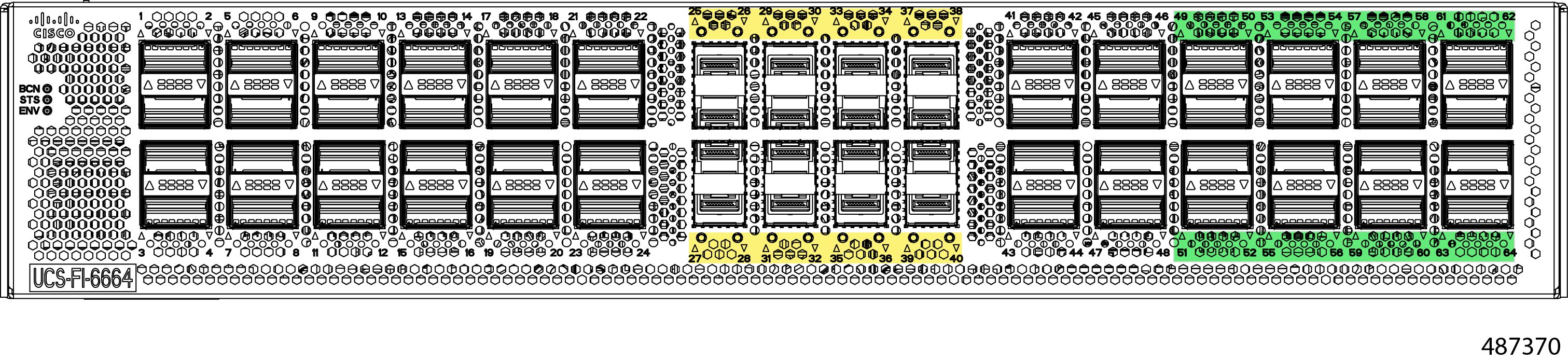
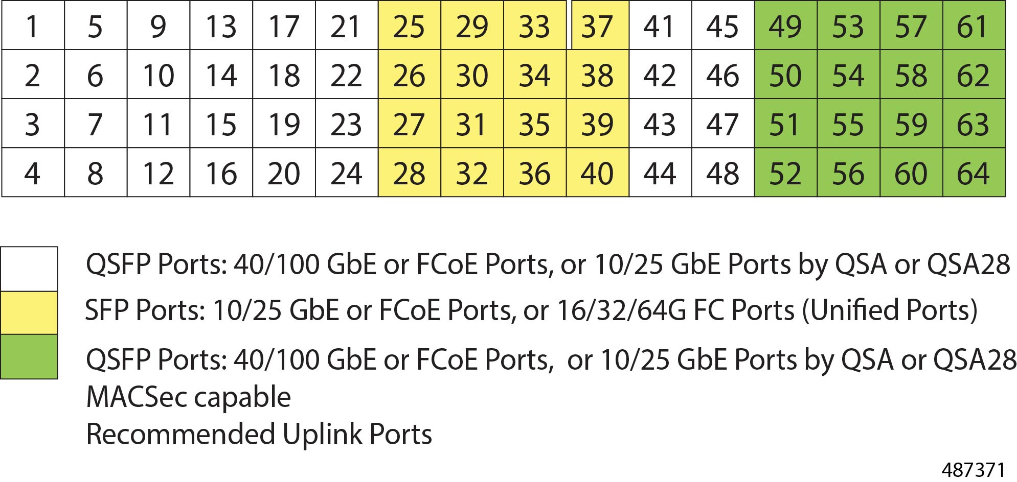
The Cisco UCS 6664 Fabric Interconnect (FI) is a 2-RU top-of-rack switch that mounts in a standard 19-inch rack such as the Cisco R Series rack. The 6664 is a 10/25/40/50/100 Gigabit Ethernet, FCoE and Fiber Channel switch offering up to 11.65 Tbps throughput and up to 64 ports. The switch has 16 unified ports (port numbers 25-40 marked with yellow silkscreen) that can support 10/25/50-Gbps SFP Ethernet ports or 16/32/64-Gbps Fibre Channel ports, 48 40/100-Gbps Ethernet QSFP ports (port numbers 1-24 and 41-64). All Ethernet ports are capable of supporting FCoE. MACsec-capable QSFP ports 49-64 are marked with green silkscreen.
The also has one network management port, one console port for setting the initial configuration, and one USB port for saving or loading configurations. It also includes L1/L2 ports for connecting two fabric interconnects for high availability.
The Cisco UCS 6664 Fabric Interconnect fabric interconnect contains its own environmentals, such as power supplies and fans, on the rear panel of the chassis.
-
Power supplies are redundant (1+1) that load share while both PSUs are operational, but a single PSU can power the entire fabric interconnect as needed, for example, during a PSU swap out.
-
Fans are also redundant (N+1) and load sharing, and they are color-coded to show intake airflow from the cold aisle to exhaust into the hot aisle in the data center (port-side exhaust air flow). Fans are grouped as two fans per fan module with four total modules per fabric interconnect for a total of eight fans per system.
The chassis also features the following, as shown in the following illustration.
-
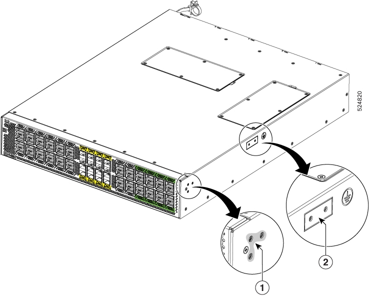
Areas on both side of the chassis for attaching mounting brackets. As rack mount kit is provided.
-
For electrical ground, the chassis contains a grounding pad as shown in the figure .
|
1 |
Screw holes for front mounting brackets (both left and right sides) |
2 |
Grounding pad |
Fabric Interconnect Front Panel
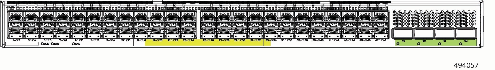
The fabric interconnect front panel contains the following fabric ports and system LEDs.
-
Fabric ports can be Gigabit Ethernet (GbE), Fibre Channel (FC), or Fibre Channel over Ethernet (FCoE). Typically, ports support only GigE or FCoE. However, some ports, called Unified Ports, can support all three connection types. For information about which ports support which connection types, and what speeds the ports support, see Ports and Port Numbering.
-
System LEDs provide visual indicators of the operational states of the systems. For more information, see Chassis LEDs.
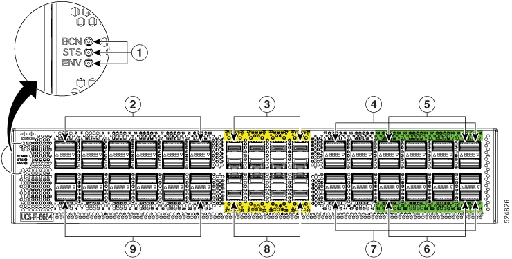
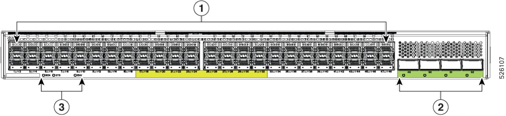
The following table shows the contents of the fabric interconnect front panel. Ports are arranged in vertical columns as two pairs of ports.
|
1 |
Beacon (BCN), Status (STS), and Environment (ENV) LEDs |
2 |
QSFP Ports 1, 2, 5, 6, 9,10, 13, 14, 17, 18, 21, and 22. Ports are arranged vertically in pairs and support QSA or QSA28 transceivers. |
|
3 |
SFP Ports 25, 26, 29, 30, 33, 34, 37, and 38 are Unified Ports as indicated by the yellow silk screening. |
4 |
QSFP Ports 41, 42, 45, 46, 49, 50, 53, 54, 57, 58, 61, and 62. |
|
5 |
MACsec-capable QSFP ports 49, 50, 53, 54, 57, 58, 61, and 62. |
6 |
MACsec-capable QSFP ports 51, 52, 55, 56, 59, 60, 63, and 64. |
|
7 |
QSFP Ports 43, 44,47, 48, 51, 52, 55, 56, 59, 60, 63, and 64. |
8 |
SFP Ports 27, 28, 31, 32, 35, 36, 39, and 40 are Unified Ports as indicated by the yellow silk screening. |
|
9 |
QSFP Ports 3, 4, 7, 8, 11,12, 15, 16, 19, 20, 23, and 24. Ports are arranged vertically in pairs and support QSA or QSA28 transceivers. |
Chassis LEDs
The BCN, STS, and ENV LEDs are located on the left side of the front of the fabric interconnect. The port LEDs appear as triangles pointing up or down to the nearest port.
|
LED |
Color |
Status |
|---|---|---|
|
BCN |
Flashing blue |
The operator has activated this LED to identify this fabric interconnect in the chassis. |
|
Off |
This fabric interconnect is not being identified. |
|
|
STS |
Green |
The fabric interconnect is operational. |
|
Flashing amber |
The fabric interconnect is booting up. |
|
|
Amber |
Temperature exceeds the minor alarm threshold. |
|
|
Red |
The fabric interconnect is not operational or temperature exceeds the major alarm threshold. |
|
|
Off |
The fabric interconnect is not receiving power. |
|
|
ENV |
Green |
Fans and power supply modules are operational. |
|
Amber |
At least one fan or power supply module is not operating. |
|
|
(port) |
Green |
Port admin state is 'Enabled', SFP is present and the interface is connected (that is, cabled, and the link is up). |
|
Amber |
Port admin state is 'Disabled, or the SFP is absent, or both. |
|
|
Off |
Port admin state is 'Enabled' and SFP is present, but interface is not connected. |
Uplink Module LEDs
There is a Status LED located below each uplink port.
|
LED |
Color |
Status |
|---|---|---|
|
QSFP Port State |
Green |
Port admin state is Enabled. The SFP is present, and the interface is connected (cabled and the link is up) |
|
Amber |
Port admin state is Disabled or the SFP is absent, or both |
|
|
Off |
Port admin state is Enabled, and the SFP is present, but interface is not connected |
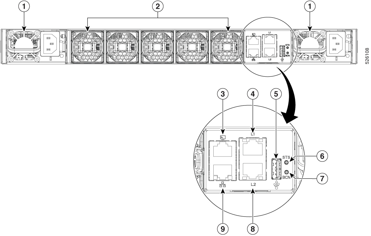
Fabric Interconnect Rear Panel
The fabric interconnect rear panel contains the management module, fans, and power supplies. 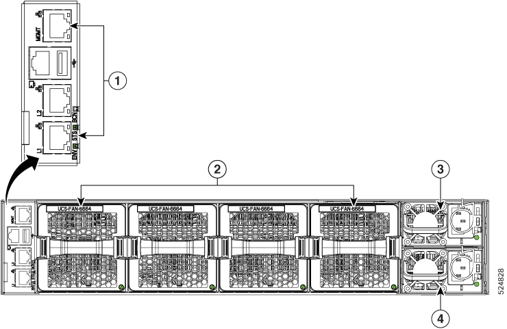
|
1 |
Management module ports |
2 |
Fan Modules, numbered one through four with fan 1 on the left and fan four on the right. |
|
3 |
Power Supply 1. |
4 |
Power Supply 2 |
Management Module
The management module enables connection to the fabric interconnect through any of the following:
-
One RJ-45 Ethernet MGMT port for management console connectivity, supporting 10/100/1000Mb speeds (labeled MGMT on the module)
-
Two L1/L2 Ethernet RJ-45 ports for high availability or cluster configurations, supporting 10/100/1000Mb speeds (labeled L1 and L2 on the module)
-
One RS-232 console port
-
One USB port, supporting USB v3.0 and v2.0 speeds
The management module also contains the following system health LEDs (chassis LEDs) that provide visual indicators of operational and performance status of the fabric interconnect:
-
ENV is the environmental LED, which indicates the status of cooling and power in the fabric interconnect.
-
STS is the Status LED, which indicates the boot-time or run-time operational state of the fabric interconnect.
-
BCN is the Beacon LED, which identifies a specific fabric interconnect in a rack or back of network equipment.
The same set of LED exists on the chassis front panel. For information about these LEDs, see Chassis LEDs.
Fan Modules
The fabric interconnect features four fan modules, numbered from left to right starting at fan 1. Each fabric interconnect fan module supports the following:
-
Port-side exhaust airflow only with blue coloring (UCS-FAN-6664).
-
Standard operation at the following fan speeds:
-
Typical/minimum: 45% of maximum RPMs.
-
Maximum: 80% of maximum RPMs.
-
 Note |
|
Each fan has a status LED that provides a visual indicator of operational and performance information. For information, see Fan Module LEDs.
Power Supplies
The fabric interconnect features two redundant (1+1) power supplies (PSUs). Power supplies are arranged vertically with power supply 1 on top. One PSU can power the fabric interconnect, but it is a best practice to only operate the fabric interconnect with one PSU for short periods of time, for example, while swapping out a fan.
The fabric interconnect supports 1400W port-side exhaust AC power supply modules with blue coloring (UCS-PSU-6600-AC).
Each power supply has a status LED that provides a visual indicator of operational and performance information. For information, see Power Supply LEDs.
Power Supply and Fan Considerations
The fabric interconnect supports fan and power supply modules with port-side exhaust airflow. Fans and PSUs with port-side exhaust are color coded blue.
The fan and power supply modules are field replaceable and you can replace one fan module or one power supply module during operations so long as the other modules are installed and operating. If you have only one power supply installed, you can install the replacement power supply in the open slot before removing the original power supply.
Note |
|
 Caution |
For port-side exhaust airflow (blue coloring for fan modules), you must locate the ports in the hot aisle. If you locate the air intake in a hot aisle, the fabric interconnect can overheat and shut down. |
Fan Module LEDs
The fan module status LED is located below the air holes on the front of the fan module. Every fan module has an LED.
| LED | Color | Status |
|---|---|---|
|
Status |
Green |
The fan module is operational. |
|
Red |
The fan module is not operational (fan is probably not functional). |
|
|
Off |
Fan module is not receiving power. |
Power Supply LEDs
The power supply LEDs are located on the right portion of the power supply. Combinations of states indicated by the OK and Fault LEDs signify the status for the module as shown in this table.
|
OK LED |
FAIL or FAIL/ID LED |
Status |
|---|---|---|
|
Green |
Off |
Power supply is on and outputting power to the fabric interconnect. |
|
Flashing green |
Off |
Power supply is connected to a power source but not outputting power to the fabric interconnect. The power supply may not be properly installed in the chassis. |
|
Off |
Off |
Either all the installed power supplies are not receiving power or an uninstalled power supply is not receiving power. |
|
Off |
Flashing amber |
Power supply is operating but a warning condition has occurred—possibly one of these conditions:
|
|
Off |
Flashing amber (10 seconds) then amber |
Power supply is installed without a connection to a power source. |
|
Off |
Amber |
Power supply failure—possibly one of these conditions:
|
Ports and Port Numbering
Ports
The Cisco UCS 6664 Fabric Interconnect has these ports:
-
Gigabit Ethernet (GbE) ports:
-
Ports 1 through 24 are QSFP ports that support Gigabit Ethernet links at the following speeds:
-
10 Gbps using QSA transceivers
-
25 Gbps using QSA28 transceivers
-
40Gbps and 100Gbps using an appropriate cable or transceiver
-
-
Ports 25 through 40 are unified ports that support Gigabit Ethernet or Fibre Channel through SFP port transceivers at the following link speeds:
-
Fibre Channel: 16Gbps, 32Gbps, or 64Gbps
-
Gigabit Ethernet: 10Gbps, 25Gbps, or 50 Gbps
Note
With version 6.0.2 and later, the Cisco UCS 6664 Fabric Interconnect supports 50 Gbps Gigabit Ethernet on unified ports.
-
-
Ports 41 through 64 are QSFP ports that support Ethernet at the following speeds:
-
10 Gbps using QSA transceivers
-
25 Gbps using QSA28 transceivers
-
40Gbps and 100Gbps using an appropriate cable or transceiver
-
-
Ports 49 through 64 are recommended as uplinks and support Media Access Control Security (MACsec) as defined by IEEE standard 802.1AE. MACsec is supported on Gigabit Ethernet links or uplinks, but not FCoE links or uplinks.
-
-
Fibre Channel Ports: Ports 25-40 support standard Fibre Channel links, as well as Gigabit Ethernet links through SFP port transceivers. These are the only ports on the Fabric Interconnect that support standard FC traffic.
-
Fibre Channel: 16Gbps, 32Gbps, or 64Gbps.
-
Gigabit Ethernet or Fibre Channel over Ethernet: 10Gbps or 25Gbps
-
-
All ports that support Gigabit Ethernet also support FibreChannel over Ethernet (FCoE) traffic.
To determine which transceivers, adapters, and cables are supported by this fabric interconnect, see the Cisco Transceiver Modules Compatibility Information document.
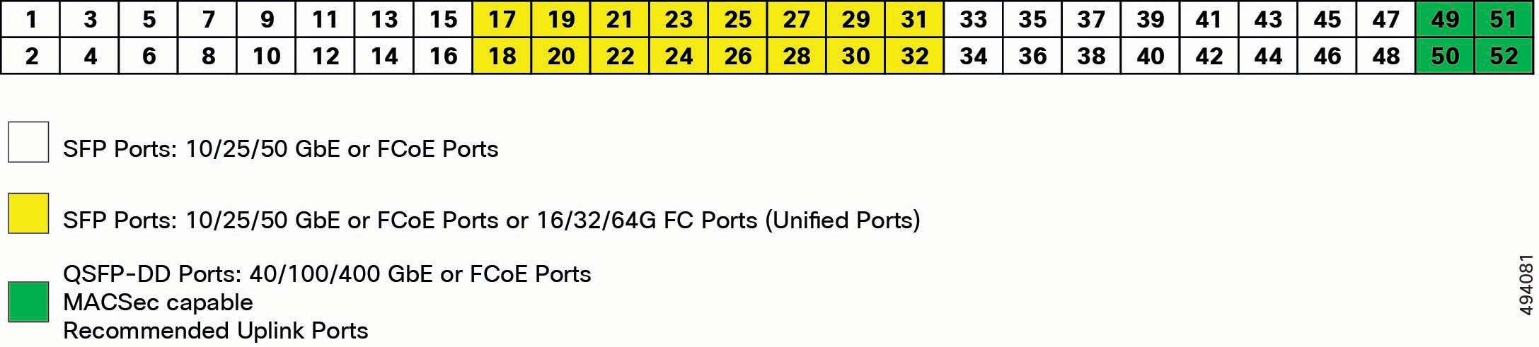
Port Numbering
Ports numbers are labeled on the chassis for easy reference. Different ports numbers support different connection types as indicated on the chassis by color coding. See the following illustration.
 Feedback